Note: Descriptions are shown in the official language in which they were submitted.
CA 02671866 2009-06-08
1
DESCRIPTION
*
Analysis Chip and Analysis Method
TECHNICAL FIELD
[0001]
The present invention relates to an analysis chip having a
substrate on which a substance capable of selectively binding
to a test substance, that is, a selective binding substance, is
immobiltireeda, and ria:::i:nc:niapl.ytical method for the test substance
using
BACKGROUND ART
[0002]
An analysis chip has a substrate on which a selective
binding substance such as a gene, protein, lipid, saccharide or
the like is immobilized, which selective binding substance on
the substrate is allowed to react with a test substance which
is usually in the form of a solution and, from the result of
the reaction, presence or absence, condition, or quantity of
the test substance is analyzed. Examples of this substrate
generally include those made of a glass, metal or resin.
[0003]
As one embodiment of an analysis chip, there is an
analysis chip called microarray whose substrate has molecules
such as DNA deposited thereon at high density for the purpose
of assaying expression of hundreds to tens of thousands of
numerous genes at the same time. By using microarrays,
systematic and exhaustive gene expression analyses can be
CA 02671866 2009-06-08
2
carried out on various disease animal models and cell
biological phenomena. In particular, functions of genes, that
is, proteins encoded by the genes can be clarified, and timing
of expression of the proteins and places where they act can be
identified. It is thought that searching of disease genes and
genes related to therapies, and finding of therapeutic methods
are possible by analyzing variation of gene expression of
organisms at the cell or tissue level by microarrays, and
constructing databases for gene expression profiles by
combining the resulting data with data on physiological, cell
biological and biochemical phenomena.
[0004]
At present, two basic methods, that is, the Gene Chip
method and the cDNA analysis chip method are used for
preparation of analysis chips.
[0005]
The Gene Chip method is a method developed by Affymetrix,
wherein oligoDNAs of about 25 mer are synthesized on a glass
plate by photolithography, which 25 mer oligoDNAs are designed
based on the base sequences from 16 to 20 regions per gene, and
the set of the perfectly matching 25 mers and a set of
oligomers having a mismatch of one base introduced
intentionally by changing the 13th base is used in combination
as probe DNAs. Since, in this method, the lengths of the probe
DNAs are constant and their sequences are known, GC content
which affects hybridization intensity can be made to be
constant, so that the above chip is considered to be an ideal
analysis chip for a quantitative analysis of expression. On
CA 02671866 2009-06-08
3
the other hand, the cDNA analysis chip method is a method
developed by Stanford University, wherein DNA is immobilized on
a glass plate by a method such as the spotting method or the
ink-jet method. When an analysis chip prepared by any of these
methods is used, a sample (gene) to be measured which was
preliminarily fluorescently labeled is allowed to bind to probe
DNAs on the analysis chip by hybridization, and its
fluorescence intensity is measured by a scanner to assay
expression of the gene.
[0006]
An example of analyses of analysis chip data is
hierarchical clustering. By this method, genes having similar
expression patterns are collected to prepare a phylogenetic
tree, and the expression levels of many genes are schematically
represented by different colors. Such clustering enables
identification of genes related to certain diseases.
[0007]
Analysis chips have been more and more used as methods to
test and analyze not only nucleic acids such as DNAs but also
proteins and saccharides. Especially, in chips for analysis of
proteins, proteins such as antibodies, antigens and enzyme
substrates are immobilized on the substrate.
[0008]
When using an analysis chip, it is important to apply a
prepared solution containing a test substance such that the
solution spreads evenly over the region on the analysis chip
where a selective binding substance is immobilized. As means
for achieving this, analysis chips having particles therein for
CA 02671866 2009-06-08
4
stirring the solution containing a test substance are known.
[0009]
Patent Literature 1 discloses an analysis chip wherein a
particle dispersion prepared by preliminarily adding particles
in a test substance DNA solution is applied to the analysis
chip, which chip is then covered by a cover glass and sealed by
a sealing agent, to create a void defined by the cover glass,
analysis chip substrate and sealing agent. This analysis chip
enables hybridization under stirring using the motion of the
particles, without evaporation of the test substance solution.
[0010]
Patent Literature 2 discloses an analysis chip wherein
irregularities are provided on the analysis chip substrate, and
a selective binding substance is immobilized on protruded
portions of the irregularities and particles for stirring are
movably contained in recessed portions thereof, to enable
stirring of the reaction solution. Since, in this analysis
chip, the particles are kept away from upper surfaces of the
protruded portions, stirring with the particles may be carried
out without damaging the selective binding substance.
[0011]
However, in analysis chips wherein stirring is carried out
using particles as above, when the solution containing the test
substance is applied thereto, bubbles may remain on the surface
inside the analysis chip substrate or on the surfaces of the
particles, or may be generated in the reaction solution. There
has been a problem that the generated bubbles inhibit the
reaction between the selective binding substance and the test
ak 02671866 2009-06-08
substance in the areas where the bubbles stay. Furthermore,
there has been a problem that unevenness of the reaction
between the areas where the bubbles stay and the other areas
causes deviation of detection sensitivity or lowering of
5 detection sensitivity.
[0012]
Furthermore, when the particles for stirring are contained
or injected in the void between the analysis chip substrate and
the cover, operation of injection of the particles into the
void may be difficult or injection of a sufficient amount of
the particles may not be achieved due to electrostatic
generation or the like. Furthermore, the injected particles
may aggregate and become immobile and, in cases where the test
substance solution is injected into the void surrounded by the
cover and the substrate in such a condition, the solution does
not permeate the areas where the particles aggregate, resulting
in entrapping of bubbles, which causes unevenness of the
reaction.
Patent Literature 1 JP 3557419 B
Patent Literature 2 WO 2005/090997
DISCLOSURE OF THE INVENTION
PROBLEMS TO BE SOLVED BY THE INVENTION
[0013]
The present invention is directed to resolution of the
above problems and provides an analysis chip which suppresses
generation of bubbles which inhibit the selective reaction
CA 02671866 2013-08-07
.76199-290
6
between a test substance and an immobilized selective binding
substance, thereby reducing deviation of detection sensitivity
and lowering of detection sensitivity caused by unevenness of
the reaction. The present invention also provides an analysis
chip which prevents aggregation of particle S for stirring and
simplifies injection of the particles for stirring into the
void between the analysis chip substrate and its cover.
MEANS FOR SOLVING THE PROBLEMS
[0014]
The present inventors intensively studied to discover that
the above problems may be solved by coating the surfaces of the
particles for stirring with a surfactant, thereby completing
the present invention.
[0015]
That is, the present invention is an analysis chip
comprising: a substrate having a surface on which a selective
binding substance(s) is(are) immobilized; a cover member
adhered to the substrate; a void between said substrate and
said cover member; and particles for stirring a test substance
solution movably contained or injected in the void; the
surfaces of the particles being coated with a surfactant(s).
(0016]
In one preferred embodiment of the analysis chip of the
present invention, the surfactant coated on the surfaces of the
particles is an anionic surfactant or a nonionic surfactant.
[0017]
Further, one preferred embodiment of the analysis chip of
CA 02671866 2009-06-08
7
, the present invention is a substrate comprising an irregular
region composed of recessed portions and protruded portions,
wherein the selective binding substance(s) is(are) immobilized
on upper surfaces of the protruded portions.
[0018]
Further, in one preferred embodiment of the analysis chip
of the present invention, the material constituting the
particles coated with the surfactant(s) comprises a ceramic.
[0019]
Further, in one preferred embodiment of the analysis chip
of the present invention, one or more penetrating holes
communicating with the void are formed in the cover member.
[0020]
Further, in one preferred embodiment of the analysis chip
of the present invention, the shortest distance between the
surface of the substrate, on which the selective binding
substance(s) is(are) immobilized, and the cover member is
smaller than the diameter of the particles.
[0021]
Further, in one preferred embodiment of the analysis chip
of the present invention, the selective binding substance is a
DNA, RNA, protein, peptide, saccharide, sugar chain or lipid.
[0022]
Further, the present invention is a method for analyzing a
test substance, the method comprising the steps of:
bringing the analysis chip of the present invention into
contact with a solution containing a test substance, thereby
selectively binding the test substance to the selective binding
CA 02671866 2009-06-08
8
substance immobilized on the surface of the substrate; and
measuring the amount of the test substance bound to the
analysis chip through the selective binding substance.
[0023]
One preferred embodiment of the method of the present
invention for analyzing a test substance is a method wherein
the solution containing the test substance is subjected to a
degassing treatment before bringing the solution containing the
test substance into contact with the analysis chip
EFFECT OF THE INVENTION
[0024]
According to the analysis chip of the present invention,
retention and generation of bubbles in the reaction solution in
the analysis chip may be suppressed. As a result, deviation of
detection sensitivity and lowering of detection sensitivity due
to unevenness of reaction caused by inhibition of the reaction
between the selective binding substance and the test substance
by the bubbles may be suppressed, thereby allowing detection of
the test substance with higher sensitivity.
[0025]
Further, according to the analysis chip of the present
invention, aggregation of particles may be prevented, and
injection of the particles into the void between the analysis
chip substrate and its cover member may be carried out easily
and smoothly.
BRIEF DESCRIPTION OF THE DRAWINGS
CA 02671866 2009-06-08
9
, [0026]
Fig. 1 is a cross-sectional view schematically showing an
example of the substrate constituting the analysis chip of the
present invention, on which substrate a selective binding
substance is immobilized.
Fig. 2 is a cross-sectional view schematically showing an
example of generation of a bubble on the surface of the
substrate by usage of the substrate in Fig. 1.
Fig. 3 is a perspective view schematically showing an
example of the substrate constituting the analysis chip of the
present invention, on which substrate a selective binding
substance is immobilized.
Fig. 4 is a cross-sectional view schematically showing an
example of the substrate in Fig. 3 constituting the analysis
chip of the present invention, on which substrate a selective
binding substance is immobilized.
Fig. 5 is a longitudinal sectional view schematically
showing an example of a jig and a scanner which read results of
a reaction using the substrate constituting the analysis chip
of the present invention, on which substrate a selective
binding substance is immobilized.
Fig. 6 is a perspective view showing an example of
penetrating holes and liquid level-halting chambers.
Fig. 7 is a cross-sectional view schematically showing an
example of the analysis chip of the present invention.
Fig. 8 is a cross-sectional view schematically showing an
example of the analysis chip of the present invention.
Fig. 9 is a cross-sectional view schematically showing an
CA 02671866 2009-06-08
example of the analysis chip of the present invention.
Fig. 10 is a perspective view schematically showing an
example of the analysis chip of the present invention having a
partition structure.
5 Fig. 11 is a longitudinal sectional view schematically
showing another example of the analysis chip of the present
invention having a partition structure.
Fig. 12 is a longitudinal sectional view schematically
showing an example of preferred relationships among the
10 irregular region, cover member and particles
DESCRIPTION OF SYMBOLS
[0027]
1 Substrate
2 Particles
3A Protruded portion of cover member
3, 3B Cover member
10 Recessed portion
11 Protruded portion
12 Region on which selective binding substance is
immobilized (irregular region)
13 Flat area
14 Protruded portion of substrate
26 Example of generated bubble
30, 30C Adhesive member
30A, 30B Adhesive member for partition structure
31 Void or space
32 Penetrating hole
CA 02671866 2009-06-08
11
33 Liquid level-halting chamber
34 Sealing member (tape)
35 Void between substrate and cover member
40 Spring for urging microarray to jig
41 Jig
42 Abutting surface of jig
43 Objective lens
44 Laser excitation light
45 Selective binding substance immobilized on substrate
Li Pitch between protruded portions
BEST MODE FOR CARRYING OUT THE INVENTION
[0028]
The analysis chip of the present invention is
characterized in that it has a void between a substrate having
a surface on which a selective binding substance is immobilized
and a cover member adhered to the substrate, in which void
particles are movably contained or injected, and that the
surfaces of the particles are coated with a surfactant.
Coating with a surfactant means that a surfactant is applied or
adhered to the surface of the particle or that the surface of
the particle is covered with the surfactant, partially or
entirely. This coating may be carried out for example by a
method described later.
[0029]
Fig. 1 shows an example of the analysis chip of the
present invention containing particles. In the example shown
in Fig. 1, the surface of the substrate 1 comprises irregular
CA 02671866 2009-06-08
12
regions constituted by recessed portions 10 and protruded
portions 11. The particles 2 are contained in the recessed
portions 10, and the selective binding substance 45 (nucleic
acid, for example) is immobilized on the upper surfaces of the
protruded portions 11.
[0030]
When adding a solution containing a test substance to the
analysis chip in order to allow the test substance to react
with the selective binding substance 45 (nucleic acid, for
10- example) immobilized on this substrate 1, microbubbles adhered
to the surfaces of the particles 2 are liberated into the
liquid to form a bubble 26 which covers the protruded portions
as shown in Fig. 2, so that the selective binding substance on
the surfaces of the covered protruded portions cannot react
with the test substance. In the analysis chip of the present
invention, by virtue of the fact that the surfaces of the
particles 2 are coated with a surfactant, bubbles do not adhere
to, or are less likely to adhere to, the surfaces of the
particles, thereby enabling suppression of generation of the
bubbles. By this, the entire selective binding substances 45
on the surface of the substrate 1 can react with the test
substance, and the reliability and reproducibility of obtained
data may be increased.
[0031]
Examples of the method for coating the surfaces of the
particles with a surfactant include known methods such as:
methods wherein the particles are immersed in a solution
containing the surfactant and dried after removal therefrom;
CA 02671866 2009-06-08
13
=
methods wherein a solution containing the surfactant is sprayed
on the surfaces of the particles, which are then dried; methods
wherein the particles are brought into contact with a substance
containing a solution of the surfactant; and methods wherein
the particles are brought into contact with a liquid, and the
surfactant in the form of power is sprinkled thereon. After
coating the surfaces of the particles with the surfactant(s) by
spraying, adherence or the like using these methods, the
particles may be used also after washing away an excess amount
of the surfactant with water or an organic solvent. The
concentration of the solution containing the surfactant used in
these methods is preferably 0.01% to 10%, more preferably 0.05%
to 2%.
[0032]
Examples of the surfactant used for the surface treatment
of the particles include anionic surfactants, cationic
surfactants, amphoteric surfactants and nonionic surfactants
and, among these, anionic surfactants and nonionic surfactants
are preferably used.
[0033]
Examples of the anionic surfactants include sodium dodecyl
sulfate (SDS), sodium cholate, sodium deoxycholate, sodium
lauryl sarcosinate, polyoxyethylene alkyl ether phosphate,
polyoxyethylene alkyl phenyl ether phosphate, triethanolamine
lauryl sulfate and sodium lauroyl sarcosinate.
[0034]
Examples of the cationic surfactants include
cetyltrimethylammonium bromide (CTAB), lanolin fatty acid
CA 02671866 2013-08-07
. 76199-290,
14
=
aminopropylethyldimethylammonium ethyl sulfate,
alkyltrimethylammonium chloride, dialkyldimethylammonium
chloride, distearyldimethylammonium chloride,
- distearyldimethylbenzylammonium chloride and
stearyltrimethylammonium chloride.
[0035] =
Examples of the amphoteric surfactants include 3-[(3-.
cholamidopropyl)dimethylammonio]-2-hydroxypropanesulfonate
(CHAPS0), 3-[(3-
cholamidopropyl)dimethylamMonio]propanesulfonate (CHAPS), and
n-dodecyl-N,N-dimethy1-3-ammonio-l-propanesulfonate
(ZWITTERGENT 3-12 Detergent).
[0036]
Examples of the nonionic surfactants include
. dimethyldecylphosphine oxide (APO7-10), dodecyldimethylphosphine
TM -
oxide (AP012), polyqxyethylene lauryl ether (BRIJ-35),
polyoxyethylene (20) cetyl ether (BRIJ-58), -polyoxyethylene
(80) sorbitan monooleate ester (polysorbate 80, TweenTm80),.
polyoxyethylene (20) sorbitan monolaurate ester (polysorbate 20,
Tweer720), polyethylene glycol p-(l,l,3,3-
TM
tetramethylbutyl)phenyl ether (TRITON X-100), TRITON%-114,'n-
decanoyl-N-methyl-D-glucamine (MEGA1410), n-nonanoyl-N-methyl-D-
TM
glucamine (MEGA-9), n-octanoyl-N-methyl-D-glucamine (MEGA-8),
=
nonylphenyl-polyethylene glycol (NP-40), polyoxyethylene
polyoxypropylene glycol, ethylene glycol monostearate, sorbitan
monostearate, propylene glycol monostearate; polyoxyethylene.
sorbitan monostearate, polyoxyethylene (160) polyoxyprppylene
TN,
(30) glycol (Pluronic F68), and polyoxyethylene (196)
ak 02671866 2009-06-08
s polyoxypropylene (67) glycol (Pluronic F127).
[0037]
Among these, because of their strong surface-activating
effect, sodium dodecyl sulfate (SDS) and sodium deoxycholate
5 are especially preferably used as the anionic surfactant, and
Pluronic F68 and Pluronic F127 are especially preferably used
as the nonionic surfactant.
[0038]
The shape of the particle is not restricted as long as it
10 may stir the test substance solution, and the particle may be
in an arbitrary shape, for example, a polygon or micro-rod
(fine rod) such as a cylinder or prism, in addition to sphere.
[0039]
The size of the particle is also not restricted, and the
15 diameter of the particle is preferably less than the shortest
distance between the surface of the substrate on which the
selective binding substance is immobilized and the cover member.
For example, in cases where the particle is spherical, its size
may be in the range of 0.1 pm to 300 pm. In cases where the
particle is cylindrical, the diameter of its bottom surface is
regarded as the diameter of the particle, and the diameter of
the bottom surface is preferably less than the shortest
distance between the surface of the substrate on which the
selective binding substance is immobilized and the cover member.
For example, in cases where the particle is cylindrical, its
length may be in the range of 50 pm to 5000 pm, and the
diameter of its bottom surface may be in the range of 10 pm to
300 pm.
ak 02671866 2009-06-08
16
, [0040]
The material constituting the particle is also not
restricted, and examples thereof include glasses; ceramics
(such as yttrium partially-stabilized zirconia); metals and
metal oxides such as gold, platinum, stainless, iron, aluminum
oxide (alumina) and titanium oxide (titania); and plastics such
as nylons and polystyrenes.
[0041]
The surface of the particle which is coated with the
surfactant preferably has an appropriate roughness. That is,
the centerline average roughness (Ra value) is preferably not
less than 40 nm and not more than 300 nm. By using the
particle having the surface roughness in this range, the
surface area of the bead is increased, so that the surface of
the particle may be coated with more surfactant. In cases
where the particle is made of a ceramic, the Ra value is
preferably not less than 40 nm and not more than 200 nm in
consideration of the strength of the material.
[0042]
The substrate constituting the analysis chip of the
present invention preferably has an irregular region composed
of recessed portions and protruded portions, on which protruded
portions the selective binding substance is immobilized. Due
to such a structure, a nonspecifically-adsorbed test substance
is not detected and the noise is reduced in the detection
process, thereby results may be obtained with better S/N. A
specific reason for the reduction of the noise is as follows.
That is, when the substrate wherein the selective binding
ak. 02671866 2009-06-08
17
, substance is immobilized on the upper surfaces of the protruded
portions is scanned using an apparatus called a scanner, the
upper surfaces of the protruded portions are focused by the
laser light, thereby the laser light becomes dim at the
recessed portions, so that undesirable fluorescence (noise)
from the test substance nonspecifically adsorbed to the
recessed portions is less likely to be detected.
[0043]
The heights of the protruded portions in the irregular
region are preferably about the same with each other in terms
of the heights of the upper surfaces of the protruded portions.
Here, the heights are regarded as being about the same in cases
where the selective binding substance is immobilized on the
surfaces of the protruded portions whose heights vary to a
certain extent, which substance is then reacted with the
fluorescence-labeled test substance, and scanning is carried
out by the scanner, resulting in observation of signals wherein
variation of the levels of their intensity does not cause a
problem. Specifically, the heights are about the same in cases
where the differences among the heights are not more than 50 pm.
The differences among the heights are more preferably not more
than 30 pm and, still more preferably, the heights are the same.
As used herein, "the same height" includes the error due to the
variation produced during the process of production or the like.
In cases where the difference between the height of the upper
surface of the highest protruded portion and the height of the
upper surface of the lowest protruded portion is larger than 50
pm, the laser light becomes dim at the upper surfaces of the
CA 02671866 2009-06-08
18
protruded portions with different heights, and the intensity of
the signal from the test substance reacted with the selective
binding substance immobilized on these upper surfaces of the
protruded portion may be decreased, which is not preferred.
[0044]
In the substrate constituting the analysis chip of the
present invention, the 'region on which the selective binding
substance (nucleic acid, for example) is immobilized is not
restricted as long as it is on the surface of the substrate and
roughening as described above has not been performed thereto
and, in particular, it is preferably the upper surface (upper
end surface) of the protruded portion of the irregular region
described above. Immobilization of the selective binding
substance may be carried out in advance; or only the substrate
is prepared without immobilization and, when the test substance
is analyzed, the selective binding substance corresponding to
the desired test substance may be appropriately selected and
immobilized
[0045]
As the selective binding substance (nucleic acid, for
example) which can be immobilized on the upper surfaces of the
protruded portions, one necessary for obtaining data may be
appropriately selected, but it may also be a mere dummy
selective binding substance. It is not necessary to bind the
selective binding substance to all the upper surface of the
protruded portions, and there may be upper surfaces on which
nothing is immobilized.
[0046]
CA 02671866 2009-06-08
19
In the substrate constituting the analysis chip of the
present invention, when the selective binding substance(s)
is(are) immobilized on the upper surfaces of the protruded
portions, the areas of the upper surfaces of the protruded
portions are preferably about the same. The upper surfaces of
the protruded portions having about the same areas are
advantageous for a later analysis since the areas of the
regions on which many types of the selective binding substances
are immobilized can be made to be the same. Here, the upper
surfaces are regarded as having about the same areas in cases
where the value obtained by dividing the largest upper surface
area among those of the protruded portions by the smallest
upper surface area is not more than 1.2.
[0047]
The area of the upper surface of the protruded portion on
which the selective binding substance is immobilized is not
restricted and preferably not less than 10 pm2 and not more
than 1 mm.2, more preferably not less than 300 pm2 and not more
than 0.8 mm2 from the view point of reducing the amount of the
selective binding substance and ease of handling.
[0048]
In the substrate constituting the analysis chip of the
present invention, the surface of the substrate, which surface
has the region on which the selective binding substance(s)
is(are) immobilized, is preferably surrounded by a flat area
having about the same height with the upper end of the
protruded portion of the irregular region. Due to such a
structure, a solution containing a test substance may be easily
CA 02671866 2009-06-08
, applied to the irregular region, and the particles for stirring
may be retrained in the recessed portions without being brought
into contact with the selective binding substance(s).
[0049]
5 The height of the upper surface of the protruded portion
in the irregular region and the height of the flat area are
preferably about the same. That is, the difference between the
height of the flat area and the height of the upper surfaces of
the protruded portions is preferably not more than 50 pm. In
10 cases where the difference between the height of the upper
surface of the protruded portion and the height of the flat
area is larger than 50 pm, the detectable fluorescence
intensity may be lowered, which is not preferred. The
difference between the height of the flat area and the height
15 of the upper surface of the protruded portion is more
preferably not more than 30 pm and, most preferably, the flat
area and the protruded portion have the same height.
[0050]
The height of the protruded portion in the irregular
20 region of the substrate preferably used in the analysis chip of
the present invention, that is, the difference between the
height of the upper surface of the protruded portion and the
height of the bottom surface of the recessed portion is
preferably not less than 10 pm and not more than 500 pm, more
preferably not less than 50 pm and not more than 300 pm. In
cases where the height of the protruded portion is less than 10
pm, the test substance nonspecifically adsorbed to a region
other than the spots may be detected, which results in a poor
CA 02671866 2009-06-08
21
,S/I\l'and is not preferred. In cases where the height of the
protruded portion is more than 500 pm, there may be a problem
in, for example, that the protruded portion is prone to be
broken and damaged, which is not preferred.
[0051]
Specific examples of the substrate constituting the
analysis chip of the present invention are exemplified in Fig.
3 and Fig. 4.
[0052]
In the examples shown in Fig. 3 and Fig. 4, the surface of
the substrate 1 comprises an irregular region 12 comprising
multiple protruded potions 11, which irregular region 12 is
surrounded by a flat area 13. On the upper surfaces of the
protruded portions 11, selective binding substance(s) (nucleic
acid, for example) is (are) immobilized. Usage of this flat
area enables easy focusing of the measurement light such as an
, excitation light of a scanner on the upper surface of the
protruded portion. More particularly, when the focusing is
carried out for radiation of the measurement light such as a
laser to the surface of the substrate, as shown in Fig. 5, the
substrate 1 is often urged by a spring 40 to a jig 41, and the
focus is adjusted in advance by the lens 43 or the like such
that the laser light 44 focuses on the height of an abutting
surface 42 of the jig. By abutting the flat area of the
substrate of the analysis chip of the present invention to the
surface 42 of the jig, the measurement light (laser light of
the scanner) can be easily focused on the upper surface of the
protruded portion of the substrate. In the example shown in
CA 02671866 2009-06-08
22
, Fig. 5, the substrate 1 is fixed such that the surface on which
the selective binding substance(s) is(are) immobilized faces
downward.
[0053]
The material which constitutes the substrate of the
analysis chip of the present invention is not restricted, and
examples thereof include glasses, ceramics, silicone resins,
polyethylene terephthalate, cellulose acetate, polycarbonate,
polystyrene, polymethyl methacrylate (PMMA), and silicone
rubbers such as polydimethylsiloxane (PDMS) elastomers. Among
these, polymethyl methacrylate, polystyrene,
polydimethylsiloxane (PDMS) elastomers, glasses or silicone
resins may be preferably used.
[0054]
At least a part of the substrate of the analysis chip of
the present invention is preferably black. This may reduce
autofluorescence from the substrate. The part(s) made to be
black may be the main body of the substrate having the
irregular region; the side surfaces of the protruded portions;
a hydrophobic material or insulating layer provided in the
recessed portion; or all of these.
[0055]
Here, the substrate is regarded as being black in cases
where the spectral reflectance of the black portion of the
substrate does not show a specific spectral pattern (such as
specific peaks) and is uniformly low and the spectral
transmittance of the black portion of the substrate also does
not show a specific spectral pattern (such as specific peaks)
CA 02671866 2013-08-07
. 76199-290
23
and is uniformly low, within the visible wavelength region (400
nm to 800 nm).
[0056]
With regard to the values of the spectral reflectance and
the spectral transmittance, the spectral reflectance within the
visible wavelength region (400 nm to 800 nm) is preferably not
more than 7%, apd the spectral transmittance within the same
wavelength region is preferably not more than 2%. As used
herein, the spectral reflectance means a spectral reflectance
measured with specular reflection from the substrate using an
illumination/light-receiving optical system satisfying the
condition C of Japanese Industrial Standards Z 8722.
[0057]
The black color of the substrate may be achieved by
incorporating a black substance in the substrate of the
analysis chip of the present invention. This black substance
is not restricted as long as it does not, or is less likely to,
reflect light, pr it does not, or is less likely to, allow
transmission of light, and preferred examples thereof include
black substances such as carbon black; graphite; titan black;
aniline black; oxides of Ru, Mn, Ni, Cr, Fe, Co or Cu; and
.carbides of Si, Ti, Ta, Zr or Cr.
[0058]
These black substances may be incorporated solely or as a
mixture of two or more kinds. For example, in the cases of a
polymer such as polyethylene terephthalate or a silicone resin,
_carbon black, graphite, titan black or aniline black among the
above black substances may be preferably incorporated, and
CA 02671866 2009-06-08
24
carfoon black may be especially preferably used. In the cases
of an inorganic material such as a glass or ceramic, a metal
oxide of Ru, Mn, Ni, Cr, Fe, Co, Cu or the like or a carbide of
Si, Ti, Ta, Zr or Cr may be preferably incorporated.
[0059]
The substrate constituting the analysis chip of the
present invention may be produced by various methods. For
example, in cases where the material is a polymer or the like,
the substrate may be molded by a method such as injection
molding, hot embossing or a method wherein polymerization is
carried out in a mold. In cases where the material is an
inorganic material such as a glass or ceramic, the substrate
may be molded by sand blasting, and in cases where the material
is a silicone resin, it may be molded by a known semiconductor
process or the like.
[0060]
The molded substrate may be subjected to various surface
treatments prior to immobilization of the selective binding
substance(s) on its surface. Specific examples of such surface
treatments include the one described in JP 2004-264289 A.
[0061]
The analysis chip of the present invention may be used as
an analysis chip for analyzing a test substance (sample).
[0062]
In the present invention, the analysis chip means a chip
used for assaying presence or absence of the test substance,
the quantity of the test substance, or properties of the test
substance, by applying a solution containing the test substance
CA 02671866 2009-06-08
, to the chip. Specifically, examples of the analysis chip
include biochips wherein a selective binding substance(s)
immobilized on the surface of its substrate is allowed to react
with a test substance in order to assay the quantity of the
5 test substance or presence or absence of the test substance.
More specifically, examples of the analysis chip include DNA
chips wherein a nucleic acid is immobilized on the surface of
its substrate, protein chips wherein a protein represented by
an antibody is immobilized on the surface of its substrate,
10 sugar chain chips wherein a sugar chain is immobilized on the
surface of its substrate, cell chips wherein a cell is
immobilized on the surface of its substrate.
[0063]
In the present invention, the selective binding substance
15 means various materials capable of binding selectively to a
test substance directly or indirectly. Representative examples
of the selective binding substances capable of binding to the
surface of the substrate include nucleic acids, proteins,
peptides, saccharides and lipids.
20 [0064]
The nucleic acid may be a DNA or RNA, and may also be a
PNA. Since a single-stranded nucleic acid having a particular
base sequence selectively hybridizes with a single-stranded
nucleic acid having a base sequence complementary to the base
25 sequence of the nucleic acid or a part thereof, the single-
stranded nucleic acid is a selective binding substance in the
present invention.
[0065]
CA 02671866 2009-06-08
26
The nucleic acid may be one derived from a natural product
such as a live cell or may be one synthesized by a nucleic acid
synthesizer. Preparation of DNA or RNA from live cells may be
carried out by a known method, for example, for extraction of
DNA, the method by Blin et al. (Blin et al., Nucleic Acids Res.
3: 2303 (1976)) or the like, and for extraction of RNA, the
method by Favaloro et al. (Favaloro et al., Methods Enzymo1.65:
718 (1980)) or the like. Examples of the nucleic acid which
may be immobilized further include linear or circular plasmid
DNAs and chromosomal DNAs, DNA fragments produced by digestion
of these DNAs with a restriction enzyme or by chemical cleavage
thereof, DNAs synthesized in vitro with an enzyme or the like,
or chemically synthesized oligonucleotides.
[0066]
Examples of the protein include antibodies and antigen-
binding fragments of antibodies such as Fab fragment and
F(ab')2 fragment, and various antigens. Since an antibody or
an antigen-binding fragment selectively binds to the
corresponding antigen, and since an antigen selectively binds
to the corresponding antibody, they are "selective binding
substances".
[0067]
Examples of the saccharide include various monosaccharides
and sugar chains such as oligosaccharides and polysaccharides.
[0068]
Examples of the lipid may include simple lipids and
complex lipids.
[0069]
CA 02671866 2009-06-08
27
Antigenic substances other than the above nucleic acids,
proteins, saccharides and lipids may also be immobilized. Cells
may also be immobilized on the surface of the substrate as the
selective binding substance.
[0070]
Among these selective binding substances, those especially
preferred are DNAs, RNAs, proteins, peptides, saccharides,
sugar chains and lipids.
[0071]
The analysis chip of the present invention further
comprises a cover member covering the surface of the substrate,
which cover member is adhered to the substrate. By comprising
the cover member, the solution containing the test substance
may be easily kept sealed and, as a result, the reaction
between the test substance and the selective binding
substance(s) immobilized in the region (12 in Fig. 3 or Fig. 4)
of the substrate may be stably carried out. The particles may
be preliminarily injected (contained) in the analysis chip of
the present invention so that the test substance solution may
be easily applied. There is also an advantage that the
background noise does not increase since the tape and sealing
agent do not contact the test substance solution during the
operation of closing the penetrating hole after applying the
test substance solution.
[0072]
Fig. 6 is a perspective view showing an example of
schematic embodiments of the analysis chip of the present
invention having, in addition to the substrate, a cover member,
CA 02671866 2009-06-08
28
, adhesive member, penetrating holes and liquid level-halting
chambers, and Fig. 7 is a cross-sectional view taken along the
plane indicated by the arrow Al in Fig. 6. In the example
shown in Fig. 7, the substrate 1 is covered with a cover member
3 via the adhesive member 30, to form a void 31 comprising the
region 12 where the selective binding substance(s) is(are)
immobilized. The void 31 is a closed space which does not
communicate with the outside except that it communicates with
the outside via a plurality of penetrating holes.
[0073]
The cover member may be adhered such that it covers at
least a part of a side of the surface of the substrate and
forms a void between the substrate and the cover member. The
substrate preferably has a selective binding substance(s)
immobilized on a region located in the void, which is the
surface of the substrate. That is, the cover member is
preferably adhered to the substrate such that the region
wherein the selective binding substance(s) is(are) immobilized
exists in the void. The cover member may be adhered in any
manner as long as the void is formed, and is preferably adhered
via an adhesive member such as a double-stick tape or resin
composition.
[0074]
The cover member may comprise one or more penetrating
holes communicating with the void, and preferably comprise 2 or
more penetrating holes. More specifically, one void preferably
has 2 or more penetrating holes, and it especially preferably
has 3 to 6 penetrating holes since filling of the solution
CA 02671866 2009-06-08
29
, containing the test substance is simple. As described later,
in cases where the void is partitioned into 2 or more spaces
which do not communicate with each other, each space preferably
has 2 or more, more preferably 3 to 6 penetrating holes. In
cases where the cover member has 2 or more penetrating holes,
their hole sizes may be the same or different, and in cases
where one of the 2 or more penetrating holes is used as an
inlet for application of the test substance solution while the
other(s) is/are made to function as an air outlet(s), the hole
size of the inlet is preferably wide enough to allow
application of the solution while the hole size(s) of the other
penetrating hole(s) is/are narrower from the view points of
simplicity of application of the solution and retention of
sealing. Specifically, the diameter of the penetrating hole of
the inlet for application is preferably within the range of
0.01 mm to 2.0 mm as described above, and the diameter(s) of
the other penetrating hole(s) is/are preferably within the
range of 0.01 mm to 1.0 mm.
[0075]
At least one of the penetrating holes 32 may have a
different diameter and comprise in its top end a portion with a
wider diameter, that is, the liquid level-halting chamber 33.
By having the liquid level-halting chamber, rising of the
liquid level of the test substance solution applied from the
penetrating hole 32 and filled in the void 31 may be suppressed,
so that sealing of the penetrating hole with the sealing member
34 (Fig. 12) can be simply and securely carried out and inflow
of the air into the test substance solution and outflow of the
CA 02671866 2009-06-08
test substance solution may be prevented, which are preferred.
The shape of the liquid level-halting chamber is not restricted,
and the chamber may be in a cylindrical, prismatic, conical,
pyramidal or hemispherical shape, or in a shape similar thereto.
5 Among these, the cylindrical shape is especially preferred from
the view points of simplicity of the production, efficiency of
suppressing of the increase of the liquid level of the test
substance solution, and the like.
[0076]
10 The size of the penetrating hole is not restricted, and in
the case of the combination of a cylindrical penetrating hole
32 and a liquid level-halting chamber 33, the hole size
(diameter) of the penetrating hole 32 is preferably 0.01 mm to
2.0 mm, more preferably 0.3 mm to 1.0 mm. With a hole size of
15 not less than 0.01 mm, the test substance solution can be
easily applied. On the other hand, by making the diameter of
the penetrating hole 32 not more than 1.5 mm, evaporation of
the test substance solution after application but before
sealing and the like may be effectively suppressed. The hole
20 size (diameter) of the liquid level-halting chamber 33 is
preferably not less than 1.0 mm. By making the hole size of
the liquid level-halting chamber not less than 1.0 mm, a
sufficient difference in size relative to the penetrating hole
32 can be obtained, so that a sufficient liquid level-halting
25 effect can be obtained, which is preferred. The upper limit of
the diameter of the liquid level-halting chamber is not
restricted, and it may be not more than 10 mm. The depth of
the liquid level-halting chamber is not restricted, and it may
CA 02671866 2009-06-08
31
,be within the range of 0.1 mm to 5 mm.
[0077]
Such a cover member is preferably movably adhered to the
above described substrate. In cases where the analysis chip of
the present invention is used as a DNA chip, it is usually
necessary to read the DNA chip using a special scanner, but the
chip is difficult to be placed in the special scanner with a
cover member adhered thereto, and even when the substrate could
be placed in the scanner, the cover member and the optical
system component may be made to contact with each other by
carrying out a scanning operation, which may result in a
trouble. Moreover, even when reading is possible through the
cover member, read values may not be accurate. Therefore, the
cover member is preferably removable so that the cover member
may be removed in the reading step.
[0078]
The manner in which the cover member is removably adhered
to the substrate is not restricted, and an embodiment wherein
the cover member may be removed without damaging the cover
member and substrate is preferred. For example, the cover
member may be adhered via an adhesive member such as a double-
stick tape or a resin composition.
[0079]
When a double-stick tape is used as the adhesive member, a
double-stick tape whose both sides show different adhesion
strengths is preferably used, and specifically, the surface
with the lower adhesion strength is preferably adhered to the
substrate side, and the surface with the higher adhesion
CA 02671866 2009-06-08
32
,strength is preferably adhered to the cover member side. With
such an embodiment, when the cover member is removed, the
double-stick tape and the cover member may be easily removed
from the substrate at the same time with the double-stick tape
attaching to the cover member, so that inconvenience in the
reading step due to the residual adhesive member on the
substrate may be avoided. Examples of such a double-stick tape
include Product No. 535A produced by Nitto Denko Corporation,
Product Nos. 9415PC aTid 4591HL produced by Sumitomo 3M Limited,
and Product No. 7691 produced by Teraoka Seisakusho Co., Ltd.
[0080]
When a resin composition is used as the adhesive member,
examples of the resin composition which may be used include
resin compositions comprising a polymer selected from the group
consisting of acrylic polymers, silicone polymers and mixtures
thereof. Usage of these resin compositions provides improved
sealing compared to the double-stick tape and, at the same time,
those resin compositions show better stability under a long-
term incubation, so that they are especially preferred in an
analysis system requiring such a long-term incubation.
Especially, in cases where a silicone elastomer is used as the
adhesive member, a good sealing performance is provided, and
the cover may be adhered such that it may be easily removed.
Specific examples of such an elastomer include Sylgard (Sylgard
is a registered trademark of Dow Corning) and two-component RTV
rubbers (for mold making) produced by Shin-etsu Chemical Co.,
Ltd.
[0081]
CA 02671866 2009-06-08
33
The shape of the cover member is not restricted as long as
it may cover at least a part of a side of the surface of the
substrate and form a void between the substrate and the cover
member, and may be with a structure around the periphery of the
cover, which structure has a part which is more protruded in
the portion distant from the substrate than in the portion
close to the substrate, that is, an overhang structure. The
overhang structure enables easy removal of the cover member
without damaging the substrate, which is preferred.
[0082]
The substrate constituting the analysis chip of the
present invention on which substrate the selective binding
substance(s) is(are) immobilized has the void defined by the
structure containing the cover member and optionally the
adhesive member, and the void may be a single space or 2 or
more partitioned spaces. The 2 or more partitioned spaces may
be provided, for example, by a partition structure as shown in
Fig. 8. In the example shown in Fig. 8, the protruded portion
3A of the cover member and the substrate 1 are adhered to each
other via the adhesive member 30A to provide the partitioned
spaces 31. As another example wherein 2 or more partitioned
spaces are provided, a partition structure as shown in Fig. 9
may also be provided. In the example shown in Fig. 9, the
protruded portion 14 of the substrate and the cover member 3
are adhered to each other via the adhesive member 30B to
provide the 2 or more partitioned spaces 31. Further, as
another example, the 2 or more partitioned spaces may also be
provided by partitioning the void only with the adhesive member
CA 02671866 2009-06-08
34
, 30A, with the protruded portion for providing the partition
structure being provided neither in the substrate nor the cover
member. In these examples wherein 2 or more partitioned spaces
are provided, the spaces 31 are not communicating with each
other, and each of these separately has the one or more
penetrating holes 32 and liquid level-halting chambers 33.
Like this, by providing 2 or more partitioned spaces, 2 or more
kinds of the test substance solution may be applied to one
analysis chip, so that 2 or more test substances may be assayed
in one analysis chip at the same time.
[0083]
The analysis chip of the present invention may have a
single cover member or may have 2 or more cover members per one
substrate. Specifically, as shown in Fig. 10 or Fig. 11, one
substrate 1 may have 2 or more cover members 3B. Each of the 2
or more cover members 3B may be provided on the substrate 1
through the separate adhesive members 30C. Preferably, each of
the 2 or more cover members 3B may have the void 31 between the
cover member and the substrate 1 and may have one or more
penetrating holes communicating with each void, and each cover
member 3B may separately have the region 12 in which the
selective binding substance(s) is(are) immobilized. With such
an embodiment, the cover member may be removed independently
from each of the regions 12, so that independent usage may be
carried out such that, for example, an analysis is carried out
first with one of the regions 12, and the subsequent analysis
is carried out with another region 12.
[0084]
CA 02671866 2009-06-08
The material of the cover member constituting the analysis
chip of the present invention is not restricted, and preferably
a transparent material so that the condition of the solution is
observable when the test substance solution is applied.
5 Examples of such a material include glasses or plastics.
Especially, from the view point of simplicity of preparation of
structures such as penetrating holes and liquid level-halting
chambers, a transparent resin such as polystyrene, polymethyl
methacrylate, polycarbonate or the like may be preferably used.
10 The method for preparation of the cover member is also not
restricted, and it may be manufactured by cutting or injection
molding. Injection molding is preferably used from the view
point of availability in the mass production.
[0085]
15 In the analysis chip of the present invention, the method
by which the particles are injected (contained) in the
substrate to which the cover member is attached is not
restricted, and examples thereof include a method wherein an
instrument having a tubular form in which the particles can
20 pass through and having a thin tube which may be inserted into
the penetrating hole of the cover member is used, which
instrument is inserted into the penetrating hole of the cover
member and the particles are made to pass through the
instrument to be injected into the void. Examples of the
25 instrument used herein may include pipettes, pipette tips,
columns, capillaries and tubes. Alternatively, the particles
may be added, before attachment of the cover member, to the
region (the recessed portion 10 in Fig. 3, for example) of the
CA 02671866 2009-06-08
36
,substrate on which the selective binding substance(s) is(are)
immobilized, and the cover member may be subsequently attached
thereto.
[0086]
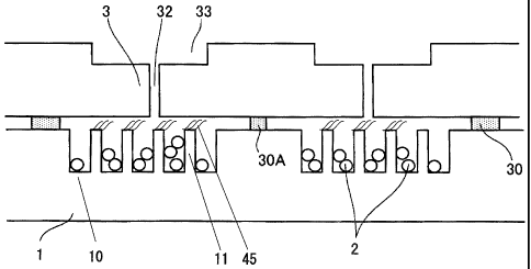
A preferred example of the relationships among the
irregular region, the cover member and the particles in the
analysis chip of the present invention will now be explained
referring to Fig. 12. In the example shown in Fig. 12, the
selective binding substance(s) 45 such as DNA is(are)
immobilized on the upper surfaces of the protruded portions 11
of the substrate 1. The particles (spherical beads, in this
case) 2 are placed in the void of the recessed portion of the
substrate 1. The selective binding substance(s) 45 and the
particles 2 contact the solution containing the test substance
(not shown). The test substance solution is retained in the
void defined by the substrate 1, the adhesive member 30 and the
cover member 3. In the example in Fig. 12, the shortest
distance between the upper surface of the protruded portion of
the substrate and the cover member 3 is less than the diameter
of the particles 2. By this, the particles are not allowed to
contact the upper surfaces of the protruded portions 11, so
that damaging of the selective binding substance(s) 45 on the
upper surface of the protruded portion 11 may be prevented. In
cases where the particle is in a nonspherical shape such as an ,
oval shape, the particles are similarly not allowed to contact
the upper surface of the protruded portion 11 as long as the
shortest distance between the upper surface of the protruded
portion and the container is less than the smallest diameter of
CA 02671866 2009-06-08
37
,the particle, so that damaging of the selective binding
substance(s) 45 may be prevented.
[0087]
Such an analysis chip of the present invention may be used
for analyses of various test substances. That is, a test
substance is brought into contact with the substrate of the
present invention on which a selective binding substance(s)
is(are) immobilized, and the test substance is allowed to
selectively bind to the selective binding substance(s),
followed by assaying of presence/absence or the quantity of the
test substance bound to the substrate via the selective binding
substance(s), to analyze the test substance.
[0088]
Examples of the test substance which may be subjected to
the method for measurement using the analysis chip of the
present invention include, but not limited to, nucleic acids to
be measured such as genes of pathogenic bacteria, viruses and
the like and causative genes of genetic diseases and the like,
and parts thereof; various biological components having
antigenecities; and antibodies to pathogenic bacteria, viruses
and the like. Examples of the samples containing such test
substances include, but not limited to, body fluids such as
blood, serum, plasma, urine, feces, spinal fluid, saliva and
various tissue fluids; various foods and beverages; and
dilutions thereof. The nucleic acid which is used as a test
substance may be one extracted from blood or cells by a
conventional method and labeled, or may be one amplified by a
nucleic acid-amplification method such as PCR using the nucleic
CA 02671866 2009-06-08
38
acid as the template. In the latter case, the measurement
sensitivity may be largely promoted. In cases where an
amplification product of a nucleic acid is used as the test
substance, the amplified nucleic acid can be labeled by
carrying out the amplification in the presence of a nucleoside
triphosphate labeled with a fluorescent substance or the like.
In cases where the test substance is an antigen or an antibody,
the antigen or antibody which is the test substance may be
directly labeled by a conventional method. Alternatively,
after binding the antigen or antibody which is the test
substance with the selective binding substance(s), the
substrate is washed, and a labeled antibody or antigen which
undergoes antigen-antibody reaction is reacted with the antigen
or antibody, followed by measurement of the amount of the label
bound to the substrate.
[0089]
In the method of the present invention for analysis of a
test substance, the test substance is first brought into
contact with the substrate constituting the analysis chip of
the present invention, on which substrate a selective binding
substance(s) is(are) immobilized, to allow selective binding
between the test substance and the selective binding
substance(s). That is, the test substance subjected to
labeling, amplification or the like as described above is made
to be an aqueous solution or dissolved in a buffer or the like
to provide a solution (this may be referred to as "test
substance solution" in the present specification), which is
then brought into contact with the substrate.
CA 02671866 2009-06-08
39
0
,[0090]
Contacting of the test substance with the substrate on
which the selective binding substance(s) is(are) immobilized
may be carried out by injecting the test substance, which was
made to be an aqueous solution or dissolved in an adequate
buffer to provide a solution, into the irregular region on the
substrate using a conventional instrument such as a pipette.
[0091]
Before injecting the test substance solution into the
analysis chip of the present invention to bring the solution
into contact with the substrate on which the selective binding
substance(s) is(are) immobilized, the solution is preferably
subjected to a degassing treatment since this may effectively
prevent generation of bubbles. Preferred examples of the
method used for the degassing treatment include known methods
such as a method wherein degassing is carried out using a
vacuum pump or an aspirator to reduce pressure, a method
wherein degassing is carried out by centrifugation, a method by
ultrasonication, and a method by heating. Among these, a
method wherein degassing is carried out using an aspirator or a
vacuum pump to reduce pressure is more preferably used as an
easy and simple method. The degree of vacuum in such cases may
be one which does not cause bumping of the solution, and a
pressure of 10 hPa (hectopascal) to 300 hPa, preferably 20 hPa
to 200 hPa, more preferably 50 hPa to 100 hPa is used. The
time for the degassing operation is preferably 2 minutes to 1
hour, more preferably 3 minutes to 30 minutes, still more
preferably 5 minutes to 20 minutes.
CA 02671866 2009-06-08
[0092]
When the analysis chip of the present invention is used,
the test substance may be applied through the penetrating hole
in the cover member, and the sealing member may be attached to
5 the cover member to seal the penetrating hole, followed by
selectively binding the test substance to the substrate
constituting the analysis chip.
[0093]
Application of the test substance through the penetrating
10 hole may be carried out, for example, by injection through the
penetrating hole with a conventional instrument such as a
pipette.
[0094]
Attaching of the sealing member to the cover member may be
15 carried out in a manner wherein a part or all of, preferably
all of, the penetrating holes are sealed. Preferred examples
of the sealing member include flexible tapes such as adhesive
tapes made of a polyimide film such as KAPTON (registered
trademark of Du Pont-Toray Co., Ltd.) and adhesive tapes made
20 of polyester, cellophane, vinyl chloride or the like, but the
sealing member is not restricted thereto, and an arbitrary
member which is non-flexible, plate-like and adhesive may be
employed, or a shapeless sealing agent may be employed. From
the view point of obtaining a better effect of the present
25 invention by the liquid level-halting chamber, a flexible tape
or a plate-like member is preferred and, from the view point of
simplicity of operation and the like, a flexible tape is more
preferred. In cases where a tape or a plate-like member is
CA 02671866 2009-06-08
41
. employed, the number of the member used is arbitrary.
Specifically, all the penetrating holes on the cover member may
be sealed with a single sealing member, or 2 or more sealing
members may be employed, each of which members may be used to
seal a part of the 2 or more sealing members. In cases where 2
or more cover members are provided on a single substrate as
above, separate sealing members may be used for the individual
cover members, or the penetrating holes on the 2 or more cover
members may be sealed with a single sealing member at once.
Usually, usage of one sealing member per one cover member is
preferred since this may achieve simple and secure sealing.
[0095]
Specific examples of sealing will now be explained
referring to Fig. 12. In the example shown in Fig. 12, after
application of the test substance solution (not shown) through
the penetrating hole 32, a flexible adhesive tape 34 which is
the sealing member is attached so as to cover the entire
surface of the liquid level-halting chamber 33 to seal the
penetrating holes. With such an embodiment, sealing, which is
simple and does not cause leakage of the test substance
solution and measurement errors, may be achieved.
[0096]
In the analytical method of the present invention,
selective binding means the process wherein the selective
binding substance and the test substance are allowed to
interact with each other to bind the test substance, via the
selective binding substance, to the substrate on which the
selective binding substance is immobilized. In the cases of
ak 02671866 2009-06-08
42
. the analysis chip of the present invention, since the particles
move within the test substance solution by the weight,
vibration and centrifugal force caused by moving and/or
rotating of the chip, the selective binding may be allowed to
proceed efficiently.
[0097]
The reaction temperature and time for carrying out the
selective binding are selected appropriately depending on the
chain length of the nucleic acid of the test substance to be
hybridized or the type(s) of the antigen and/or antibody
involved in the immunoreaction, and in the cases of
hybridization of nucleic acids, they are usually about 40 C to
70 C for 1 minutes to ten and several hours, and in the cases
of immunoreaction, they are usually about room temperature to
50 C for 1 minute to several hours. The substrate on which the
selective binding substance(s) is(are) immobilized may be moved
and/or rotated as required to promote the selective binding.
[0098]
The analysis chip of the present invention may efficiently
stir the test substance solution by moving the particles during
hybridization. Preferred examples of the method for moving the
particles include a method wherein the analysis chip is rotated
to make the particles fall to the direction of gravity; a
method wherein the analysis chip containing the particles is
placed on a shaker to shake or move the substrate; and a method
wherein magnetic particles are used and the particles are moved
by magnetic force. More preferably, a method wherein the chip
is placed on a shaker and subjected to swirling rotation in a
CA 02671866 2009-06-08
43
horizontal plane is used since, in such a case, the moving
range of the particles is large and the particles move evenly,
which results in an efficient stirring of the solution. In
such a case, the number of revolution of the swirling rotation
is preferably 10 to 1000 revolutions/minute, more preferably
100 to 500 revolutions/minute.
[0099]
After finishing the selective binding, the chip may be
usually subjected to the next step following removal of the
cover member.
[0100]
In the analytical method of the present invention, the
above described selective binding is followed by measurement of
the mass of the test substance bound to the substrate via the
selective binding substance. This measurement may also be
carried out in exactly the same manner as in the operation with
the conventional analysis chip. For example, the mass of the
test substance appropriately fluorescence-labeled and bound to
the selective binding substance may be measured by reading of
its fluorescence intensity with a known scanner or the like.
[0101]
In the analytical method of the present invention, in
cases where a nucleic acid is immobilized as the selective
binding substance, a nucleic acid having a sequence
complementary to this nucleic acid or to a part thereof may be
measured. In cases where an antibody or an antigen was
immobilized as the selective binding substance, an antigen or
antibody which immunologically reacts with this antibody or
CA 02671866 2009-06-08
44
,antigen may be measured. As used herein, "measurement"
includes both detection and quantification.
EXAMPLES
[0102]
The present invention will now be explained in more detail
by way of Examples below. The present invention is not
restricted to the Examples below.
[0103]
Example 1
(1) Preparation of Substrate for Analysis Chip
Using the LIGA (Lithographie Galvanoformung Abformung)
process which is a known method, a mold for injection molding
was prepared, and a substrate made of polymethyl methacrylate
(PMMA) having a shape as described later was obtained by
injection molding. The average molecular weight of the PMMA
used was 50,000, and carbon black (#3050B produced by
Mitsubishi Chemical) was included therein at a proportion of 1%
by weight to make the substrate black. Results of measurement
of the spectral reflectance and spectral transmittance of this
black substrate showed not more than 5% of the spectral
reflectance at any wavelength within the visible wavelength
region (400 nm to 800 nm) and not less than 0.5% of
transmittance within the same range of the wavelength. Both
the spectral reflectance and the spectral transmittance did not
show a specific spectral pattern (such as a peak) within the
visible wavelength region, and the spectrum was evenly flat.
The spectral reflectance was measured with specular reflection
CA 02671866 2009-06-08
from the substrate using a device (CM-2002 produced by Minolta
Camera) having an illumination/light-receiving optical system
satisfying the condition C of JIS Z 8722.
[0104]
5 The substrate used (hereinafter referred to as "substrate
A") had the shape exemplified in Fig. 3 and Fig. 4 and external
dimensions of a longitudinal length of 76 mm, a lateral length
of 26 mm and a thickness of 1 mm. At the center of the
substrate, a recessed portion (corresponding to the recessed
10 portion 10 in Fig. 3) having dimensions of a longitudinal
length of 39.4 mm, a lateral length of 19.0 mm and a depth of
0.15 mm was provided, in which recessed portion 9248 protruded
portions (corresponding to the protruded portions 11 in Fig. 3)
having a diameter of 0.1 mm and a height of 0.15 mm were
15 provided. In this substrate A, the difference in height
between the upper surfaces of the protruded portions
(corresponding to the protruded portions 11 in Fig. 3) and the
upper surface of the flat area (corresponding to the protruded
portion 13) (the average height of the protruded portions) was
20 not more than 3 pm. Variation in height of the upper surface
of the protruded portion (corresponding to the protruded
portion 13) (difference between the height of the highest part
of the upper surface of the protruded portion and the height of
the lowest part of the upper surface of the protruded portion)
25 was not more than 3 pm. The pitch between the protruded
portions (L1 in Fig. 4; distance between the center of a
protruded portion and the center of an adjacent protruded
portion) was 0.5 mm.
CA 02671866 2009-06-08
46
[0105]
The above substrate A was immersed in aqueous lON sodium
hydroxide solution at 70 C for 12 hours. This was washed
sequentially with pure water, 0.1N HC1 solution, and pure water,
and carboxyl groups were formed on the surface of the substrate.
(2) Immobilization of Selective Binding Substances
Each of oligonucleotides was immobilized on the substrate
A as the selective binding substances (probe DNAs) under the
following condition. The DNA microarray oligonucleotide set
"Homo sapiens (human) ARCS V4.0 (60 bases each)" produced by
Operon Biotechnologies was used as the oligonucleotides. These
oligonucleotides were dissolved in pure water to a final
concentration of 0.3 nmol/pL and used as stock solutions. When
the stock solution was spotted on the substrate, it was 10-fold
diluted with PBS (prepared by combining 8 g of NaC1, 2.9 g of
Na2HPO4.12H20, 0.2 g of KC1 and 0.2 g of KH2PO4, dissolving
thereof in pure water to attain a final volume of 1 L, and then
adjusting pH of the resulting solution to 5.5 by addition of
hydrochloric acid) to attain a final concentration of 0.03
nmol/pL for the probe DNA, in which solution 1-ethy1-3-(3-
dimethylaminopropyl)carbodiimide (EDC) was added to a final
concentration of 50 mg/mL to allow condensation between the
carboxyl group formed on the surface of the substrate made of
PMMA and the terminal amino group of the probe DNA. The
solutions were respectively spotted on the upper surfaces of
all the protruded portions of the substrate A using an arrayer
(spotter) (Gene Stamp-II produced by Nippon Laser & Electronics
Lab.). Subsequently, the spotted substrate was incubated in a
ak 02671866 2009-06-08
47
, plastic container at 37 C and a humidity of 100% for about 20
hours. Finally, the substrate was washed with pure water and
dried by centrifugation using a spin drier.
[0106]
(3) Attachment of Cover Member to Analysis Chip Substrate
The cover member was attached as follows to the substrate
A on which the selective binding substances were immobilized.
[0107]
A PMMA flat plate with dimensions of a longitudinal length
of 41.4 mm, a lateral length of 21 mm and a thickness of 1 mm
was prepared by cutting and used as the cover member. The
penetrating holes and the liquid level-halting chambers were
provided in the prepared cover member as exemplified in 32 and
33 in Fig. 7. A double-stick tape with a width of 1 mm was
used as the adhesive member, and was attached along the
longitudinal fringe of 41.4 mm and the lateral fringe of 21 mm
such that the tape was laminated at a thickness of 50 pm, to
attach the cover member to the substrate A.
[0108]
(4) Surfactant-coating of Surface of Particles for Stirring
In a stainless steel vat (10cm x 10cm x Scm), 10 g of
particles made of zirconia having a diameter of 180 pm
(produced by Toray Industries, Inc.) were placed, and 50 mL of
aqueous 0.1% sodium dodecyl sulfate (SDS) solution was added
thereto as the surfactant. After sonication for 10 minutes,
the supernatant (SDS component) was removed, and the particles
were dried at 70 C for 12 hours using an oven. The surface
roughness of the particle before the treatment was 165 nm in
CA 02671866 2009-06-08
48
, terms of the centerline average roughness (Ra) of its surface.
The measurement of the Ra value of the surface of the particle
was carried out with an electron scanning microscope (ESA-2000
produced by Elionix Co., Ltd.) after vacuum deposition of Au on
its surface. The centerline average roughness was measured for
arbitrarily selected 10 particles at a magnification of x10,000
and with a cut off value of 0, and the average value was
calculated.
[0109]
(5) Injection (Containing) of Particles in Analysis Chip and
Evaluation of Operability of Injection (Containing)
In the substrate A to which the cover member was attached
in the above (3), 120 mg of the particles made of zirconia
coated with the surfactant in the above (4) was injected
(contained) in the void formed by the substrate A and the cover
member (the recessed portion of the irregular region of the
surface of the substrate A). Injection of the particles was
carried out through the penetrating hole of the cover member
(the penetrating hole 32 exemplified in Fig. 7 or Fig. 12).
The thus obtained analysis chip is hereinafter referred to as
"analysis chip 1".
[0110]
Here, operability of injection of the particles into the
analysis chip was evaluated as follows. When 120 mg of the
particles were injected, the operability was evaluated as "A"
in cases where the time required for the injection was less
than 3 minutes since the operation was very easy; it was
evaluated as "B" in cases where the time required for the
CA 02671866 2009-06-08
49
, injection was not less than 3 minutes and less than 5 minutes
since the operation was relatively easy; and it was evaluated
as "C" in cases where the injection of the whole quantity of
the particles was not accomplished within 5 minutes since the
operation was difficult or not easy.
[0111]
The operability of injection of the particles in the
analysis chip 1 was "A" (Table 1).
[0112]
(6) Preparation of Test Substance DNA
As the test substance, aRNA (antisense RNA) which is
common as a test substance was used. From 5pg of the total RNA
(Human Reference RNA produced by CLONTECH) which is
commercially available and was derived from human cultured
cells, 5pg of Cy3-labeled aRNA was obtained using an aRNA
preparation kit produced by Ambion.
[0113]
In the present Example, the following Examples and the
Comparative Examples, the test substance solution used for
hybridization was one prepared by diluting the above prepared
labeled aRNA with a solution of 1 wt% BSA, 5 x SSC, 0.01 wt%
salmon sperm DNA and 0.1 wt% SDS (each concentration represents
a final concentration) unless otherwise specified.
[0114]
(7) Hybridization Reaction and Evaluation of Number of
Generated Bubbles
Using a micropipette, 165 pL of the hybridization test
substance solution containing 200 ng of Cy3-labeled aRNA was
ak 02671866 2009-06-08
injected through the penetrating hole into the void (reaction
vessel) between the substrate A and the cover member of the
analysis chip 1. The solution could be easily injected at this
time, and no bubble was entrapped. Using the KAPTON tape (As
5 One Corporation) as a sealing material, 4 penetrating holes
were sealed. A hybridization chamber (Takara Hybridization
chamber (produced by Takara Bio Inc.)) was closely contacted
with and fixed to a sheet shaking platform (MMS FIT-S produced
by Tokyo Rikakikai), and the analysis chip 1 was placed in the
10 hybridization chamber. At this time, 15 pL each of ultrapure
water was dropped to recesses at the both sides of the location
where the analysis chip 1 was placed. After closing the lid of
the hybridization chamber, the chip was fixed by tightening of
6 fixation screws, and the chamber was fixed on a shaker (MMS-
15 310 produced by Tokyo Rikakikai) installed in an thermostat
chamber (FMS-1000 produced by Tokyo Rikakikai) set at 42 C.
The front side of the thermostat chamber was shaded with
aluminum foil, and the chamber was incubated with rotary
shaking at 250 revolutions/minute at 42 C for 16 hours. After
20 the incubation, the analysis chip 1 was removed from the
hybridization chamber.
[0115]
Through the cover member, bubbles in the test substance
solution observed on the substrate A of the analysis chip 1
25 were counted. Based on the results obtained by 10 runs of
hybridization reaction using the analysis chip 1, the number of
the bubbles generated in the test substance solution was 4.5 on
average per reaction (Table 1).
ak 02671866 2009-06-08
51
, [0116]
(8) Measurement of Fluorescence Signal and Evaluation of
Deviation of Detection Sensitivity
After removal of the cover member and the double-stick
tape adhered to the substrate A of the analysis chip 1, the
substrate A was washed and dried. The substrate A after the
above treatment was placed in a scanner for a DNA chip (GenePix
4000B produced by Axon Instruments), and the signal value of
the label (fluorescence intensity) of the test substance
subjected to the hybridization reaction and the background
noise were measured under a condition wherein the laser output
was 33% and the voltage setting for the photomultiplier was 500.
Among the totally 9248 spots, 32 spots were used as negative
control spots for measurement of the background fluorescence,
and the true signal value for each spot was calculated by
subtracting the background signal value from individual signal
values.
[0117]
For evaluation of deviation of the detection sensitivity
due to unevenness of the hybridization reaction, 10 runs of
hybridization reaction was carried out using the analysis chip
1, and the deviation of the background signal values (CV value
= the standard deviation of the background signal values in all
runs / the mean value of the background signal values of all
runs (%)) was calculated for each reaction. As a result, the
average of the deviations (CV values) of the background signal
values based on the 10 runs of evaluation was 8.4% (Table 1).
[0118]
CA 02671866 2009-06-08
52
. Example 2
Evaluation using the analysis chip 1 was carried out in
the same manner as in Example 1 except that the test substance
solution prepared in Example 1 (6) was subjected to a degassing
treatment as follows.
[0119]
To a 0.2 ml PCR tube (72.737.002 produced by ASSIST), 175
pL of the test substance solution was added, and the tube was
placed in a degasifier (type NDA-015 aspirator produced by
ULVAC) with the lid left open to carry out degassing of the
solution. The ultimate pressure during degassing was 50 hPa
according to indication by the apparatus, and the time period
for degassing was 25 minutes.
[0120]
In the same manner as in Example 1 (7), bubbles in the
test substance solution observed on the substrate after the
hybridization reaction were counted. The average number of the
bubbles per reaction calculated from the results obtained by 6
runs of the reaction was 0.4 (Table 1).
[0121]
Further, in the same manner as in Example 1 (8), the
deviation of the background signal values (CV value) was
calculated, and shown to be 6.7% (Table 1).
[0122]
Comparative Example 1
The "analysis chip 2" was prepared in the same manner as
in Example 1 except that the particles made of zirconia were
used as they were without being subjected to coating with a
CA 02671866 2009-06-08
53
. surfactant (Example 1 (4)). Using this analysis chip 2,
evaluation was carried out as in Example 1.
[0123]
The result of evaluation of injection operability of the
particles as in Example 1 (5) showed that inclusion of the
particles into the analysis chip 2 was difficult and the time
required exceeded 5 minutes, so that the operability was
evaluated as "C" (Table 1).
[0124]
For this analysis chip 2, bubbles generated in the test
substance solution after the hybridization reaction were
counted in the same manner as in Example 1 (7). The average
number of the bubbles calculated from the results obtained by
24 runs of the reaction was 13.0 (Table 1).
[0125]
Further, in the same manner as in Example 1 (8), the
deviation of the background signal values (CV value) was
calculated, and shown to be 12.1% (Table 1).
[0126]
Comparative Example 2
Evaluation was carried out in the same manner as in
Example 2 except that the analysis chip 2 prepared in
Comparative Example 1 was used instead of the analysis chip 1,
with a degassing treatment of the test substance solution.
[0127]
Bubbles generated after the hybridization reaction were
counted in the same manner as in Example 1 (7). The average
number obtained by 3 runs of evaluation was 9.0 (Table 1).
CA 02671866 2009-06-08
54
- [0128]
Further, in the same manner as in Example 1 (8), the
deviation of the background signal values (CV value) was
calculated, and shown to be 10.5% (Table 1).
[0129]
Example 3
In Example 1 (4), as the surfactant, sodium deoxycholate
(a kind of anionic surfactant) was used instead of sodium
dodecyl sulfate (SDS), and 120 mg of the particles subjected to
a coating treatment with the surfactant in the same manner was
injected to prepare an "analysis chip 3". Using this analysis
chip 3, evaluation was carried out with a degassing treatment
of the test substance solution as in Example 2.
[0130]
The result of evaluation of injection operability of the
particles as in Example 1 (5) showed that inclusion operability
of the particles into the analysis chip 3 was evaluated as "B"
since the average of the runs required in 10 runs of the
reaction was not less than 3 minutes and not more than 5
minutes (Table 2).
[0131]
For this analysis chip 3, bubbles generated in the test
substance solution after the hybridization reaction were
counted in the same manner as in Example 1 (7). The average
number of the bubbles calculated from the results obtained by
10 runs of the reaction was 0.6 (Table 2).
[0132]
Further, in the same manner as in Example 1 (8), the
CA 02671866 2013-08-07
.76199-290
deviation of the background signal values (CV value) was
calculated, and shown to be 7.2% (Table 1).
[0133]
Example 4
In Example ,1 (4), as the surfactant, Pluronic F68 (a kind
of nonionic surfactant) was used instead of sodium dodecyl
sulfate (SDS), and the particles subjected to a coating
treatment with the surfactant were used by the following steps
to prepare an "analysis chip 4". That is, after treating the
10 particles made of zirconia in the same manner as in Example 1
(4), the particles were washed once with 400 mL of deionized
water (Milli-dwwater) and then dried at 70 C for 4 hours. To
the analysis chip, 120 mg of these particles were injected to
prepare the analysis chip 4.
15 [0134]
By all the.results obtained by 10 runs of evaluation of
injection operability of the particles in the same manner as in
Example 1 (5), the time required was shown to be not more than
3 minutes. Thus, the operability was evaluated as "A" (Table
20 2).
[0135]
To the analysis chip 4, 165 pL of the test substance
=
solution subjected to a degassing treatment in the same manner
as in Example 2 was applied, and hybridization reactions were
25 carried out in the same manner as in Example 1 (7). The number
of bubbles generated in the test substance solution was counted,
and the average.number obtained by 6 runs of evaluation was 1.2
(Table 2).
CA 02671866 2009-06-08
56
- [0136]
Further, in the same manner as in Example 1 (8), the
deviation of the background signal values (CV value) was
calculated, and shown to be 8.4% (Table 2).
[0137]
Example 5
In Example 1 (4), as the surfactant, Pluronic F127 (a kind
of nonionic surfactant) was used instead of sodium dodecyl
sulfate (SDS), and the particles subjected to a coating
treatment with the surfactant were used by the following steps
to prepare an "analysis chip 5". That is, after treating the
particles made of zirconia in the same manner as in Example 1
(4), the particles were washed once with 400 mL of deionized
water (Milli-Q water) and then dried at 70 C for 4 hours. To
the analysis chip, 120 mg of these particles were injected to
prepare the analysis chip 5.
[0138]
By all the results obtained by 10 runs of evaluation of
injection operability of the particles in the same manner as in
Example 1 (5), the time required was shown to be not more than
3 minutes. Thus, the operability was evaluated as "A" (Table
2).
[0139]
To the analysis chip 5, 165 pL of the test substance
solution subjected to a degassing treatment in the same manner
as in Example 2 was applied, and hybridization reactions were
carried out in the same manner as in Example 1 (7). The number
of bubbles generated in the test substance solution was counted,
CA 02671866 2009-06-08
57
and the average number obtained by 6 runs of evaluation was 1.8
(Table 2).
[0140]
Further, in the same manner as in Example 1 (8), the
deviation of the background signal values (CV value) was
calculated, and shown to be 7.6% (Table 2).
[0141]
Example 6
In Example 1 (4), as the surfactant, Triton X-100 (a kind
of nonionic surfactant) was used instead of sodium dodecyl
sulfate (SDS), and the particles subjected to a coating
treatment with the surfactant were used by the following steps
to prepare an "analysis chip 6". That is, after treating the
particles made of zirconia in the same manner as in Example 1
(4), the particles were subjected to ultrasonic washing in 400
mL of deionized water (Milli-Q water) for 30 seconds and then
dried at 70 C for 4 hours. To the analysis chip, 120 mg of
these particles were injected to prepare the analysis chip 6.
[0142]
By the results obtained by 10 runs of evaluation of
injection operability of the particles in the same manner as in
Example 1 (5), the time required was shown to be not more than
3 minutes in 7 chips, and not less than 3 minutes and not more
than 5 minutes in 3 chips. Thus, the operability was evaluated
as "B" (Table 2).
[0143]
To the analysis chip 6, 165 pL of the test substance
solution subjected to a degassing treatment in the same manner
CA 02671866 2009-06-08
58
as in Example 2 was applied, and hybridization reactions were
carried out in the same manner as in Example 1 (7). The number
of bubbles generated in the test substance solution was counted,
and the average number obtained by 6 runs of evaluation was 2.1
(Table 2).
[0144]
Further, in the same manner as in Example 1 (8), the
deviation of the background signal values (CV value) was
calculated, and shown to be 8.3% (Table 2).
[0145]
Example 7
In Example 1 (4), Tween 20 (a kind of nonionic surfactant)
was used instead of sodium dodecyl sulfate (SDS) as the
surfactant, and the particles subjected to a coating treatment
with the surfactant were used by the following steps to prepare
an "analysis chip 7". That is, after treating the particles
made of zirconia in the same manner as in Example 1 (4), the
particles were washed once with 400 mL of deionized water
(Milli-Q water) and then dried at 70 C for 4 hours. To the
analysis chip, 120 mg of these particles were injected to
prepare the analysis chip 7.
[0146]
By the results obtained by 10 runs of evaluation of
injection operability of the particles in the same manner as in
Example 1 (5), the time required was shown to be not more than
3 minutes for 6 chips, and not less than 3 minutes and not more
than 5 minutes for 4 chips. Thus, the operability was
evaluated as "B" (Table 2).
CA 02671866 2009-06-08
59
, [0147]
To the analysis chip 7, 165 pL of the test substance
solution subjected to a degassing treatment in the same manner
as in Example 2 was applied, and hybridization reactions were
carried out in the same manner as in Example 1 (7). The number
of bubbles generated in the test substance solution was counted,
and the average number obtained by 6 runs of evaluation was 2.2
(Table 2).
[0148]
Further, in the same manner as in Example 1 (8), the
deviation of the background signal values (CV value) was
calculated, and shown to be 7.0% (Table 2).
[0149]
Example 8
In Example 1 (4), as the surfactant, 3-[(3-
cholamidopropyl)dimethylammonio]-2-hydroxypropanesulfonate
(CHAPSO; a kind of amphoteric surfactant) was used instead of
sodium dodecyl sulfate (SDS), and the particles subjected to a
coating treatment with the surfactant were used by the
following steps to prepare an "analysis chip 8". That is,
after treating the particles made of zirconia in the same
manner as in Example 1 (4), the particles were washed once with
400 mL of deionized water (Milli-Q water) and then dried at
70 C for 4 hours. To the analysis chip, 120 mg of these
particles were injected to prepare the analysis chip 8.
[0150]
By the results obtained by 10 runs of evaluation of
injection operability of the particles in the same manner as in
CA 02671866 2009-06-08
, Example 1 (5), the time required was shown to be not more than
3 minutes for 8 chips, and not less than 3 minutes and not more
than 5 minutes for 2 chips. Thus, the operability was
evaluated as "Be' (Table 2).
5 [0151]
To the analysis chip 8, 165 pL of the test substance
solution subjected to a degassing treatment in the same manner
as in Example 2 was applied, and hybridization reactions were
carried out in the same manner as in Example 1 (7). The number
10 of bubbles generated in the test substance solution was counted,
and the average number obtained by 6 runs of evaluation was 2.5
(Table 2).
[0152]
Further, in the same manner as in Example 1 (8), the
15 deviation of the background signal values (CV value) was
calculated, and shown to be 7.6% (Table 2).
[0153]
Example 9
In Example 1 (4), as the surfactant,
20 cetyltrimethylammonium bromide (CTAB; a kind of cationic
surfactant) was used instead of sodium dodecyl sulfate (SDS),
and the particles subjected to a coating treatment with the
surfactant were used by the following steps to prepare an
"analysis chip 9". That is, after treating the particles made
25 of zirconia in the same manner as in Example 1 (4), the
particles were washed once with 400 ml of deionized water
(Milli-Q water) and then dried at 70 C for 4 hours. To the
analysis chip, 120 mg of these particles were injected to
ak 02671866 2009-06-08
61
, prepare the analysis chip 9.
_
[0154]
By the results obtained by 10 runs of evaluation of
injection operability of the particles in the same manner as in
Example 1 (5), the time required was shown to be not more than
3 minutes for 7 chips, and not less than 3 minutes and not more
than 5 minutes for 3 chips. Thus, the operability was
evaluated as "B" (Table 2).
[0155]
To the analysis chip 9, 165 pL of the test substance
solution subjected to a degassing treatment in the same manner
as in Example 2 was applied, and hybridization reactions were
carried out in the same manner as in Example 1 (7). The number
of bubbles generated in the test substance solution was counted,
and the average number obtained by 6 runs of evaluation was 3.0
(Table 2).
[0156]
Further, in the same manner as in Example 1 (8), the
deviation of the background signal values (CV value) was
calculated, and shown to be 7.9% (Table 2).
[0157]
Example 10
In Example 1 (1), the "substrate B" which is a substrate
having only a recessed portion with dimensions of a
longitudinal length of 39.4 mm, a lateral length of 19.0 mm and
a depth of 0.05 mm (one having the same shape as exemplified in
Fig. 3 and Fig. 4 except that it does not have the protruded
portions 11) was used as the substrate of the analysis chip
ak 02671866 2009-06-08
62
, instead of the substrate A. Immobilization of the selective
binding substances in Example 1 (2) was carried out by placing
9248 spots with the same intervals as those for the substrate A
so as to form a rectangle with dimensions of a longitudinal
length of 39.4 mm and a lateral length of 19.0 mm on the bottom
surface of the recessed portion.
[0158]
As the cover member of Example 1 (3), a PMMA flat plate
with dimensions of a longitudinal length of 41.4 mm, a lateral
length of 21 mm and a thickness of 1 mm was prepared by cutting
and used. The penetrating holes and the liquid level-halting
chambers were provided in the prepared cover member as
exemplified as 32 and 33 in Fig. 7. A double-stick tape with a
width of 1 mm was used as the adhesive member, and was attached
along the longitudinal fringe of 41.4 mm and the lateral fringe
of 21 mm such that the tape was laminated at a thickness of 50
pm, to attach the cover member to the substrate B.
[0159]
Except these, by the same steps as those in (1)-(4) in
Example 1, the "analysis chip 10" into which 120 mg of the
particles made of zirconia coated with sodium dodecyl sulfate
(SDS) as the surfactant were injected was prepared.
[0160]
By all the results obtained by 10 runs of evaluation of
injection operability of the particles in the same manner as in
Example 1 (5), the time required was shown to be not less than
3 minutes and not more than 5 minutes. Thus, the operability
was evaluated as "B" (Table 3).
CA 02671866 2009-06-08
63
[0161]
To the analysis chip 10, 165 pL of the test substance
solution subjected to a degassing treatment in the same manner
as in Example 2 was applied, and hybridization reactions were
carried out in the same manner as in Example 1 (7). The number
of bubbles generated in the test substance solution was counted,
and the average number obtained by 6 runs of evaluation was 0.5
(Table 3).
[0162]
Further, in the same manner as in Example 1 (8), the
deviation of the background signal values (CV value) was
calculated, and shown to be 9.5% (Table 3).
[0163]
Example 11
In Example 1 (1), the "substrate C" which is a flat plate
having neither a recessed portion nor a protruded portion (one
having the same shape as exemplified in Fig. 3 and Fig. 4
except that it has neither the recessed portion 10 nor the
protruded portion 11) was used as the substrate of the analysis
chip instead of the substrate A. Immobilization of the
selective binding substances in Example 1 (2) was carried out
by placing 9248 spots with the same intervals as those for the
substrate A so as to form a rectangle with dimensions of a
longitudinal length of 39.4 mm and a lateral length of 19.0 mm
on the upper flat surface of the substrate C.
[0164]
As the cover member of Example 1 (3), a PMMA flat plate
with dimensions of a longitudinal length of 41.4 mm, a lateral
CA 02671866 2009-06-08
64
- length of 21 mm and a thickness of 1 mm was prepared by cutting
and used. The penetrating holes and the liquid level-halting
chambers were provided in the prepared cover member as
exemplified in 32 and 33 in Fig. 7. A double-stick tape with a
width of 1 ram was used as the adhesive member, and was attached
along the longitudinal fringe of 41.4 mm and the lateral fringe
of 21 ram such that the tape was laminated at a thickness of 200
pm, to attach the cover member to the substrate C.
[0165]
Except these, by the same steps as those in (1)-(4) in
Example 1, the "analysis chip 11" in which 120 mg of the
particles made of zirconia coated with sodium dodecyl sulfate
(SDS) as the surfactant were injected was prepared.
[0166]
By the results obtained by 10 runs of evaluation of
injection operability of the particles in the same manner as in
Example 1 (5), the time required was shown to be not more than
3 minutes for 7 chips, and not less than 3 minutes and not more
than 5 minutes for 3 chips. Thus, the operability was
evaluated as "B" (Table 3).
[0167]
To the analysis chip 11, 165 pL of the test substance
solution subjected to a degassing treatment in the same manner
as in Example 2 was applied, and hybridization reactions were
carried out in the same manner as in Example 1 (7). The number
of bubbles generated in the test substance solution was counted,
and the average number obtained by 6 runs of evaluation was 0.6
(Table 3).
CA 02671866 2009-06-08
, [0168]
Further, in the same manner as in Example 1 (8), the
deviation of the background signal values (CV value) was
calculated, and shown to be 9.3% (Table 3).
5 [0169]
Example 12
In Example 1 (4), particles made of iron with a diameter
of 200 pm (produced by Sanshokenmazai Co., Ltd.) were used as
the particles instead of the particles made of zirconia with a
10 diameter of 180 pm, and 120 mg of the particles subjected to a
coating treatment with sodium dodecyl sulfate (SDS) as the
surfactant in the same manner as in Example 1 (4) were injected
to prepare an "analysis chip 12".
[0170]
15 By all the results obtained by 10 runs of evaluation of
injection operability of the particles in the same manner as in
Example 1 (5), the time required was shown to be not less than
3 minutes and not more than 5 minutes. Thus, the operability
was evaluated as "B" (Table 3).
20 [0171]
The test substance solution subjected to a degassing
treatment in the same manner as in Example 2 was applied to the
analysis chip 12, and hybridization reactions were carried out
in the same manner as in Example 1 (7). The number of bubbles
25 generated in the test substance solution was counted, and the
average number obtained by 6 runs of evaluation was 2.2 (Table
3).
[0172]
ak 02671866 2009-06-08
66
= Further, in the same manner as in Example 1 (8), the
deviation of the background signal values (CV value) was
calculated, and shown to be 8.0% (Table 3).
[0173]
Comparative Example 3
A chip was prepared in the same manner as in Example 12
except that the particles made of iron with a diameter of 200
pm were used as they were as the particles, to prepare an
"analysis chip 13". Using this analysis chip 13, evaluation
was carried out in the same manner as in Example 1.
[0174]
By all the results obtained by 10 runs of evaluation of
injection operability of the particles in the same manner as in
Example 1 (5), the injection operation was shown to be
difficult and take more than 5 minutes. Thus, the operability
was evaluated as "C" (Table 3).
[0175]
The test substance solution subjected to a degassing
treatment in the same manner as in Example 2 was applied to the
analysis chip 13, and hybridization reactions were carried out
in the same manner as in Example 1 (7). The number of bubbles
generated in the test substance solution was counted, and the
average number obtained by 6 runs of evaluation was 10.0 (Table
[0176]
Further, in the same manner as in Example 1 (8), the
deviation of the background signal values (CV value) was
calculated, and shown to be 13.3% (Table 3).
CA 02671866 2009-06-08
67
- [0177]
Example 13
In Example 1 (4), particles made of glass with a diameter
of 200 pm (produced by Bio Medical Science Inc.) were used as
the particles instead of the particles made of zirconia with a
diameter of 180 pm, and 120 mg of the particles subjected to a
coating treatment with sodium dodecyl sulfate (SDS) as the
surfactant in the same manner as in Example 1 (4) were injected
to prepare an "analysis chip 14".
[0178]
By all the results obtained by 10 runs of evaluation of
injection operability of the particles in the same manner as in
Example 1 (5), the time required was shown to be not less than
3 minutes and not more than 5 minutes. Thus, the operability
was evaluated as "B" (Table 3).
[0179]
The test substance solution subjected to a degassing
treatment in the same manner as in Example 2 was applied to the
analysis chip 14, and hybridization reactions were carried out
in the same manner as in Example 1 (7). The number of bubbles
generated in the test substance solution was counted, and the
average number obtained by 6 runs of evaluation was 1.0 (Table
3).
[0180]
Further, in the same manner as in Example 1 (8), the
deviation of the background signal values (CV value) was
calculated, and shown to be 8.2% (Table 3).
[0181]
CA 02671866 2009-06-08
68
- Comparative Example 4
A chip was prepared in the same manner as in Example 13
except that, as the particles, those made of glass with a
diameter of 200 pm were used as they were without the coating
treatment with the surfactant (Example 1 (4)), to prepare an
"analysis chip 15". Using this analysis chip 15, evaluation
was carried out in the same manner as in Example 1.
[0182]
By all the results obtained by 10 runs of evaluation of
injection operability of the particles in the same manner as in
Example 1 (5), the injection operation was shown to be
difficult and take more than 5 minutes. Thus, the operability
was evaluated as "C" (Table 3).
[0183]
The test substance solution subjected to a degassing
treatment in the same manner as in Example 2 was applied to the
analysis chip 15, and hybridization reactions were carried out
in the same manner as in Example 1 (7). The number of bubbles
generated in the test substance solution was counted, and the
average number obtained by 6 runs of evaluation was 8.8 (Table
3).
[0184]
Further, in the same manner as in Example 1 (5), the
deviation of the background signal values (CV value) was
calculated to be 12.9% (Table 3).
CA 02671866 2009-06-08
1 69
,
. [0185] =
[Table 1]
Comparative Comparative
Example 1 Example 2
Example 1 Example 2
Analysis chip
1 1 2 2
number
Substrate A Substrate A Substrate A
Substrate A
Substrate
Treatment with
Yes Yes No No
surfactant
Surfactant SDS SDS _ _
Degassing
No Yes No Yes
treatment
Material of
Zirconia Zirconia Zirconia
Zirconia
particles
Injection
operability of A A C C
particles
Average number
of bubbles 4.5 0.4 13.0 9.0
generated
CV value (%) of
background 8.4 6.7 12.1 10.5
signals
.
[0186]
[Table 2]
Example 3 Example 4 Example 5 Example 6 Example 7 Example 8 Example 9
Analysis chip number 3 4 5 6 7 8
9
Substrate Substrate Substrate Substrate Substrate Substrate
Substrate Substrate
A A A A A A
A
Treatment with
Yes Yes Yes Yes Yes Yes
Yes
surfactant
Sodium Pluronic Pluronic Triton X-
Surfactant Tween 20
CHAPSO CTAB
deoxycholate F68 F127 100
Degassing treatment Yes Yes Yes Yes Yes Yes
Yes
Material of
Zirconia Zirconia Zirconia Zirconia Zirconia Zirconia Zirconia
particles
Injection
operability of B A A B B B
B
particles
Average number of
0.6 1.2 1.8 2.1 2.2 2.5
3.0
bubbles generated
CV value (%) of
7.2 8.4 7.6 8.3 7.0 7.6
7.9
background signals
CA 02671866 2009-06-08
[0187]
[Table 3]
Example Example Example Comparative Example Comparative
10 11 12 Example 3 13
Example 4
Analysis chip number 10 11 12 13 14
15
Substrate
Substrate Substrate Substrate Substrate Substrate Substrate
A A A
A
Treatment with
Yes Yes Yes No Yes
No
surfactant
Surfactant SDS SDS SDS SDS
Degassing treatment Yes Yes Yes Yes Yes
Yes
Material of particles Zirconia Zirconia Iron Iron Glass
Glass
Injection operability
of particles
Average number of
0.5 0.6 2.2 10.0 1.0
8.8
bubbles generated
CV value (%) of
9.5 9.3 8.0 13.3 8.2
12.9
background signals
[0188]
5 From the results in the above Examples 1-13 and
Comparative Examples 1-4, it was revealed that generation of
bubbles is suppressed by coating the surface of the particles
with a surfactant, so that deviation of data (CV value of the
background signals) may be reduced and operability of injection
10 of the particles into the analysis chip may be improved, and
that the generation of the bubbles may be more effectively
suppressed when a degassing treatment of the test substance
solution is carried out in combination with this coating.
15 INDUSTRIAL APPLICABILITY
[0189]
The present invention suppresses the deviation of
detection sensitivities and enables detection of a test
substance with high sensitivity in an analysis chip having a
20 substrate on which a selective binding substance(s) capable of
CA 02671866 2009-06-08
71
4 selectively binding to the test substance is(are) immobilized,
wherein the test substance solution may be stirred with
particles. The analysis chip provided by the present invention
is useful as an analysis chip for detection of various
biologically relevant substances in the fields of medicine and
healthcare, and also as an analysis chip for detection of trace
substances in the fields of food and environment.