Note: Descriptions are shown in the official language in which they were submitted.
CA 02672252 2009-06-10
STEAM FLOOR MOP
FIELD OF THE INVENTION
This invention relates to a steam floor mop, and specifically, to a steam
cleaning appliance for cleaning work.
BACKGROUND OF THE INVENTION
The current floor cleaning mops are generally classified into two types: one
is
the traditional floor mop which can be used for the dry cleaning work, and is
not
suitable to realize a wet cleaning purpose; therefore, its application is
limited; the
other is the floor cleaning mop having a steam distributing function, with
which the
water is firstly heated vaporized to generate steam which is then distributed
to the
floor for the cleaning work so as to realize the effect of high-temperature
disinfecting
and sterilizing. However the current steam floor mop has the following
drawbacks:
when in use, the water needs to be provided firstly to the steam generator by
powering
on the water pump additionally, and then is heated vaporized to generate steam
for the
cleaning work, this process takes such a long time that its application is
inconvenient;
in addition, the cleaning work has to be performed repeatedly many times in
order to
obtain a thorough cleaning effect, it is time-consuming and tiring. The main
reasons
for the above problems are that: most of the cleaning surface of the current
mop is flat,
which is bad for the steam distributing to the whole cleaning surface, and
thus results
in the consequence that the cleaning surface can not be wetted uniformly, some
portion of the cleaning surface is too dry while some portion is too wet, and
that, the
effect of high-temperature disinfecting and sterilizing can not be realized;
moreover,
the cleaning cloth serves to cover the floor brush is too smooth without any
pattern or
stripe that the stains adhered to the floor cannot be cleaned easily.
SUMMARY OF THE INVENTION
In view of the above-described problems, it is an objective of the present
i
CA 02672252 2009-06-10
invention to provide a steam floor mop with which the steam can be distributed
instantaneously to the floor brush so as to perform the cleaning work by only
pushing
the handle of the steam floor mop.
It is another objective of the present invention, to provide a steam floor mop
with which the cleaning work can be performed conveniently and is time and
labor
saving, and the effect of high temperature disinfecting and sterilizing can be
realized
thoroughly.
To achieve the above objectives, the invention provides a steam floor mop
comprising a handle; a body inside which a manual water pump, a water tank,
and a
steam generator are provided; and a floor brush connected movably to the body,
wherein the manual water pump, the water tank, the steam generator and the
floor
brush are connected by means of pipes; said handle is connected directly to
the piston
rod in the manual water pump and serves to manipulate the operation of the
manual
water pump; and said floor brush is covered by a cleaning cloth.
In accordance with the steam floor mop of the present invention, a buffer area
is provided at a central steam inlet mouth of the floor brush, a plurality of
rib stripes is
extended from the center of the buffer area, a plurality of steam distributing
grooves is
formed between the rib stripes, and a peripheral edge is set around a rim of
the floor
brush.
In accordance with the steam floor mop of the present invention, said manual
water pump comprises a pump body, the piston rod, a water pump inlet mouth, a
water pump outlet mouth, a one-way inlet pump core, and a one-way outlet pump
core;
and a piston cavity of the pump body is a stepped cavity where a upper cavity
of the
piston cavity has a larger diameter than the lower cavity of the piston
cavity.
In accordance with the steam floor mop of the present invention, said steam
generator comprises a conical shell and a heating core; a water inlet mouth is
provided
on a bottom end of the heating core, a plurality of electrical heating bodies
is die cast
2
CA 02672252 2009-06-10
in the heating core and a handstand conical cavity is formed inside the
heating core, a
steam collection room is provided inside the conical shell and is positioned
opposite
to the conical cavity formed by the inner wall of the shell, a slidable steam
separating
cover is located between the steam collection room and the heating core, a
steam
collecting mouth for connecting the conical cavity to the steam collection
room is
provided at the center of the steam separating cover, a steam exit is provided
at a top
end of the steam collection room, and a plurality of C-shaped guide rings is
set at the
water inlet mouth on a bottom end of the heating core.
In accordance with the steam floor mop of the present invention, said cleaning
cloth is matchable with the floor brush and is served to cover tightly the
floor brush,
and a plurality of #-shaped grilles is formed on the surface of the cleaning
cloth.
In accordance with the steam floor mop of the present invention, the height of
the peripheral edge of said floor brush is 0.5-2mm higher than that of the rib
stripes.
In accordance with the steam floor mop of the present invention, said cleaning
cloth is in a shape of vest, a pair of fixing straps is extended from a upper
portion of
the cleaning cloth, a plurality of magic female tapes is affixed on the fixing
straps,
and a plurality of magic male tapes that can be pasted fixed with the said
magic
female tapes respectively is affixed on a lower portion of the cleaning cloth.
In accordance with the steam floor mop of the present invention, a handle
cover that can socket with the handle is located on a top end of said body,
and the
upper end of said handle cover is fixed on the body.
In accordance with the steam floor mop of the present invention, the one-way
inlet pump core and the one-way outlet pump core of said water pump are in a
shape
of flat cone having a top structure that can be opened after an elastic
deformation.
In accordance with the steam floor mop of the present invention, a steam inlet
mouth is also provided on said floor brush, and is connected to the water
outlet mouth
of the steam generator.
3
CA 02672252 2009-06-10
As a result, in accordance with the steam floor mop of the present invention,
by only pushing the handle of the steam floor mop, the steam can be generated
and
instantaneously distributed to the floor brush so that the cleaning work
having an
effect of high temperature disinfecting and sterilizing can be realized. It is
not
needed to power on the water pump additionally so as to supply water to the
steam
generator to generate the steam. Besides, a plurality of rib stripes is set on
the floor
brush, and a plurality of steam distributing grooves is formed between the rib
stripes,
so that the steam can be distributed uniformly to the whole cleaning surface
of the
floor brush. In addition, the floor brush is covered tightly by a cleaning
cloth having
a plurality of #-shaped grills formed thereon, so that the stains adhered to
the floor can
be cleaned easily. Therefore, by utilizing the steam floor mop of the present
utility
model, the cleaning work can be performed conveniently and is time and labor
saving,
the effect of high temperature disinfecting and sterilizing can be realized
thoroughly.
BRIEF DISCRIPTION OF THE DRAWINGS
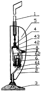
FIG I is a schematic view of a steam floor mop of the present invention;
FIG. 2 is a sectional view of a steam floor mop of the present invention;
FIG. 3 is a top view of a floor brush for a steam floor mop of the present
invention;
FICx 4 is a bottom view of the floor brush for the steam floor mop of the
present invention;
FIG 5 is a perspective view of the floor brush for the steam floor mop of the
present invention;
FIG 6 is an A-A sectional view of FIG. 3;
FIG 7 is an enlarged view of portion B of FIG. 6 of the present invention;
FIG. 8 is a planar view of a cleaning cloth for a steam floor mop of the
present
4
CA 02672252 2009-06-10
invention;
FIG 9 is a perspective view of a water pump for a steam floor mop of the
present invention;
FIG 10 is a sectional view of FIG. 9 of the present invention; and
FIG 11 is a structural view of a steam generator for a steam floor mop of the
present invention.
List of reference numerals:
I handle 11 handle cover
2 body
3 floor brush 33 steam inlet mouth
34 buffer area 35 rib strips
36 steam distributing grooves 37 peripheral edge
4 manual water pump 41 piston rod
42 water pump inlet mouth 43 water pump outlet mouth
44 one-way inlet pump core 45 one-way outlet pump core
46 piston cavity 47 pump body
5 water tank
6 steam generator 61 water inlet mouth
62 steam exit 63 conical shell
64 heating core 65 electrical heating body
66 conical cavity 67 steam collection room
68 steam separating cover 69 steam collecting mouth
641 C-shaped guide ring
7 cleaning cloth 71 fixing strap
72 magic female tape 73 magic male tape
A first pipe B second pipe
C third pipe
5
CA 02672252 2009-06-10
DETAILED DESCRIPTION OF THE INVENTION
As shown in FIGS. 1-2, a steam floor mop comprises a handle 1, a body 2
inside which a manual water pump 4, a water tank 5, and a steam generator 6
are
provided; and a floor brush 3 connected movably to the bottom end of the body
2,
wherein said handle I is connected directly to a piston rod 41 in the manual
water
pump 4, and serves to manipulate the operation of the manual water pump 4;
said
floor brush 3 is covered with a cleaning cloth 7. A water pump inlet mouth 42
and a
water pump outlet mouth 43 are formed at the lower end of said manual water
pump 4,
wherein said water pump inlet mouth 42 is connected to the water tank 5 by
means of
a first pipe A; said water pump outlet mouth 43 is connected to a water inlet
mouth 61
of the steam generator 6 by means of a second pipe B; a steam exit 62 of the
steam
generator 6 is connected to the floor brush 3 by means of a third pipe C.
During
performing the cleaning work using the steam floor mop, by only pushing the
handle
I of the steam floor mop, the piston rod 41 at the top end of the manual water
pump 4
is pushed by the handle 1; water is fed into the steam generator 6 by means of
the
manual water pump 4, and then is heated vaporized to generate steam by the
steam
generator 6; the generated steam firstly flows into the floor brush 3 by the
third pipe C,
and then flows into the cleaning cloth 7 covered on the floor brush 3; the
cleaning
work having an effect of high temperature disinfecting and sterilizing can be
realized
by using the steam with the cleaning cloth 7. It is not needed to power on the
water
pump additionally so as to supply water to the steam generator to generate the
steam.
A handle cover 11 that can socket with the handle 1 and serves to limit the
moving range of the handle I is also located on a top end of the body 2, and
the upper
end of the handle cover 11 is fixed on the body 2.
As shown in FIGS. 3-7, the floor brush 3 is a fan-shaped brush, a steam inlet
mouth 33 is further provided at the floor brush 3, and is connected to the
water outlet
mouth 62 of the steam generator 6 by means of the third pipe C. A buffer area
34 is
provided around the center steam inlet mouth 33 of the floor brush 3 and
serves
6
CA 02672252 2009-06-10
mainly to buffer the pressure and speed of the steam in order to guide
smoothly the
flow of the steam. A plurality of rib strips 35 is extended from the center of
the
buffer area 34 and a plurality of steam distributing grooves 36 is formed
between the
rib stripes. In this way, the steam can be distributed uniformly to the whole
cleaning
surface of the floor brush, the excessive steam can be vented out and thus the
excessive moisture of the cleaning cloth 7 can be avoided. Besides, a
peripheral
edge 37 is set around the rim of the floor brush 3, and is 0.5-2 mm higher
than the rib
stripes 35.
As shown in. FIGS. 9-10, the manual water pump 4 comprises a pump body
47, a piston rod 41, a water pump inlet mouth 42, a water pump outlet mouth
43, a
one-way inlet pump core 44, and a one-way outlet pump core 45. A piston cavity
46
of said pump body 47 is a stepped cavity, where the upper cavity has a larger
diameter
than the lower cavity. The one-way inlet and outlet pump cores 44, 45 are made
of
elastic material and have a top structure that can be opened after an elastic
deformation so as to form a two-layered anti-backpressure apparatus, thereby
to
against the backpressure of the steam generator 6, and thus to prevent the
pump cores
from being broken down by the backpressure of the steam generator 6, as well
as to
control the one-way flow of the water. Namely, the manual water pump 4 can be
regarded us a one-way automatic artificial intelligent feed pump, and by
pushing the
handle 1 of the steam floor mop, the piston rod 41 of the manual water pump 4
can be
operated to push automatically the pump water to the steam generator 6.
As shown in FIG 11, the steam generator 6 comprises a conical shel163 and a
heating core 64, wherein a water inlet mouth 61 is formed at the bottom end of
the
heating core 64, and a plurality of electrical heating bodies 65 is die cast
and a
handstand conical cavity 66 is formed inside the heating core 64; a steam
collection
room 67 is provided inside the conical shell 63 and is positioned opposite to
the
conical cavity 66; a slidable steam separating cover 68 is located between the
steam
collection room 67 and the heating core 64, a steam collecting mouth 69 for
7
CA 02672252 2009-06-10
connecting the conical cavity 66 to the steam collection room 67 is provided
at the
center of the steam separating cover 68, and a steam exit 62 is provided on
the top end
of said steam collection room. In addition, a plurality of C-shaped guide
rings 641 is
set at the water inlet mouth 61 on a bottom end of the heating core 64, and is
served to
separate the flow of the water in order to distribute the water uniformly to
the whole
surface of the heating core.
As shown in FIG. 8, the cl eaing cloth 7 is in a shape of vest, a pair of
fixing
straps 71 is extended from the upper portion of the cleaning cloth 7; a magic
female
tape 72 is affixed on each of said fixing straps 71, a pair of magic male
tapes 73 that
can be pasted fixed with the magic female tapes 72 is affixed on a lower
portion of the
cleaning cloth 7. The size of the cleaning cloth 7 that is matchable with the
size of
the floor brush is applied to cover the floor brush 3 tightly. A plurality of
#-shaped
grilles are formed on the surface of the cleaning cloth so that the stains
adhered on the
floor can be cleaned easily. The cleaning cloth 7 covered at the upper portion
of the
floor brush 3 is applied to encase the excessive steam and thusly two sides
thereof are
heated; the cleaning cloth that covered on the lower portion of the floor
brush 3 is
used for cleaning the floor.
As stated above, a plurality of rib strips 35 is provided at the floor brush
and a
plurality of steam distributing grooves 36 is formed between the rib stripes
35, so that
the steam can be distributed uniformly to each corner of the floor brush, and
the
humidity can be balanced. As a result, by using the cleaning cloth formed with
#-shaped grilles thereon and covering the floor brush 3 tightly, a cleaning
work can be
performed conveniently and is time and labor saving, and the effect of high
temperature disinfecting and sterilizing can be realized.
s