Note: Descriptions are shown in the official language in which they were submitted.
CA 02672460 2012-02-02
LOCATION OF WIDEBAND OFDM TRANSMITTERS WITH LIMITED RECEIVER
BANDWIDTH
TECHNICAL FIELD
[0002] The present invention relates generally to the field of wireless
communications,
and more specifically to the location of wireless devices within the coverage
area of a wireless
communications network. Wireless devices, also called mobile stations (MS),
include those such
as used in analog or digital cellular systems, personal communications systems
(PCS), enhanced
specialized mobile radios (ESMRs), wide-area-networks (WANs), and other types
of wireless
communications systems. This field is now generally known as wireless
location, and has
application for Wireless E911, fleet management, RF optimization, security,
and other valuable
applications.
BACKGROUND
A. Wireless Location
[0003] Early work relating to Wireless Location Systems is described in U.S.
Patent
No. 5,327,144, July 5, 1994, "Cellular Telephone Location System," which
discloses a system
for locating cellular telephones using time difference of arrival (TDOA)
techniques. This and
other exemplary patents (discussed below) are assigned to TruePosition, Inc.,
the assignee of the
present invention.
1
CA 02672460 2009-06-11
WO 2008/073706 PCT/US2007/085735
[0004] The `144 patent describes what may be referred to as an uplink-time-
difference-
of-arrival (U-TDOA) cellular telephone location system. The described system
may be
configured to monitor control channel transmissions from one or more cellular
telephones and to
use central or station-based processing to compute the geographic location(s)
of the phone(s).
For example, in station-based processing, which may be employed for reverse
control channel
signal detection, cross-correlations are performed at the cell sites (or
signal collection systems) in
the following manner: For each "strong" signal, which may be considered a
reference signal,
received on a particular control channel at a particular first cell site, that
strong signal is first
applied to a signal decoder, such as that used by the cellular system itself.
This decoder
demodulates the cellular signal to produce the original digital bit stream
which had been
modulated to produce the cellular signal. This digital bit stream is then
modulated by the cell site
system to reconstruct the original signal waveform as it was first transmitted
by the cellular
telephone. This reconstructed signal waveform is cross-correlated against the
received signal at
the first cell site. The cross-correlation produces a peak from which an exact
time of arrival can
be calculated from a predetermined point on the peak. The first cell site
system then sends the
demodulated digital bit stream and the time of arrival to the central site
over the communications
line. The central site then distributes the demodulated digital bit stream and
the exact time of
arrival to other cell sites likely to have also received the cellular
transmission. At each of these
other second, third, fourth, etc., cell sites, the digital bit stream is
modulated by the cell site
system to reconstruct the original signal waveform as it was first transmitted
by the cellular
telephone. This reconstructed signal waveform is cross-correlated against the
signal received at
each cell site during the same time interval. The cross-correlation may or may
not produce a
peak; if a peak is produced, an exact time of arrival (TOA) can be calculated
from a
predetermined point on the peak. This TOA is then sent to the central site,
and a delay difference,
or TDOA, for a particular pair of cell sites can be calculated. This method
permits the cell site
systems to extract TOA information from an extremely weak signal reception,
where the weak
signal may be above or below the noise level. This method is applied
iteratively to sufficient
pairs of cell sites for each strong signal received at each cell site for each
sample period. The
results of the delay pairs for each signal are then directed to the location
calculation algorithm.
[0005] TruePosition and others (e.g., KSI, Inc.) have continued to develop
significant
enhancements to the original inventive concepts. Some examples are discussed
below.
[0006] U.S. Patent No. 6,047,192, April 4, 2000, "Robust, Efficient,
Localization
System," is another example of a prior art patent describing a similar process
(referred to as
"matched-replica processing") for processing mobile transmitter signals to
determine location
related signal parameters, which may be employed to calculate the transmitter
location.
2
CA 02672460 2009-06-11
WO 2008/073706 PCT/US2007/085735
[0007] Another exemplary prior art patent is U.S. Patent No. 6,091,362, July
18, 2000,
"Bandwidth Synthesis for Wireless Location System." This patent describes a
system and
process offering improved accuracy of location information and greater time
resolution. In the
described system, signals transmitted by wireless telephones are received at a
plurality of signal
collection sites. To improve the accuracy of the location information, the
system synthesizes
greater bandwidth, and thus greater time resolution, than would otherwise be
available. The
location system can issue commands to cause a wireless transmitter to be
located to change
frequency channels, and a doubly-differenced carrier phase of the transmitted
signal, or the
TDOA, is observed at each of many frequencies spanning a wide bandwidth. The
phase-
measurement data from these many frequencies are combined to resolve the
inherent integer-
wavelength ambiguity. The invention may be utilized to obtain a bandwidth
greater than the
typical bandwidth of the signals to be cross-correlated (in either the time or
frequency domains)
in a cellular telephone location application.
[0008] Another example is U.S. Patent No. 6,646,604, November 11, 2003,
"Automatic
Synchronous Tuning of Narrowband Receivers of a Wireless Location System for
Voice/Traffic
Channel Tracking." This patent describes a transmitter locating method that
involves performing
location processing on signals received during an automatic sequential tuning
mode of operation,
wherein narrowband receivers are tuned sequentially and in unison to a
plurality of predefined
RF channels. Signal transmissions of interest in these channels are digitally
recorded and used in
location processing. The identity of the located transmitter(s) is determined
by matching a
location record to data indicating which wireless transmitters were in use at
a time corresponding
to the location record, and which cell sites and RF channels were used by each
wireless
transmitter.
[0009] An example of a wireless location system (WLS) of the kind described
above is
depicted in Figure 1. As shown, the system includes four major subsystems: the
Signal
Collection Systems (SCS's) 10, the TDOA Location Processors (TLP's) 12, the
Application
Processors (AP's) 14, and the Network Operations Console (NOC) 16. Each SCS is
responsible
for receiving the RF signals transmitted by the wireless transmitters on both
control channels and
voice channels. In general, an SCS (now sometimes called an LMU, or Location
Measuring
Unit) is preferably installed at a wireless carrier's cell site, and therefore
operates in parallel to a
base station. Each TLP 12 is responsible for managing a network of SCS's 10
and for providing
a centralized pool of digital signal processing (DSP) resources that can be
used in the location
calculations. The SCS's 10 and the TLP's 12 operate together to determine the
location of the
wireless transmitters. Both the SCS's 10 and TLP's 12 contain a significant
amount of DSP
resources, and the software in these systems can operate dynamically to
determine where to
3
CA 02672460 2009-06-11
WO 2008/073706 PCT/US2007/085735
perform a particular processing function based upon tradeoffs in processing
time,
communications time, queuing time, and cost. Each TLP 12 exists centrally
primarily to reduce
the overall cost of implementing the WLS. In addition, the WLS may include a
plurality of SCS
regions each of which comprises multiple SCS's 10. For example, "SCS Region 1"
includes
SCS's 10A and 10B that are located at respective cell sites and share antennas
with the base
stations at those cell sites. Drop and insert units 11A and 11B are used to
interface fractional
T1/E1 lines to full T1/E1 lines, which in turn are coupled to a digital access
and control system
(DACS) 13A. The DACS 13A and another DACS 13B are used in the manner described
more
fully below for communications between the SCS's 10A, 10B, etc., and multiple
TLP's 12A,
12B, etc. As shown, the TLP's are typically collocated and interconnected via
an Ethernet
network (backbone) and a second, redundant Ethernet network. Also coupled to
the Ethernet
networks are multiple AP's 14A and 14B, multiple NOC's 16A and 16B, and a
terminal server
15. Routers 19A and 19B are used to couple one WLS to one or more other
Wireless Location
System(s).
B. Evolving Wireless Standards and Air Interface Protocols
[0010] Over the past few years, the cellular industry has increased the number
of air
interface protocols available for use by wireless telephones, increased the
number of frequency
bands in which wireless or mobile telephones may operate, and expanded the
number of terms
that refer or relate to mobile telephones to include "personal communications
services,"
"wireless," and others. The air interface protocols now used in the wireless
industry include
AMPS, N-AMPS, TDMA, CDMA, GSM, TACS, ESMR, GPRS, EDGE, UMTS WCDMA, and
others. UMTS is a wideband CDMA air interface protocol defined by ETSI 3GPP.
This protocol
is similar to the CDMA protocols in EIA/TIA IS-95, or CDMA 2000, but does not
require
synchronization of the base stations, and also provides a high level of
interoperability with GSM
network infrastructure.
[0011] Orthogonal Frequency Division Multiplexing (OFDM) is a multiplexing
technique in which a given subscriber may be assigned many frequency channels
over which it
will simultaneously transmit. The multiplexing scheme provides high bandwidth
efficiency and
broadband wireless communication in a high multi-path environment. WiFi as
defined in IEEE
802.11 and WiMax as defined in IEEE 802.16 utilize OFDM. It is expected that
IEEE 802.20
(when re-ratified) will utilize OFDM.
[0012] Uplink TDOA location of fourth generation (4G) broadband OFDM signals
with
bandwidths that can exceed 20 MHz requires expensive receiver and signal
processing hardware.
The SCSs (or LMUs) may be required to receive, sample, store and process these
broadband
4
CA 02672460 2012-03-30
signals, making the hardware significantly more expensive than what is
required for third
generation (3G) signals, such as UMTS or CDMA 2000 WCDMA signals occupying a
bandwidth of 3-5Mhz. As described in greater detail below, a goal of the
present invention is to
provide a way to accomplish U-TDOA location on the broadband 4G waveforms by
collecting
and processing only a portion of the transmitted signal, reducing the required
bandwidth,
memory, and digital signal processing required in the SCS/LMU, while still
achieving high
accuracy.
SUMMARY
[0013] The following summary is intended to explain several aspects of the
illustrative
embodiments described in greater detail below. This summary is not intended to
cover all
inventive aspects of the disclosed subject matter, nor is it intended to limit
the scope of
protection of the claims set forth below.
[0014] One illustrative embodiment of the present invention takes the form of
a system
for locating wireless transmitters employing an Orthogonal Frequency Division
Multiplexing
(OFDM) digital modulation scheme. The OFDM scheme comprises transmitting
signal
components over a plurality of predefined narrowband frequency channels
spanning a predefined
wideband channel. The system includes a first receiving system configured to
receive a fraction
of the signal components transmitted by a first wireless transmitter to be
located in a fraction of
the predefined narrowband frequency channels, and to process the fraction of
the signal
components to derive location related measurements. The system further
includes at least a
second receiving system configured to receive the said fraction of the signal
components
transmitted by the first wireless transmitter, and to process this said
fraction of the signal
components to derive location related measurements. The system also includes a
processing
system configured to use location related measurements from the first and
second receiving
systems to compute the location of the wireless transmitter.
[0014a] More specifically, in one embodiment, a system for locating wireless
transmitters employing an Orthogonal Frequency Division Multiplexing (OFDM)
digital
modulation scheme is described, where the OFDM scheme includes transmitting
signal
components over a plurality of narrowband frequency channels spanning a
wideband channel.
A first receiving system is configured to receive a fraction of the signal
components transmitted
by a first wireless transmitter to be located in a fraction of the narrowband
frequency channels,
and to process the fraction of the signal components to derive location
related measurements.
The fraction of the narrowband frequency channels includes at least one pilot
channel
CA 02672460 2012-03-30
in which the first wireless transmitter transmits energy. The first receiving
system is
configured to use signal components in the pilot channel to aid in signal
acquisition and
demodulation. The first receiving system includes a first frequency conversion
circuit
configured to convert a first received RF signal component to a first digital
baseband OFDM
signal. A Fast Fourier Transform (FFT) circuit is configured to perform an FFT
of the first
digital baseband OFDM signal provided by the first frequency conversion
circuit. A
demodulation circuit is configured to produce coded bits based on the output
of the FFT
circuit. A first reconstruction circuit is configured to reconstruct the first
digital baseband
OFDM signal based on the coded bits produced by the demodulation circuit. A
first
correlation processing system is configured to correlate the first
reconstructed digital baseband
OFDM signal with the first digital baseband OFDM signal. A correlation
function peak is
indicative of a first time of arrival for the first received RF signal
component.
[0014b] A second receiving system is configured to receive the fraction of the
signal components transmitted by the first wireless transmitter, and to
process the fraction of
the signal components to derive location related measurements. The second
receiving system
is configured to use signal components in the pilot channel to aid in signal
acquisition and
demodulation. The second receiving system includes a second reconstruction
circuit
configured to receive the coded bits produced by the first demodulation
circuit of the first
receiving system and to produce the first reconstructed digital baseband OFDM
signal. A
second correlation processing system is configured to correlate the first
reconstructed digital
baseband OFDM signal with a second digital baseband OFDM signal derived by the
second
receiving system. A peak of the correlation function is indicative of a second
time of arrival
for the RF signal as received at the second receiving system.
[0014c] A processing system, operatively coupled to the first and second
receiving systems, is configured to use location related measurements from the
first and second
receiving systems, including the first and second times of arrival, to compute
the location of
the first wireless transmitter.
[0014d] In another embodiment, a method for locating wireless transmitters
employing an Orthogonal Frequency Division Multiplexing (OFDM) digital
modulation
scheme is described, where the OFDM scheme includes transmitting signal
components over a
plurality of narrowband frequency channels spanning a wideband channel. At a
first receiving
system, a fraction of the signal components transmitted by a first wireless
transmitter to be
located in a fraction of the narrowband frequency channels is received and
processed to derive
location related measurements including a first time of arrival for a first
received RF signal
5a
CA 02672460 2012-03-30
component. The processing at the first receiving system includes converting
the first received
RF signal component to a first digital baseband OFDM signal, performing a Fast
Fourier
Transform (FFT) of the first digital baseband OFDM signal provided by the
first frequency
conversion circuit, producing coded bits based on the output of the FFT
circuit, reconstructing
the first digital baseband OFDM signal based on the coded bits, and
correlating the
reconstructed first digital baseband OFDM signal with the first digital
baseband OFDM signal,
wherein a correlation function peak is indicative of the first time of arrival
for the first received
RF signal component.
[0014e] At a second receiving system which is geographically separated from
the
first receiving system, the fraction of the signal components transmitted by
the first wireless
transmitter is received and processed to derive location related measurements
including a
second time of arrival for the RF signal as received at the second receiving
system. The
processing at the second receiving system includes receiving the coded bits
produced by the
first receiving system and producing the first reconstructed digital baseband
OFDM signal and
correlating the first reconstructed digital baseband OFDM signal with a second
digital
baseband OFDM signal derived by the second receiving system. A peak of the
correlation
function is indicative of a second time of arrival for the RF signal as
received at the second
receiving system.
[0014f] The location related measurements are processed from the first and
second receiving systems to compute the location of the wireless transmitter.
The fraction of
the narrowband frequency channels includes at least one pilot channel in which
the first
wireless transmitter transmits energy, and where the first and second
receiving systems use
signal components in the pilot channel for signal acquisition and
demodulation.
[0014g] In another embodiment, a non-transitory computer readable medium
comprising executable instructions for use by a receiving system deployed in a
system for
locating wireless transmitters employing an Orthogonal Frequency Division
Multiplexing
(OFDM) digital modulation scheme is described, where the OFDM scheme includes
transmitting signal components over a plurality of predefined narrowband
frequency channels
spanning a predefined wideband channel, the computer readable medium
comprising
executable instructions for causing a receiving system to carry out a method.
At a first
receiving system, a fraction of the signal components transmitted by a first
wireless transmitter
to be located in a fraction of the narrowband frequency channels is received
and processed to
derive location related measurements including a first time of arrival for a
first received RF
signal component. The processing at the first receiving system includes
converting the first
5b
CA 02672460 2012-03-30
received RF signal component to a first digital baseband OFDM signal,
performing a Fast
Fourier Transform (FFT) of the first digital baseband OFDM signal provided by
the first
frequency conversion circuit, producing coded bits based on the output of the
FFT circuit,
reconstructing the first digital baseband OFDM signal based on the coded bits,
and correlating
the reconstructed first digital baseband OFDM signal with the first digital
baseband OFDM
signal. A correlation function peak is indicative of the first time of arrival
for the first received
RF signal component.
[0014h] At a second receiving system which is geographically separated from
the
first receiving system, the fraction of the signal components transmitted by
the first wireless
transmitter is received and processed to derive location related measurements
including a
second time of arrival for the RF signal as received at the second receiving
system. The
processing at the second receiving system includes receiving the coded bits
produced by the
first receiving system and producing the first reconstructed digital baseband
OFDM signal and
correlating the first reconstructed digital baseband OFDM signal with a second
digital
baseband OFDM signal derived by the second receiving system. A peak of the
correlation
function is indicative of a second time of arrival for the RF signal as
received at the second
receiving system.
[0014i] The location related measurements from the first and second receiving
systems are processed to compute the location of the wireless transmitter. The
fraction of the
narrowband MHz frequency channels includes at least one pilot channel in which
the first
wireless transmitter transmits energy, and the first and second receiving
systems use signal
components in the pilot channel for signal acquisition and demodulation.
[0014j] In another embodiment, a network-based system for locating wireless
transmitters employing an Orthogonal Frequency Division Multiplexing (OFDM)
digital
modulation scheme is described, where the OFDM scheme comprises transmitting
signal
components over a plurality of narrowband frequency channels spanning a
wideband channel,
where the narrowband frequency channels have a bandwidth on the order of 3-5
MHz and the
wideband channel has a bandwidth on the order of 20 MHz A first receiving
system is
configured to receive a fraction of the signal components transmitted by a
first wireless
transmitter to be located in a fraction of the narrowband 3-5MHz frequency
channels, where
the fraction of the narrowband 3-5 MHz frequency channels includes at least
one pilot channel
in which the first wireless transmitter transmits energy. The first receiving
system includes a
first frequency conversion circuit configured to convert a first received RF
signal component to
a first digital baseband OFDM signal having a sample rate which is
substantially lower than
5c
CA 02672460 2012-03-30
the 48 MHz required to properly sample a 20 MHz signal. The first frequency
conversion
circuit includes a filter bandwidth which is substantially less than 20 MHz. A
Fast Fourier
Transform (FFT) circuit is configured to perform an FFT of the first digital
baseband OFDM
signal provided by the first frequency conversion circuit. A demodulation
circuit is configured
to produce coded bits based on the output of the FFT circuit. A first
reconstruction circuit is
configured to reconstruct the first digital baseband OFDM signal based on the
coded bits
produced by the demodulation circuit. The first reconstruction circuit is
configured to
modulate the coded bits into one of PSK or QAM symbols, and to perform an
inverse FFT
(IFFT) of the symbols to produce a first reconstructed digital baseband OFDM
signal. A first
correlation processing system is configured to correlate the first
reconstructed digital baseband
OFDM signal with the first digital baseband OFDM signal. A correlation
function peak is
indicative of a first time of arrival (TOA) for the first received RF signal
component.
[0014k] A second receiving system is configured to receive the fraction of the
signal components transmitted by said first wireless transmitter. The second
receiving system
includes a second reconstruction circuit configured to receive the coded bits
produced by the
first demodulation circuit of the first receiving system and to produce the
first reconstructed
digital baseband OFDM signal. A second correlation processing system is
configured to
correlate the first reconstructed digital baseband OFDM signal with a second
digital baseband
OFDM signal derived by the second receiving system. A peak of the correlation
function is
indicative of a second time of arrival (TOA) for the RF signal as received at
the second
receiving system.
[00141] A processing system is operatively coupled to the first and second
receiving systems. The processing system is configured to use the first and
second TOA
values from the first and second receiving systems to compute the location of
the wireless
transmitter.
[0015] Other aspects of the embodiments disclosed herein are described below.
BRIEF DESCRIPTION OF THE DRAWINGS
[0016] The foregoing summary as well as the following detailed description are
better understood when read in conjunction with the appended drawings. For the
purpose of
illustrating the invention, there is shown in the drawings exemplary
constructions of the
invention; however the invention is not limited to the specific methods and
instrucmentalities
disclosed. In the drawings:
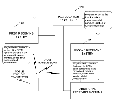
[0017] Figure 1 schematically depicts a Wireless Location System.
5d
CA 02672460 2009-06-11
WO 2008/073706 PCT/US2007/085735
[0018] Figures 2A and 2B are block diagrams of the signal processing in OFDM
transmitters and receivers, respectively.
[0019] Figure 3 illustrates a reduced spectrum processed by a SCS or LMU as
compared with the entire spectrum transmitted.
[0020] Figure 4 schematically depicts an exemplary signal processing chain
employed
by the SCSs of an illustrative embodiment.
[0021] Figure 5 is a block diagram of a modified signal processing chain
employed to
support a reduced signal bandwidth.
[0022] Figure 6 is a block diagram of a reconstruction process for the reduced
signal.
[0023] Figure 7 is a flowchart of a station-based location process for the
reduced signal.
[0024] Figure 8A depicts an ideal cross-correlation function showing peaks due
to two
signal components, a direct path component and a delayed component due to a
multi-path
reflection.
[0025] Figure 8B depicts an ideal cross-correlation function (solid line)
showing peaks
due to two signal components and a band-limited cross-correlation function
showing the
smearing of those peaks that make them indistinguishable.
[0026] Figure 8C depicts an ideal cross-correlation function (solid line)
showing peaks
due to two signal components and a band-limited cross-correlation function,
with 4x the
bandwidth of the function shown in Figure 8B, still showing some smearing, but
the increased
bandwidth makes two individual peaks distinguishable.
[0027] Figure 9 illustrates the full bandwidth of an OFDM waveform with small
slices
processed at any one time by an SCS/LMU, with multiple time intervals used to
cover most or all
of the OFDM waveform bandwidth.
[0028] Figure 10 schematically depicts a Wireless Location System for locating
OFDM
transmitters in accordance with an illustrative embodiment.
DETAILED DESCRIPTION OF ILLUSTRATIVE EMBODIMENTS
[0029] We will now describe illustrative or presently preferred embodiments of
the
present invention. First, we provide an overview and then a more detailed
description.
A. Overview
[0030] The present invention may be embodied in various forms, e.g., as a
system,
method, or computer readable medium bearing executable instructions for
carrying out the
inventive process. For example, a system in accordance with the present
invention may be
implemented as a system for locating wireless transmitters employing an
Orthogonal Frequency
Division Multiplexing (OFDM) digital modulation scheme. The illustrative
system is shown
6
CA 02672460 2009-06-11
WO 2008/073706 PCT/US2007/085735
schematically in Figure 10. The OFDM scheme comprises transmitting signal
components over a
plurality of narrowband frequency channels spanning a wideband channel. The
system includes
first and second receiving systems (elements 100 and 101 in Figure 10), which
may take the
form of an SCS or LMU co-located at a base transceiver station of a wireless
communications
system, although this is by no means required. The receiving systems are each
configured to
receive a fraction of the signal components transmitted by a wireless
transmitter to be located
(element 120 in Figure 10) in a fraction of the narrowband frequency channels,
and to process
the signal components to derive location related measurements. These
measurements are then
provided to a processing system (element 110) configured to use the location
related
measurements to compute the location of the wireless transmitter. The
processing system may
take the form of a TLP of the kind referred to above, although this is not
required.
[0031] The location related measurements derived by the receiving systems may
comprise measurements of time difference of arrival (TDOA), time of arrival
(TOA), angle of
arrival (AOA), round trip time, power, or another form of measurement that may
be used to
calculate the location of the wireless transmitter.
[0032] The fraction of the narrowband frequency channels received by the
receiving
systems may include at least one pilot channel in which the wireless
transmitter transmits energy,
and the receiving systems may be configured to use signal components in the
pilot channel to aid
in signal acquisition and demodulation. Moreover, the fraction of the
narrowband frequency
channels may exclude guard channels in which the wireless transmitter
transmits minimal
energy.
[0033] The receiving systems may each include a radio frequency (RF) filter,
and they
are preferably each configured to receive signal components within a bandwidth
compatible with
the RF filter. The receiving systems may also include an intermediate
frequency (IF) filter, and
are preferably configured to receive signal components within a bandwidth
compatible with the
IF filter. In addition, the receiving systems may each include an analog to
digital converter
(ADC) characterized by a sample rate, and are preferably configured to receive
signal
components within a bandwidth compatible with the sample rate. The ADCs may be
characterized by a sample rate after decimation, and the receiving systems may
be configured to
receive signal components within a bandwidth compatible with the sample rate
after decimation.
The receiving systems may also include available memory for storing data
representing received
signal components, and may be configured to receive signal components within a
bandwidth
compatible with the available memory. The receiving systems may also include
digital signal
processors (DSPs) characterized by DSP processing throughput, and may be
configured to
receive signal components within a bandwidth compatible with the DSP
processing throughput.
7
CA 02672460 2009-06-11
WO 2008/073706 PCT/US2007/085735
[0034] The receiving systems may be configured to receive signal components
within a
bandwidth compatible with a current load on the receiving system. For example,
the amount of
DSP processing available within the receiving system (e.g., SCS) at any point
in time may be a
function of the location processing load on the system. If the load happens to
be lower, and
adequate DSP processing resources are available, then a wider portion of the
transmitted
bandwidth could be processed. However, if the load on the receiving system is
high, a smaller
portion of transmitted bandwidth would be processed to reduce the processing
load on the DSP
resources.
[0035] The receiving systems may also be configured to tune to a plurality of
channels
to receive signals from a plurality of wireless transmitters to be located. In
addition, the receiving
systems may be configured to tune to a plurality of selected channels, wherein
the selected
channels are determined based upon interference levels. For example, higher
interference could
reduce the ability for receiving systems (e.g., LMUs) to detect signals, and
could reduce the
accuracy of computed locations. In general, it is better to select the portion
of transmitted
spectrum that is least used by other transmitters. The level of interference
over different sections
of the transmitted signal can be determined by making power measurements at
the receiving
system, and/or by using the knowledge of the channels used by other
transmitters in the network.
The wireless network itself should have knowledge of the spectrum utilization.
[0036] The selected channels may be determined based upon various factors,
including
but not limited to measurements of received signals and spectrum usage.
[0037] A bandwidth synthesis process may also be advantageously employed in
connection with the present invention.
[0038] Moreover, use of the present invention may also involve use of a
sequential or
random pattern of re-tuning a frequency agile receiver to cover most or all of
the OFDM
waveform spectrum.
[0039] In addition, a station-based or central processing method may be
advantageously
used in practicing the invention.
B. Location of broadband OFDM transmitters with TDOA, using only a portion of
the
transmitted spectrum
[0040] Broadband wireless communication infrastructure is being deployed and
used
on a large scale basis. WiFi capable devices, as defined in IEEE 802.11G, are
capable
communicating at rate of 54 mbps using a signal bandwidth on the order of 20
MHz. WiMAX
capable devices as defined in IEEE 802.16 will be capable of communicating at
rate of 75 mbps,
with signal bandwidth on the order of 20 MHz. This broadband capability will
allow higher
8
CA 02672460 2009-06-11
WO 2008/073706 PCT/US2007/085735
throughput applications to be used by wireless devices. Robust location
techniques such as U-
TDOA are needed for these mobile devices for emergency and other location
based services.
[0041] Orthogonal frequency-division multiplexing (OFDM), also sometimes
called
discrete multitone modulation (DMT), is based upon the principle of frequency-
division
multiplexing (FDM), but is often used as a digital modulation scheme. The bit
stream that is to
be transmitted is split into several parallel bit streams, typically dozens to
thousands, and the
available frequency spectrum is divided into several sub-channels, and each
low-rate bit stream
is transmitted over one sub-channel by modulating a sub-carrier using a
standard modulation
scheme, for example PSK, QAM, etc. The sub-carrier frequencies are chosen so
that the
modulated data streams are orthogonal to each other, meaning that cross-talk
between the sub-
channels is eliminated. Channel equalization is simplified by using many
slowly modulated
narrowband signals instead of one rapidly modulated wideband signal. An
advantage of OFDM
is its ability to cope with severe channel conditions, such as multipath and
narrowband
interference, without complex equalization filters. As mentioned, OFDM has
developed into a
popular scheme for wideband digital communication systems.
[0042] In OFDM, the sub-carrier frequencies are chosen so that the modulated
data
streams are orthogonal to each other, meaning that cross-talk between the sub-
channels is
eliminated and inter-carrier guard bands are not required. This greatly
simplifies the design of
both the transmitter and the receiver without a separate filter for each sub-
channel, which is
required in conventional FDM. The orthogonality also allows high spectral
efficiency, near the
Nyquist rate. The orthogonality also allows for efficient modulator and
demodulator
implementation using the FFT algorithm. Although the principles and some of
the benefits have
been known since the 1960s, OFDM is made popular today for wideband
communication by
availability of low-cost digital signal processing components that can
efficiently calculate the
FFT. OFDM requires accurate frequency synchronization in the receiver; any
inaccuracy means
that the sub-carriers no longer appear orthogonal, resulting in degraded
performance.
[0043] U-TDOA location of devices transmitting these signals becomes a
challenge, as
receivers are needed to capture very high bandwidth signals, store and process
them. The
requirements for RF signal bandwidth, digital signal processing power, and
memory required to
perform U-TDOA location on a signal with a 20 MHz bandwidth signal can be six
times that
required to locate third generation (3G) wireless devices utilizing signals
with a bandwidth of 3
to 5 MHz. These increased requirements can dramatically increase the cost and
complexity of the
Signal Collection System or LMU (the terms SCS and LMU will be used
interchangeably
herein).
9
CA 02672460 2009-06-11
WO 2008/073706 PCT/US2007/085735
[0044] With an embodiment of the present invention, TDOA location of a
broadband
wireless transmitter is accomplished by selecting only a portion of the
spectrum of the
transmitted signal, which can be supported by the available capability of the
SCSs measuring the
signal. The capability includes the level of receiver bandwidth, signal
sampling rate, DSP
processing throughput, and memory. As an example, a SCS may be equipped with
an RF
receiver containing filters with sufficient bandwidth to support a 3GPP UMTS
waveform (3-5
MHz bandwidth), analog to digital converters capable of sampling a 3-5 MHz
wide signal, and
digital signal processing resources and memory capable of performing TDOA
location
processing of a signal with 3-5 MHz of bandwidth, but with the SCS incapable
of collecting and
processing a full 20MHz bandwidth signal. In this case, a contiguous portion
of the transmitted
signal may be selected, with this portion having a signal bandwidth that is
within the capabilities
of the SCS. This signal reduction is possible because the OFDM waveform
transmitted by a
broadband device actually consists of many (256 for example) contiguous
channels, which can
be individually demodulated and separated from the rest of the signal. A block
of 64 channels,
which might be selected to be a power of 2 for FFT efficiency, may be
processed in the TDOA
location computation. In a direct sequence spread spectrum system such as IS-
95, or UMTS, this
would not be possible, as there would be no way to extract any meaningful data
from a small
portion of the transmitted signal. A small portion of the spectrum could not
be demodulated
without the rest of the signal as in an OFDM waveform. Because these are high
bandwidth
signals, a station-based process as defined in the `144 patent could be used
as this minimizes the
amount of data transferred, although signal data could be transferred to a
central node for central
correlation processing, as also described in the `144 patent. This technique
applies to both
wideband and narrowband embodiments of the SCS.
[0045] The transmitted waveform used in the IEEE 802.16 WiMAX system consists
of
256 channels. The outer 55 channels are guard channels in which minimal energy
is transmitted.
In addition, there are 8 pilot channels to aid in signal acquisition and
demodulation. Selection of
the bandwidth to process should include a number of pilot channels which are
placed through the
full channel set to help the receiver properly detect and demodulate the
signal. In addition, the
guard signals are good candidates to exclude as they contain little useful
signal energy. The
channel set selection could also be based upon knowledge of the current
utilization of the
spectrum, where less utilized spectrum is chosen for processing to minimize
the likelihood of
interference. The selected channel set may also be chosen to be a power of 2
or 4 to allow for
efficient multiplexing with an FFT.
[0046] A transmitted OFDM waveform is typically constructed as shown in Figure
2A.
The process may be summarized as follows:
CA 02672460 2009-06-11
WO 2008/073706 PCT/US2007/085735
1. Information bits are encoded with additional redundant and parity bits to
allow the
receiver to detect and correct errors. (Reference numeral 20.)
2. Data are interleaved to distribute the redundant bits over a larger time to
allow the
redundancy in the error correction codes to correct short degradations in
received signal
quality. (Reference numeral 21.)
3. The encoded bits are modulated into PSK or QAM symbols, in the form of base-
band
sample data. (Reference numeral 22.)
4. A block of PSK or QAM symbols (256) are passed through an inverse Fast
Fourier
Transform (IFFT) creating the OFDM signal. (Reference numeral 23.)
5. The digital signal is then converted to analog with a digital to analog
converter.
(Reference numeral 24.)
6. The signal is frequency converted to Radio Frequency (RF) and then it is
transmitted.
(Reference numeral 25.)
[0047] A typical OFDM receiver performs the following steps shown in Figure
2B.
This process is essentially the reverse of the transmitter process:
1. RF signal is frequency converted to base-band, filtered, and digitized.
(Reference
numerals 26 and 27.) This may include:
a. One more stages of frequency conversion of the analog signal to and
intermediate
frequency (IF), or base-band;
b. Filtering of the analog signal to a bandwidth which satisfies the Nyquist
criteria
for the signal bandwidth, and sample rate;
c. Digitizing base-band or IF signal with an analog to digital converter;
d. Digital down-conversion of IF to base-band if necessary; and
e. Possible additional digital filtering, and decimation to a lower sample
rate.
2. Receiver performs an FFT of a block (256) of samples, which converts the
OFDM signal
into a single channel high data rate signal. (Reference numeral 28.)
3. Receiver demodulates PSK or QAM signals and outputs coded bits. (Reference
numeral
29.)
4. Signal is de-interleaved. (Reference numeral 30.)
5. Encoded bits are decoded, providing original information bits. (Reference
numeral 31.)
[0048] Figure 3 shows how only a portion of the transmitted channels of an
OFDM
signal is selected for location processing.
11
CA 02672460 2009-06-11
WO 2008/073706 PCT/US2007/085735
[0049] Figure 4 shows the signal processing chain of the SCS. In an
illustrative
example of the present invention, the SCS has RF signals from antennas
connected to the input.
These RF signals may contain some undesired out of band signals from the base
station
transmitter, or other interferers. The RF filter 40 reduces the levels of the
undesired signals
outside of the pass-band of the desired signals, while allowing the pass-band
signals to pass to
the next stage with minimal loss. The filtered RF signal is then frequency
converted 41 to an IF
frequency of around 70 MHz. The frequency conversion process is accomplished
by modulating
the RF signal with a sinusoidal Local Oscillator (LO) signal with a frequency
about 70 MHz
lower than the desired RF frequency. This will cause the RF signal to be
translated to frequency
around 70 Hz. Adjusting the LO frequency will allow different portions of the
LO frequency to
be tuned around 70 MHz. In this case the desired portion of the receiver RF
signal will be tuned
to a center frequency of 70 MHz.
[0050] The IF signal is then passed through an IF filter 42 to reduce the
bandwidth of
the signal such that it can easily be sampled at a rate meeting the Nyquist
criteria to avoid
aliasing. The IF filter 42 has a pass-band of 5 MHz and a center frequency of
70 MHz. The filter,
which could be made up of one or more cascaded surface acoustic wave (SAW)
filters, reduces
the power level of all signals outside of a 10 MHz bandwidth by 75 dB,
relative to the pass-band
level. A filter of this type is selected because many transceivers are
designed with a 70 MHz IF
frequency, and filters with a 5MHz pass-band are commonly used in WCDMA and
cable TV
equipment. These filters are inexpensive and readily available. Passing a
wider bandwidth of 20
MHz would likely require a custom filter design, and increase the SCS cost.
The filtered IF
signal is then sampled by the analog to digital converter 43, with a sample
rate of 60 MSPS. A
high sampling rate permits the use of digital down converters with output
signal sample rates of
-12 MSPS. The digitized signal is then passed through a digital down converter
44, where the
digital signal is filtered to a bandwidth of <5 MHz, and converted from IF to
base-band. In this
process the sample rate is also decimated to 12 MSPS. The decimation
eliminates the redundant
samples, reducing the processing load on the DSP 45.
[0051] The largest savings from reducing the processes spectrum is in memory
and
DSP processing throughput. The required memory and DSP throughput can be
compared when
performing a TDOA measurement on the full 20 MHz signal, which would have a
sample rate of
48 MHz vs. a 5 MHz portion of the signal, with a sample rate of 12 MHz. TDOA
measurements
are made by performing a cross correlation of the signal received by one SCS
with a reference
signal received at another SCS, as a function of time difference, as shown
below.
y(2) _ YN x(2)r(n +,c)
12
CA 02672460 2009-06-11
WO 2008/073706 PCT/US2007/085735
where x(n) is the received signal, r(n) is the reference signal, and N is the
number of
samples in both the received and reference signals.
[0052] Both the size of memory required to store the signal, as well as the
number of
multiplications to perform the correlation are a linear function of the number
of samples. If one
second of received and reference data are to be used for correlation, the full
signal would require
the storage of 48 million samples, and 48 million multiplications to compute a
single cross-
correlation value. The reduced signal would require storage of 12 million
samples, and 12
million multiplications to compute a single correlation value. The reduced
signal requires only 1/4
the memory and DSP 45 power as the full signal.
[0053] Figure 5 shows the demodulation and decoding by the primary SCS in a
station-
based processing implementation. Because much of the underlying data is
missing due to the
reduction in processed spectrum, the steps of interleaving and decoding are
not feasible, and are
eliminated, further reducing required processing.
1. RF signal is frequency converted to base-band, filtered, and digitized.
(Reference
numerals 50 and 51.) This may include:
a. One more stages of frequency conversion of the analog signal to and
intermediate
frequency (IF), or baseband;
b. Filtering of the analog signal to a bandwidth which satisfies the Nyquist
criteria
for the signal bandwidth, and sample rate,
i. The sample rate is be much lower than the 48MHz required to properly
sample a 20MHz signal;
ii. The filter bandwidth could be much less than the 20 MHz required to pass
an entire signal;
c. Digitizing base-band or IF signal with an analog to digital converter;
d. Digital down-conversion of IF to base-band if necessary;
e. Possible additional digital filtering, and decimation to a lower sample
rate;
2. FFT performed on of a block (64) of samples. (Reference numeral 52.)
3. PSK or QAM signals demodulated to coded bits. (Reference numeral 53.)
[0054] The reconstruction process used for the reduced signal is shown in
Figure 6.
1. The encoded bits are modulated into PSK or QAM symbols, in the form of base-
band
sample data. (Reference numeral 60.)
2. A block of PSK or QAM symbols (256) are passed through an inverse Fast
Fourier
Transform (IFFT) creating the OFDM signal. (Reference numeral 61.)
13
CA 02672460 2009-06-11
WO 2008/073706 PCT/US2007/085735
3. Additional characteristics are applied to the signal, such as phase
corrections. (Not
shown.)
[0055] Therefore, the station-based TDOA location process for the reduced
waveform
would be as shown in Figure 7:
1. The primary SCS, as well as cooperating SCSs receive and digitize the
transmitted signal
(reference numeral 70):
a. Sampling of the receive signals is synchronized to facilitate TDOA
processing.
b. Sampled signal bandwidth and sample rate may be reduced, as only a fraction
of
the signal bandwidth will be processed.
2. The primary SCS implements the demodulation steps above, which excludes de-
interleaving and error correction decoding, and also measures other signal
characteristics,
such as phase corrections. (Reference numeral 71.)
3. Encoded bits and characteristic data is transferred to cooperating SCSs.
(Reference
numeral 72.)
4. Primary and cooperating SCSs reconstruct the reference base-band signal, by
implementing the steps shown in Figure 6. (Reference numeral 73.)
5. Primary and cooperating SCSs perform correlation processing to measure the
Time
Difference of Arrival of the signal, and send the TDOA measurement to the TLP.
(Reference numeral 74.)
6. TLP computes the location. (Reference numeral 75.)
[0056] The concepts described herein are not limited to WiFi or WiMAX systems,
but
apply to any system which uses OFDM for communication. The invention is not
limited to the
specific architecture and/or implementation defined for the SCS.
Alternate Embodiments
[0057] An extension to the above approach allows the use of a narrower-band
front end
to capture just a portion of the OFDM waveform spectrum as described above,
while maintaining
the improved multi-path resolution that can be achieved using the wider-band
waveform that is
transmitted by the mobile device. This extension involves sampling a portion
of the OFDM
waveform spectrum as described above for a interval of time, then re-tuning
the frequency agile
receiver to sample a different portion of the OFDM waveform spectrum in the
next interval of
time, then continuing this process to get multiple slices of the OFDM waveform
spectrum (up to
covering the entire OFDM waveform spectrum with a series of narrow-band
samples). This re-
tuning can be performed in sequential or random patterns to cover most or all
of the OFDM
14
CA 02672460 2012-02-02
waveform bandwidth. This is illustrated in Figure 9. (See also, U.S. Patent
No. 6,646,604,
November 11, 2003, "Automatic Synchronous Tuning of Narrowband Receivers of a
Wireless
Location System for Voice/Traffic Channel Tracking.."
[0058] The ability to resolve multi-path components in the cross-correlation
function
used to measure TDOA values is limited by the bandwidth of the signal that is
used. When there
is a direct path signal and a delayed signal that arrives in close proximity
in time, an ideal
correlation function using infinite bandwidth signals would result in two
peaks that are easily
resolvable as shown in Figure 8A. When band limited signals are used to
generate the cross-
correlation function, these peaks are "smeared" by a smoothing function whose
width is
proportional to the inverse of the bandwidth of the signal. When this inverse
bandwidth is wider
then the separation between the arriving signals, they become
indistinguishable as shown in
Figure 8B. If, however, this inverse bandwidth is narrower then the separation
between the
arriving signals, then the peaks in the correlation function, while still
smeared, can be easily
distinguished, as shown in Figure 8C, where the bandwidth is 4 times that of
the signal in Figure
8B. The ability to distinguish the different signal arrivals allows the
selection of the direct path
signal. This provides a more accurate TDOA measurement, directly reducing
error of the
location estimate.
[0059] This advantage of a wider bandwidth cross-correlation function can be
achieved
without the added cost of sampling the full bandwidth simultaneously, which
would require a
wider-band front receiver, higher sample rate A/D converter, more storage, and
processing
power. Instead, a series of narrow-band samples can be stored, and the
advantage of the wider
bandwidth cross-correlation function can be achieved using the bandwidth
synthesis process
described in U.S. Patent No. 6,091,362, July 18, 2000, "Bandwidth Synthesis
for Wireless
Location System."
[0060] In frequency hopped waveforms such as GSM, the advantage gained by
performing bandwidth synthesis can be somewhat limited by the fact that the
spacing of the
sampled frequency is not contiguous in general, and can be quite sparse in
practice. This sparse
spacing results in ambiguities in the synthesized cross-correlation function
that may not be
successfully resolved. In this embodiment, the OFDM waveform occupies a large
contiguous
block of spectrum which is sampled using a series of narrower slices of the
spectrum. This
insures that the slices will be adjacent to each other in frequency (see
Figure 9), allowing the
bandwidth synthesis process to produce a synthesized cross-correlation
function that does not
contain ambiguities.
CA 02672460 2009-06-11
WO 2008/073706 PCT/US2007/085735
C. Conclusion
[0061] The true scope the present invention is not limited to the presently
preferred
embodiments disclosed herein. For example, the foregoing disclosure of a
presently preferred
embodiment of a Wireless Location System uses explanatory terms, such as
Signal Collection
System (SCS), TDOA Location Processor (TLP), Applications Processor (AP),
Location
Measuring Unit (LMU), and the like, which should not be construed so as to
limit the scope of
protection of the following claims, or to otherwise imply that the inventive
aspects of the
Wireless Location System are limited to the particular methods and apparatus
disclosed.
Moreover, as will be understood by those skilled in the art, many of the
inventive aspects
disclosed herein may be applied in location systems that are not based on TDOA
techniques. For
example, the invention is not limited to systems employing SCS's constructed
as described
above. The SCS's, TLP's, etc. are, in essence, programmable data collection
and processing
devices that could take a variety of forms without departing from the
inventive concepts
disclosed herein. Given the rapidly declining cost of digital signal
processing and other
processing functions, it is easily possible, for example, to transfer the
processing for a particular
function from one of the functional elements (such as the TLP) described
herein to another
functional element (such as the SCS) without changing the inventive operation
of the system. In
many cases, the place of implementation (i.e., the functional element)
described herein is merely
a designer's preference and not a hard requirement. Accordingly, except as
they may be
expressly so limited, the scope of protection of the following claims is not
intended to be limited
to the specific embodiments described above.
16