Note: Descriptions are shown in the official language in which they were submitted.
CA 02672587 2014-08-05
METHOD AND APPARATUS FOR PROCESSING AND/OR INSPECTING
PELLET- SHAPED ARTICLES
CROSS REFERENCE TO RELATED APPLICATIONS
[0001]
FIELD OF THE INVENTION
100021 The present invention relates to a method and apparatus for
conveying
pellet-shaped articles. In particular, the invention relates to a processing
and/or
inspection unit for the pellet-shaped articles.
BACKGROUND OF THE INVENTION
100031 Processing of pellet-shaped articles, e.g., pharmaceuticals such as
caplets and tablets, confections (e.g., lentil shaped coated chocolate
candies), edible and
non-edible articles, etc., is known in the art. Processing operations
typically
include marking the articles with indicia (e.g., logos, multi-color designs,
alphanumeric,
etc.), laser drilling the articles and/or coating the articles. Processing
operations are often performed in a sequential manner wherein articles are
conveyed past
a first processing unit that performs a first processing operation and then
past a second
processing unit, downstream from the first processing unit, that performs a
second
processing operation.
[0004] Such processing becomes more complicated when the articles are fed
in
random order to a conveyer and only one of the sides of the pellet-shaped
articles is to
receive processing. U.S. Patent No. 5,894,801 to Ackley, discloses a
processing and
inspection unit in which the articles are monitored and selected ones of the
articles which
have the wrong side up are flipped such that all of the articles have a common
side
exposed before processing takes place on the correctly exposed sides. The
above process
can be useful, for example, if each of the articles is to be laser drilled on
only one side but
not the other. Article processing becomes even more complicated if both sides
of the
article are
1
CA 02672587 2012-12-14
intended to receive different processes, e.g., laser drilling on one side, and
printing on the
other side.
[0005] Where the articles are to be marked with identifying indicia, such
as a product
name or logo, such marks can be made in several ways. However, predominant is
the use of
contact printers, such as an offset rotogravure printing unit that includes an
ink roll and a
design roll. However, contact printers require a new design roll for each new
logo, and due to
contact between the roll and the article, the positioning of the articles can
be upset. Non-
contact printers such as ink-jet printers have also been used, but these may
be associated with
clogging and insufficient drying time between operations if multiple
operations, e.g., multiple
colors, are to be serially registered.
[0006] Other non-contact printers include the use of a laser to etch a
logo, such as
disclosed in WO 91/01884, which is directed to a two-step branding apparatus
in which a
printer 35 prints a solid rectangular block which is then subsequently
subjected to a laser
etching step, whereby portions of the ink coating just applied by the printer
35 are removed to
define a desired symbol and/or alphabetic and/or numeric characters, such as
"MOTRIN".
However, the laser is conventional in that it uses a mask in order to create
markings on the
pellet-shaped articles.
[0007] Therefore, a need has developed in the art to address the drawbacks
and/or
inadequacies of the systems described above.
SUMMARY OF THE INVENTION
[0008] One aspect of the invention relates to a method and apparatus for
processing
and/or inspecting a plurality of pellet-shaped articles in an efficient and
reliable manner.
[0009] Another aspect is to provide a laser unit for marking pellet-shaped
articles as
they are conveyed. The laser unit includes a laser and a galvanometer
assembly, which
assembly does not necessarily include a mask as is used in prior art laser
systems. The laser
unit can be used to laser drill holes, and/or laser etch and/or laser print
logos and/or alpha
numeric characters.
100101 According to one embodiment of the invention, there is provided a
system for
processing and inspecting pellet-shaped articles, comprising: a conveyer to
convey the
plurality of pellet-shaped articles along a transport path, wherein each of
the pellet-shaped
articles includes a first side and a second side, the conveyer having a
plurality of article
2
CA 02672587 2012-12-14
receiving recesses configured to convey the pellet-shaped articles such that
either the first side
or the second side of the pellet-shaped articles is randomly exposed in the
recesses;
a first processing unit configured to perform a first process only on the
pellet-shaped articles
having the first side exposed and to not perform the first process on the
pellet-shaped articles
having the second side exposed; a transfer unit having a plurality of article
receiving recesses
that receive the pellet-shaped articles from the first processing unit in such
a manner that the
exposed side of all of the pellet-shaped articles is reversed; and a second
processing unit
downstream from the transfer unit configured to perform a second process only
on the pellet-
shaped articles with the second side exposed and to not perform the second
process on the
pellet-shaped articles having the first side exposed.
[0011] According to another embodiment of the present invention, there is
provided a
three-drum system for processing and inspecting pellet-shaped articles,
comprising: a feed
drum to convey the plurality of pellet-shaped articles along a transport path,
wherein each of
the pellet-shaped articles includes a first side and a second side, the feed
drum having a
plurality of article receiving recesses configured to convey the pellet-shaped
articles in a
manner that either the first side or the second side of the pellet-shaped
articles is randomly
exposed in the recesses; a first processing drum, extending tangentially to
the feed drum, to
receive the pellet-shaped articles from the feed drum, the first processing
drum being
associated with a first processing unit configured to perform a first process
only on the pellet-
shaped articles having the first side exposed; and a second processing drum,
extending
tangentially to the first processing drum, that receives the pellet-shaped
articles from the first
processing drum in such a manner that the exposed side of all of the pellet-
shaped articles is
reversed, the second processing drum having a second processing unit
configured to perform
a second process only on the pellet-shaped articles with the second side
exposed.
100121 According to yet another embodiment of the present invention, there
is
provided a method for processing and inspecting pellet-shaped articles,
comprising:
conveying the plurality of pellet-shaped articles along a transport path,
wherein each of the
pellet-shaped articles includes a first side and a second side, the conveyer
having a plurality of.
article receiving recesses configured to convey the pellet-shaped articles
such that either the
first side or the second side of the pellet-shaped articles is randomly
exposed in the recesses;
3
CA 02672587 2012-12-14
performing a first process only on the pellet-shaped articles having the first
side exposed and
not.performing the first process on the pellet-shaped articles having the
second side exposed;
manipulating the pellet-shaped articles such that the exposed side of all of
the pellet-shaped
articles is reversed; and performing a second process only on the pellet-
shaped articles with
the second side exposed and not performing the second process on the pellet-
shaped articles
having the first side exposed.
[0013] The first and second processes may include laser printing, laser
etching and/or
laser drilling.
[0014] According to another embodiment of the present invention, there is
provided a
system for marking pellet shaped articles, comprising: a conveyer to convey
the plurality of
pellet-shaped articles along a transport path; a laser to generate at least
one beam to print or
etch information on one or more of the pellet-shaped articles, wherein the
information
includes at least one of alphabetical characters, numeric characters, and/or
logos, and wherein
the information comprises a plurality of small holes, at least two of which
are adjacent one
another and at least partially overlapping; and a galvanometer to control x
and y or x, y and z
coordinates of the beam of the laser relative to the transport path to align
the beam with the
one or more of the pellet-shaped articles.
[0015] According to still another embodiment of the present invention,
there is
provided a method for marking pellet-shaped articles, comprising: conveying
the plurality of
pellet-shaped articles along a transport path; generating at least one laser
beam to print or etch
information on one or more of the pellet-shaped articles, wherein the
information includes at
least one of alphabetical characters, numeric characters, and/or logos, and
wherein the
information comprises a plurality of small holes, at least two of which are
adjacent one
another and at least partially overlapping; and controlling x and y or x, y
and z coordinates of
the beam of the laser relative to the transport path to align the beam with
the one or more of
the pellet-shaped articles.
[0016] According to yet another embodiment of the invention, there is
provided an
apparatus for marking pellet-shaped articles, comprising: a conveyer to convey
the plurality of
pellet-shaped articles along a transport path; a movable support configured to
move parallel to
the transport path at the same speed as the pellet-shaped articles as they are
processed; and
4
I I
CA 2672587 2017-04-21
at least one laser marking unit mounted to the movable support so as to face
the pellet-shaped
articles, the laser marking unit having a laser beam generator and a 3-axis
beam scanner to
control output coordinates of at least one laser beam, the laser marking unit
being configured to
generate the at least one laser beam to print or etch information on one or
more of the pellet-
shaped articles, wherein the information includes one or more alphabetical
characters, numeric
characters, and/or logos, wherein the marking unit is structured to control
the x and y or the x, y
and z coordinates of the laser beam to align the beam with one or more of the
pellet-shaped
articles.
[0017] According to yet another embodiment of the invention, there is
provided a system
for marking pellet-shaped articles, comprising: a conveyer to convey the
plurality of pellet-
shaped articles along a transport path; an integrated laser/galvo marking head
unit to generate a
laser beam to print or etch information on one or more of the pellet-shaped
articles, wherein the
information includes at least one of alphabetical characters, numeric
characters, and/or logos, and
wherein the information comprises a plurality of small holes, at least two of
which are adjacent
one another and at least partially overlapping; and a laser/galvo controller
to process and
communicate information to the laser/galvo marking head unit to control the x,
y or the x, y, and
z coordinates of the laser beam relative to the transport path to align the
beam with the surface of
one or more of the pellet-shaped articles.
[0018] According to yet another embodiment of the invention, there is
provided an
apparatus for conveying pellet-shaped articles, comprising: a conveyer to
convey the plurality of
pellet-shaped articles along a transport path; a movable support configured to
move parallel to the
transport path at the same speed as the pellet-shaped articles as they are
processed; and at least
one laser marking unit mounted to the movable support so as to face the pellet-
shaped articles,
the laser marking unit having a laser beam generator and a 3-axis beam scanner
to control output
coordinates of at least one laser beam, the laser marking unit being
configured to generate the at
least one laser beam to print or etch information on one or more of the pellet-
shaped articles,
wherein the information includes one or more alphabetical characters, numeric
characters, and/or
logos, wherein the marking unit is structured to control the x and y or the x,
y and z coordinates
of the laser beam to align the beam with one or more of the pellet-shaped
articles.
CA 02672587 2015-05-19
[00191 According to yet another embodiment of the invention, there is
provided a
method of marking a plurality of edible pellet-shaped articles, comprising:
conveying the
pellet-shaped articles along a transport direction, each of the pellet shaped-
articles
comprising a coating and two or more layers beneath the coating which have
different
colors and/or characteristics; and lasering the pellet-shaped articles with at
least one laser
beam so as to reveal at least part of each of the two or more layers, so as to
create a multi-
colored/textured design on the pellet-shaped articles.
[0019a] According to another embodiment of the invention, there is provided
a
method for marking pellet-shaped articles, comprising: conveying the plurality
of pellet-
shaped articles along a transport path; generating at least one laser beam to
print or etch
information on one or more of the pellet-shaped articles, wherein the
information includes
at least one of alphabetical characters, numeric characters, and/or logos; and
controlling x
and y or x, y and z coordinates of the beam of the laser relative to the
transport path to
align the beam with the one or more of the pellet-shaped articles, wherein the
pellet-shaped
articles include a coating and two or more layers below the coating, each
having a different
color/characteristic/texture and the method comprises controlling the beam
depth to expose
a portion of each of the layers, thereby defining a composite pattern.
10019b1 According to another embodiment of the invention, there is provided
a
system for marking pellet-shaped articles, comprising: a conveyer to convey
the plurality
of pellet-shaped articles along a transport path; a first integrated
laser/galvo marking head
unit to generate a laser beam to print or etch information on one or more of
the pellet-
shaped articles, wherein the information includes at least one of alphabetical
characters,
numeric characters, and/or logos; and a laser/galvo controller to process and
communicate
information to the first laser/galvo marking head unit to control x, y or x,
y, and z
coordinates of the laser beam relative to the transport path to align the beam
with the
surface of one or more of the pellet-shaped articles, wherein the first
integrated marking
head unit and a second marking head unit are mounted to a movable support
whose
6
CA 02672587 2015-05-19
movement is synchronized with that of the conveyer during the process of laser
marking
the pellet-shaped articles.
[0020] Other aspects, features, and advantages of this invention will
become
apparent from the following detailed description when taken in conjunction
with the
accompanying drawings, which are a part of this disclosure and which
illustrate, by way of
example, principles of this invention.
BRIEF DESCRIPTION OF TI IE DRAWINGS
[0021] The accompanying drawings facilitate an understanding of the various
embodiments of this invention. In such drawings:
[0022] Fig. I is schematic view of a three drum printer according to an
embodiment of the invention;
[0023] Fig. 2 is a schematic perspective view of a sample drum with
recesses
according to an embodiment of the present invention.
[0024] Fig. 3 is a schematic view of a ramp-type printer according to
another
embodiment of the present invention;
[00251 Fig. 4 is a schematic view of a portion of a ramp-type conveyer with
carrier
bars having recesses according to an embodiment of the present invention;
100261 Fig. 5 is a schematic view of a ramp-type printer according to still
another
embodiment of the present invention;
[0027] Fig. 6 is a schematic, cross-sectional view of a pellet-shaped
article
according to an embodiment of the present invention.
[0028] Fig. 7 is a schematic view of a ramp-type printer according to yet
another
embodiment of the present invention;
[0029] Fig. 8 is a schematic view of a control system according to an
embodiment
of the present invention;
[0030] Figs. 9-13 illustrate laser drilled holes according to alternative
embodiments
of the present invention;
6a
CA 02672587 2009-06-12
WO 2008/076341 PCT/US2007/025570
[0031] Fig. 14 is a schematic view of a tablet with laser engraving,
printing/etching performed according to an embodiment of the present
invention;
[0032] Fig.15 is a drawing that illustrates a flat-bed / ramp-type
conveyer with
a movable support to support one or more laser-galvo marking heads according
to an
embodiment of the invention; and
[0033] Fig.16 is a cross sectional view of a flat-bed / ramp-type
conveyer of
Fig. 15.
DETAILED DESCRIPTION OF ILLUSTRATED EMBODIMENTS
[0034] 1.0 Drum Printer
[0035] Fig. 1 illustrates a servo drum printing system 10 according to an
embodiment of the present invention. The system 10 includes a conveyer 15 in
the
form of a three-drum printer that rotates in the directions indicated by the
arrows on the
drums. The three drums include a feed drum 20, a first processing drum 25 in
the form
of a first print drum and a second processing drum 30 in the form of a second
print
drum.
[0036] Product in the form of pellet shaped articles, e.g.,
pharmaceuticals or
confections, are provided to the feed drum in a random order. In one example,
the
product is a tablet or is generally lentil shaped, including a first side that
is face down
on the feed drum, and a second side that faces away from the feed drum, such
that the
second side is exposed for processing. Other ones of the articles are
positioned such
that the second side is face down and the first side is exposed, i.e., the
articles are said
to be provided to the feed drum in "random" order since some of the articles
in the feed
drum have the first side exposed and others in the feed drum have the second
side
exposed. The articles are positioned within the recesses on the drums in a
consistent
(non-random) manner, although either the first side or the second side may be
exposed.
[0037] As shown in Figure 2, each of the drums includes a plurality of
recesses
35 that receive the pellet-shaped articles, and typically, each drum is
provided with at
source of vacuum pressure to keep the pellet-shaped articles in the recesses.
The
vacuum pressure is applied to only a portion of each drum, such that the
pellet-shaped
articles are released at the proper positions.
7
CA 02672587 2009-06-12
WO 2008/076341
PCT/US2007/025570
[0038] Pellet-shaped articles from the feed drum 20 are transferred to
the first
print drum 25 so that the pellet-shaped articles are reversed, turned over or
flipped.
Thus, if the first side of the pellet-shaped articles was exposed on the feed
drum 20, the
second side of the pellet-shaped articles is exposed on the first print drum
25. If the
second side of the pellet-shaped articles was exposed on the feed drum 20,
after
transfer, the first side of the pellet-shaped articles is exposed on the first
print drum 25.
Similarly, pellet-shaped articles from the first print drum 25 are transferred
to the
second print drum 30 so that the pellet-shaped articles are once again
reversed, turned
over or flipped.
[0039] In operation, system 10 will feed a plurality of pellet-shaped
articles in
the feed drum 20. The pellet-shaped articles will then be inspected by a drum
inspection unit 45 for one characteristic, such as a particular color. In one
example, the
articles are tablets that deliver a drug on a time-release basis. Such tablets
include a
first side having a drug and a second side which is sometimes referred to as a
"push"
layer. The first side with the drug needs to be provided with one ore more
holes, such
that the drug can be released. The "push" layer helps to push the drug out of
the tablet
once fluids from the digestive track enter the drug side of the tablet via the
one or more
holes.
[0040] The tablet may include two or more drugs that need to be released
at
different times, which can be accomplished by providing holes of different
depth
and/or width. A laser unit which easily allows for this is discussed below.
[0041] The time-release will not work, or will not work properly, unless
the
one or more holes is provided on the drug side. Thus, it is necessary to
ensure that the
drug side is exposed for processing, such as laser drilling. The drug side is
more easily
identified if it has a characteristic feature. In the present example, the
characteristic
feature is that the drug side has a specific color.
[0042] The pellet-shaped articles will then be transferred to the first
print drum
20. In the process of being transferred, the articles are turned over to allow
processing
to occur on the opposite side. The pellet-shaped articles are then inspected
by an
inspection unit 50 for a second characteristic, such as a particular color.
The pellet-
shaped articles will then be altered by a first laser unit 60 including a
laser 65
8
CA 02672587 2009-06-12
WO 2008/076341 PCT/US2007/025570
controlled by a galvanometer 70 ("galvo"). One example of a suitable laser is
the
Universal Laser Model No. UL-60-OEM (a 60W CO2 laser). One example of a
suitable
galvo is a lOmm X+Y flat field galvo with ScribeSmartTM (No. E00-7010272),
available from GSI Lumonics. The pellet-shaped articles may be altered by
drilling
one or more holes through a coating of the pellet-shaped articles.
Alternatively, the
alteration may take the form of etchings or markings on the surface of the
articles,
without completely passing through the coating. Examples of suitable
integrated
laser/galvo marking head units are the Keyence 3-Axis YV04 MD-V9900 series
(8W),
Keyence 3-Axis CO2 ML-Z series (30W), and Keyence CO2 ML-G series (30W).
[0043] The pellet-shaped articles may also be altered to laser print the
surface
of the product. When drilling laser holes for time-release purposes, the laser
usually
has a power rating of 30W or more, as laser drilling through the coating of
the product
generally requires a power range of 30-60W. However, laser printing and
etching can
be achieved with a laser power rating of 30W or less, as the laser is intended
to change
or react with the color of the surface, or to etch thin layers of coating to
reveal one or
more different colored/textured layer(s).
[0044] The pellet-shaped articles are inspected by an inspection unit 75
for a
particular characteristic, which may be a laser hole or a laser printed/etched
logo. The
pellet-shaped articles are then transferred to the second print drum 30 and,
in the
transfer process, turned over again to allow more operations to occur on the
first side.
The pellet-shaped articles will then be altered (e.g., laser holes and/or
laser
printing/etching) by a second laser unit 80 including a second laser 85
controlled by a
second galvo 90. The laser and galvo may be separate components, or integrated
together in one marking head unit, such as the case for the Keyence models
described
earlier. The pellet-shaped articles are then inspected by an inspection unit
95 for a
particular characteristic, which may be a laser hole or a laser printed/etched
logo.
[0045] In the embodiment of Figure 1, a total of four inspection units
are
provided, 45, 50, 75 and 95. It may be possible to eliminate either the drum
inspection
unit 45 or inspection unit 50 associated with the first processing drum 20.
Inspection
unit 50 can be eliminated if it is assumed that the pellet-shaped articles are
successfully
transferred from the feed drum 20 to the first processing drum 25, i.e., all
articles
9
CA 02672587 2014-08-05
having the first side exposed on the feed drum will have the second side
exposed on the
first print drum. Drum inspection unit 45 can be eliminated it is not
necessary to inspect
the articles on the feed drum 20.
[0046] In addition, while two laser units are shown, each having a galvo
and each
having a laser, it is also possible that the laser units could share one or
more components.
For example, a single laser unit could be used to drill a hole or laser print
or etch both
sides of the articles when and as the first and second sides, respectively,
are exposed on
the first and second print drums 25, 30, e.g., by appropriately configuring
the overall
arrangement. In another alternative, two lasers could share a common galvo, or
a single
laser could be controlled by two or more galvos, with appropriate timing.
[0047] The pellet-shaped articles are brought past an ejection system 100
where
acceptable or "good" pellet-shaped articles are then ejected into a discharge
chute. Only
pellet-shaped articles that have met the particular characteristics will be
ejected into the
discharge chute, as disclosed in U.S. published patent application no. US-
2004-0094050
Al.
[0048] 1.1 Applications
[0049] Using the system described above, the following applications are
possible:
[0050] First, laser drill one side of a plurality of pellet shaped
articles. Because
the articles are oriented in a random order, the first laser unit 60 may act
on the first side
of some of the articles on the first print drum 25, while the first side of
the remaining
articles is acted on by the second laser unit 80, depending on whether the
side to be
processed is exposed on the first or the second drum.
[0051] Second, laser drill both sides of a plurality of pellet-shaped
articles. If both
sides of the articles require the same laser drilled holes, then the first
laser unit 60 can
provide the holes to all of the articles on the first print drum 25,
regardless of whether the
first or second side of the articles is exposed. The articles will then be
transferred to the
second print drum 30 whereupon the second laser unit 80 will laser all of the
articles,
regardless of which side is exposed. However, if different hole
characteristics are
required for the first and second sides of the articles, then it is
CA 02672587 2009-06-12
WO 2008/076341
PCT/US2007/025570
preferable that the first laser unit 60 drill only on those articles having
the specified
side exposed, and the second laser unit 80 drill only on the other side. It
may also be
possible to laser drill one side, and to laser etch/print on the other side.
[0052] Third, laser drill only one side of a plurality of pellet-shaped
articles.
The side that receives processing can be selected based on a particular
characteristic of
the tablet, e.g., a color or some other characteristic like a "Near-Infrared
signature". In
one example, the first laser unit 60 operates on some of the articles having
the desired
side exposed, while the second laser unit 80 operates on the remainder of the
articles
when the desired side is exposed on the second drum 30.
[0053] Fourth, laser print/etch one side of a plurality of pellet-shaped
articles.
Such laser printing can occur on all of the articles at either the first or
the second drum,
or on some of the articles at the first drum 25 and the remainder of the
articles at the
second drum 30, depending on whether the desired side is exposed at the first
or the
second print drum.
[0054] Fifth, laser print/etch both sides of a plurality of pellet-shaped
articles,
much like the laser drilled holes are provided, as described above.
[0055] Sixth, laser print/etch only one side of a plurality of pellet-
shaped
articles, based on a particular characteristic of the tablet, such as a color
or some other
characteristic like a "Near-Infrared signature".
[0056] Each galvo 70, 90 can control a laser beam from the respective
laser 65,
85 to drill multiple tablets across a row in a drum. This allows for much
higher usage
of the laser unit power and increased throughput for the same amount of laser
power.
[0057] Stated differently, the speed of a laser for most laser drilling
and some
laser printing / etching applications, can be significantly higher than the
rate at which
the pellet-shaped articles can be handled. Using a single stationary mounted
galvo unit
to process multiple pellet-shaped articles positioned within a row of recesses
on the
drum improves the efficiency of the system and the throughput of the laser.
[0058] Further, system 10 can be programmed for different size holes and
different logos and/or alpha numerics. This allows product change-over in less
time
because there are no design rollers or laser masks to be replaced or changed
over.
11
CA 02672587 2014-08-05
[0059] 2.0 Ramp-Style Conveyers
100601 The system 10 described in relation to Fig. 1 uses a conveyer 15 in
the
form of a "drum" printer. However, the conveyer 15 may take alternate forms.
For
example, as shown in Figure 3, system 105 may include a conveyer 110 in the
form of a
ramp printer, the overall architecture is known from U.S. Patent No.
5,433,146, .
[0061] Fig. 3 is a schematic diagram of a ramp-type conveyer 110 including
an
endless conveyer loop 115 including a plurality of carrier bars 120 (Figure 4)
each having
a plurality of recesses 125. The conveyer 110 includes an inclined or ramped
section 130
and a generally horizontal section 135. The inclined section 130 is provided
with a
hopper that is filled with a plurality of pellet-shaped articles or other
product. The
horizontal section 135 includes one or more processing stations or units,
e.g., printing,
inspecting, laser drilling, etc.
[0062] Conveyer 110 will feed product in the inclined ramp feed section
130, e.g.,
via the hopper. The product will then be inspected by an inspection unit 140
for a
particular characteristic, e.g., a particular color. The product will then be
altered by a
laser unit 145 including a laser 150 controlled by a galvo 155. The laser and
galvo may
be separate components, or integrated together in one marking head unit. The
product
may be altered to drill one or more holes through the coating of the tablet.
The product
may also be altered to laser print/etch the surface of the product.
[0063] The product is then inspected by an inspection unit 160 for a
particular
characteristic, e.g., a laser hole or a laser printed logo and/or alpha
numerics. The product
is then brought past an ejection unit 165 where good or acceptable product is
then ejected
into a discharge chute, as described above. Only product that has been judged
to have
predetermined criteria will be ejected into the discharge chute. Any product
that has not
met the predetermined criteria will not be ejected into the discharge chute.
In this case,
the "rejected" or unacceptable articles can be collected by gravity in a
"reject" bin 170.
[0064] 2.1 Possible Applications
[0065] Using the system described above, the following applications are
possible:
12
CA 02672587 2009-06-12
WO 2008/076341
PCT/US2007/025570
[0066] First, laser drill one side of a pellet shaped article (pellet-
shaped
articles).
[0067] Second, laser print/etch one side of the pellet-shaped articles.
[0068] A single stationary mounted galvo unit can process multiple pellet-
shaped articles positioned within a row of recesses on a carrier bar. This
allows for
much higher usage of the laser system power and increased throughput for the
same
amount of laser power.
[0069] Further, the galvo/laser controller can be programmed for
different
logos and/or alpha-numerics. This allows product change-over in less time
because
there are no design rollers or laser masks to be replaced or changed over.
[0070] 2.2 Multi-faceted Processing and Inspection
[0071] Fig. 5 is a schematic diagram of a pellet-shaped article
processing
system 180 having a ramp-style conveyer 185 like that described above in
relation to
Fig. 3, but includes multiple laser units 190, 195, each unit including a
laser 200, 205
and a galvo 210, 215 or multiple integrated laser/galvo marking head units to
help
increase throughput. Further, each laser unit 190, 195 may provide different
operations, e.g., one for laser drilling and one for laser printing and/or
etching. System
180 may also include multiple inspection units 220, 225 upstream of the laser
units
190, 195. Units 220, 225 can check for common or different characteristics.
Similarly,
multiple inspection units 230, 235 can be positioned downstream of the laser
units 190,
195, to check on the quality of the processing of the articles. An accept bin
240 and a
reject bin 248 may also be provided, as described above.
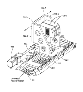
[0072] 2.3 Moving Support for Laser-Galvo Marking Head Processing System
[0073] Figures 15 and 16 illustrate a pellet-shaped article conveyer with
one or
more laser/galvo marking head units 700 mounted to a moveable support, e.g., a
gantry
702. In this embodiment, two marking head units 700 are provided, although the
support or gantry 702 could also support only a single head unit, or more than
two head
units. Gantry 702 includes a base 702.1 having an aperture 702.2 through which
the
articles are visible. One or more support walls 702.3 extend from the base
702.1, and a
bridging wall 702.4 extends between support walls and supports the head units.
13
CA 02672587 2009-06-12
WO 2008/076341 PCT/US2007/025570
[0074] The conveyer is in the form of an endless loop (115, Figure 3)
that
includes a plurality of carrier bars (120, Figure 4) each having a plurality
of recesses
(125, Figure 3). Each laser/galvo marking head unit is dedicated to process a
unique
area of the conveyer that contains multiple pellet-shaped articles positioned
within
rows of recesses across a set of carrier bars 701. The unique areas of the
head units
may be separate, or at least partially overlap. As stated earlier, the speed
for laser
drilling and laser printing / etching applications can be significantly higher
than the rate
at which the pellet-shaped articles can be handled. This is true for most
cases,
however, the time required for laser printing or etching complex images and
logos can
limit the rate at which the pellet-shaped articles can be conveyed past the
laser/galvo
system. To maximize the throughput of the system, the conveyer should
preferably
feed the pellet-shaped articles at the optimum product handling speed,
regardless of the
complexity of the desired laser printed image or logo.
100751 To laser a complex logo, one or more laser/galvo marking head
units
700, preferably 2 or more, are mounted above or adjacent the conveyer to the
gantry
702, which runs parallel to the conveyer feed direction, e.g., using a set of
linear
bearing rails 703 provided on each side of the carrier bars 701. Bearing rails
703
cooperate with grooves 707 provided to the base 702.1. The linear,
reciprocating
motion of the gantry 702 is controlled independently of the conveyer by using
a servo
motor 705 and ball screw 704 drive system. The motion of the gantry can also
be
controlled using other type of equivalent drive systems used in the art such
as linear
belt drives. The movable support can take other forms, such as an endless belt
which
supports the laser units adjacent the conveyer. Other forms of non-
reciprocating
movable support are also possible.
[0076] The gantry servo motor 705 has an encoder to precisely position
and
speed synchronize the gantry relative to the pellet-shaped article conveyer
drive
system. As the conveyer feeds the pellet-shaped articles along or past the
laser
processing area, the gantry 702 begins at a stationary starting position. The
motion
controller commands the gantry servo motor 705 to rotate the ball screw 704,
and
hence drive the gantry in the same forward direction as the conveyer feed
until the
gantry forward movement speed is synchronized with the conveyer article
transport
14
CA 02672587 2009-06-12
WO 2008/076341 PCT/US2007/025570
speed. This creates a system where there is no relative motion between the
laser/galvo
marking heads and the pellet-shaped articles to be processed. Synchronization
can also
be achieved by temporarily locking (e.g., magnetically and/or mechanically)
the
movable support relative to the conveyer, and then unlocking them when forward
motion is complete. This may involve providing the head units on a movable or
telescoping structure to move towards and away from the conveyer.
[0077] The laser/galvo marking heads 700 begin processing their dedicated
area (which may include the articles in one or more carrier bars as shown in
Fig. 16) of
the conveyer that contains multiple pellet-shaped articles positioned within
rows of
recesses across a set of carrier bars 701. When the system has completed the
laser
drilling, printing or etching of the articles, the gantry's forward movement
is stopped
and the servo motor 705 reverses the direction of the ball screw 704 to return
the
gantry 702 to the starting position. The gantry then remains stationary until
the next set
of pellet-shaped articles is conveyed into position, at which time the process
is
repeated.
[0078] In one embodiment, the pellet-shaped articles may have multiple
layers
beneath the coating layer, with each layer displaying or revealing a different
color
depending on the laser depth and/or power, etc., of the laser beam For
example, the
pellet-shaped articles may have a cross-sectional configuration including a
coating
layer 250, a first color layer 255, a second color layer 260 and a medicine
layer 265, as
shown in Fig. 6. The first layer 255 will display a first color (or
characteristic, e.g.,
texture) if lasered to that depth by the first laser unit, while the second
layer 260 will
display a second color if lasered to that depth by the second laser unit. In
addition, the
coating layer 250 and the medicine layer 265 can have different color
appearances.
This can be used for the production of pellet-shaped articles having a
composite image
including multiple colors.
[0079] Alternatively, multiple color pellet-shaped articles can be
created using
the same laser unit, e.g., by altering the depth and/or power of the single
laser unit on
different portions of the same pellet-shaped articles. The laser beam focal
length of a
single 3-Axis laser unit can be adjusted to etch to multiple depths, removing
various
layers of coating to reveal multiple colors.
=
CA 02672587 2014-08-05
[0080] 2.4 Ramp Feed With Two-Sided Processing
[0081] Fig. 7 is a schematic view of a system including a ramp-feed
conveyer
275 as described in relation to Fig. 3, including a laser unit 280 with a
laser 285 and
galvo 290, inspection units 295, 300, an accept bin 305 and a reject bin 310.
Further
system 220 includes a transfer unit 315, e.g., a top pick-up unit, to expose
the opposite
side of the pellet-shaped articles that has not been processed upstream. This
top pickup
unit is similar to that disclosed in relation to U.S. Patent No. 5,878,658.
The top pick-up
unit exposes the second side of the articles to a second laser unit 320,
including a laser
325 and a galvo.
[0082] 3.0 System Controller with Multi-Axis Motion Controller
[0083] Fig. 8 illustrates a schematic view of a control system 400
according to an
embodiment of the present invention. The control system 400 includes a
controller 405
that is provided with one or more input signals 406, 410, e.g., from each
inspection unit
415 and a system encoder feedback 420 that monitors the rotational position of
the
motors, from which the position of the recesses in the feed processing drum or
the carrier
bars can be determined. Based on the input signals, controller 405 provides
control
signals to each laser unit 425, the ejection unit 430 and the system motors
435.
[0084] Each inspection unit 415 could be in the form of one or more simple
photoelectric sensors or a more complicated a multi-camera PC based vision
system. The
inspection unit provides feedback to the controller based on the inspection
data. This
could be to provide information in regard to an upcoming operation. This could
also be to
verify that a previous operation occurred successfully and the pellet-shaped
articles are
acceptable to discharge.
[0085] The system encoder feedback 420 is provided to control the servo
motors
to accurately position the product for processing, e.g., laser drilling and/or
printing/etching. The encoder feedback is used for accurate tracking of the
tablets
between successive operations. The encoder information is also used for the
ejection unit
430 to discharge the good products.
[0086] The system motors 435 are used to drive the drums and/or carrier
bars for
feeding the product and conveying the product through various operations.
16
CA 02672587 2009-06-12
WO 2008/076341
PCT/US2007/025570
[0087] Each galvo of the laser unit is used to aim the laser beam to
create a
specific pattern for laser drilling, printing or etching. The laser/galvo
controller is
designed to receive encoder position information from the system controller
405. This
allows the galvo to control the output coordinates of the laser beam to laser
drill, print
or etch product while it is moving. This helps to increase throughput. The
galvo
controller provides a trigger signal to fire the laser as well. The laser
system provides
the optical beam power for laser drilling, printing or etching.
[0088] The galvanometer uses an encoder for feedback on the target
position.
Once the galvo starts firing the laser in a pattern of holes, the encoder
feedback is used
to move the beams directing the laser so that the beams stay focused properly
on the
pellet-shaped article, e.g., tablet, caplet or capsule. The galvo controller
provides a
trigger signal to the laser. This is efficient because the galvo can fire the
laser
immediately after the mirrors are in position to do so. This also improves the
efficiency of the machine and the throughput of the system per laser.
[0089] Controller 405 can be used with any of the embodiments described
above, it can take the form of a general purpose computer, or it may be a
dedicated
laser/galvo controller specifically designed for the laser marking head unit,
as in the
controller for the Keyence units specified earlier.
[0090] 4.0 Laser Drill Hole Drilling Operations
[0091] Figs. 9-13 schematically illustrate options for drilling holes
using the
laser unit described above. A typical laser drilling system uses either a mask
or a fine
focus head to adjust the size of the single laser hole. The laser may be
pulsed multiple
times to create the proper depth of the hole.
[0092] As described in relation to U.S. Application Publication no. US-
2004-
0094050-Al, one example of an article A is shown by Figure 9. Article A may be
round, although the article could be a caplet as well. The article A has a
depth,
diameter and shape which may vary. The article A is provided with a laser hole
500,
which is shown on an enlarged scale in Figure 10. The diameter of the hole 500
is
designed to be greater than about 800 micrometers or greater, e.g., between
minimum
and maximum values, such as abouf3mm-6mm, or about 5-10 times the size of the
hole diameter in prior art systems. The depth of the hole is typically in the
range of
17
CA 02672587 2009-06-12
WO 2008/076341
PCT/US2007/025570
about 450-500 micrometers. The depth of the hole is at least equal to and
preferably
greater than the thickness of the coating to achieve the desired effect. The
depth is
controlled by pulsing the laser at least one time, and preferably multiple
times in the
same position until the depth is proper.
[0093] In a first mode (Fig. 11), the diameter of the holes is controlled
by using
the laser to create holes having a diameter in the range of 400-800
micrometers.
However, in a second mode, the laser according to one embodiment is controlled
by
creating a series of holes in a predetermined pattern, as shown in FIGS. 12
and 13. In
FIGS. 12 and 13, a large diameter hole, e.g., greater than 800 micrometers,
preferably
about 3-6mm, is created by pulsing the laser with smaller diameter holes 505
in
different positions to create the large diameter hole. In FIG. 12, the pattern
includes
seven holes in the general shape of a hexagon, while FIG. 13 shows the pattern
to
include many more smaller holes, e.g., 37 holes with 4 on each side of a
generally
hexagonal shaped hole. In general the number and size of the holes and the
pattern size
and shape may vary to create the desired hole diameter. Changing the hole
diameter
and/or depth affects the surface area of the article exposed to the fluids in
the digestive
tract, which may be used to better control the release of the medicine. In
other words,
one inventive concept extends to increasing the surface area exposed to the
fluid in the
stomach, regardless of how the increased surface area is achieved. The
increased
surface area may me uniform or non-uniform cross section. Increased surface
area may
be achieved via larger drilled holes, or by etching away a portion of the
coating using
the laser, for example.
[0094] The galvo has two mirrors mounted to high performance servo motors
for controlling the x and y coordinates of the laser beam, and may contain a Z-
axis
scanner to adjust the focal length (z coordinates) of the laser beam. The
laser
coordinates are controlled by the mirror positions. The laser/galvo controller
determines the mirror and laser focal length positions.
[0095] In one aspect of the invention the galvo is commanded to point the
laser
at the center of the tablet and then the controller fires the laser for a set
period of time.
This period of time combined with the laser pulse width and pulse period will
determine the hole depth. For example, each product may be in the vicinity of
the laser
18
CA 02672587 2009-06-12
WO 2008/076341
PCT/US2007/025570
for a total time of about 50-300 milliseconds (ms), preferably about 100-200
ms, and
most preferably 150 ms, depending on the product involved. In that time, the
pulse
period may be about 400-600 microseconds, e.g., about 500 microseconds, in
which
the product can be lasered. The pulse width may be about 40-60 microseconds,
e.g.,
about 50 microseconds. In that pulse width, the product may be pulsed 7-8
times to
create the proper depth, although the correct depth may be achieved with a
single pulse,
or more than 7-8 pulses.
[0096] In another aspect of the invention, the galvo will be commanded to
perform a complex series of moves, while at the same time electronically
gearing to the
conveyer. The controller will command the laser to fire at the appropriate
times. The
depth of the hole is determined be laser pulse width, pulse period and galvo
speed. The
diameter of the hole is determined by the software in the controller 400.
[0097] In another aspect of the invention, the laser/galvo controller can
vary the
spot size of the laser beam to create larger diameter and/or deeper holes in
the product.
[0098] One advantage of these systems is that the same laser can be used
to
create holes having a diameter in the range of approximately 400 micrometers
to 6
millimeters. This avoids the need to switch lasers or to buy lasers with a
large
diameter, which can be expensive.
[0099] The laser can also be used to rapidly drill holes on a plurality
of rows of
articles across a wide processing area, e.g., 1 or more carrier bars, such as
2-5 carrier
bars. The range of motion for the galvo is such that it is able to point at
multiple
products across the conveyer bed. For example, the laser can be fired at 6
discrete
products with 5/8" spacing between the products. The galvo can be commanded to
point at each product in sequence and then fire the laser at each.
[00100] Laser Print Example
[00101] Fig. 14 schematically illustrates a pellet-shaped articles 600 in
the form
of a round or lentil shaped product, that is subjected to laser printing
according to an
embodiment of the present invention. In this example, article 600 includes a
company
brand, "Ackley". The brand is enlarged in Fig. 14, adjacent the article 600,
to better
demonstrate the lasering.
19
CA 02672587 2014-08-05
[00102] A typical laser printing system uses a mask to create the printed
logo on
the product. Only a single product can be laser printed at a time. Changing
the logo
requires changing the mask.
[00103] The laser printing system according to an embodiment of the present
invention utilizes a pattern of small shallow circular incisions (holes) 605
on the surface
of, through or partly through the top layer of coating to engrave the printed
logo. A
continuous wave or high laser pulse frequency is used; therefore adjacent
holes are at
least partially overlapping. As mentioned earlier, the power (e.g., 30W or
less) of the
laser for printing and etching may be significantly less than the power (e.g.,
30W or
more) required for laser drilled holes (e.g., for time-release purposes).
There are again an
infinite number of logos that can be printed. The pattern is programmable so
no change-
over of a mask is required.
[00104] The printed logo can include alpha-numeric characters, logos, or
other
images. The printed logo could even be some type of machine readable code like
a UPC
or 2D Data Matrix code. For example, as shown in Figure 14, one or more of the
laser
holes in the logo name could include a machine readable code 605.1. The
machine
readable code could also include one or more of the codes as described in PCT
application no. PCT/US2005/020860. The code could be configured to include a
Lot
Code, Date Code or other batch related information.
[00105] The printed logo could also include a serial number which would be
incremented automatically during the production run to serialize the product
being
printed.
[00106] While the invention has been described in connection with what are
presently considered to be the most practical and preferred embodiments, it is
to be
understood that the invention is not to be limited to the disclosed
embodiments, but on
the contrary, is intended to cover various modifications and equivalent
arrangements
included within the scope of the invention. Also, the various embodiments
described
above may be implemented in conjunction with other embodiments, e.g.,
= CA 02672587 2014-08-05
aspects of one embodiment may be combined with aspects of another embodiment
to
realize yet other embodiments.
=
20a