Note: Descriptions are shown in the official language in which they were submitted.
CA 02672600 2009-06-12
WO 2008/076354 PCT/US2007/025597
SIGNAL-PROCESSING SYSTEMS AND METHODS FOR RFID-TAG SIGNALS
BACKGROUND OF THE INVENTION
Field of the Invention
[0001] The present invention relates generally to radio-frequency
identification (RFID)
systems, and in particular relates to systems for and methods of processing
RFID-tag signals
that improve the readability of such signals by a RFID-tag reader.
Technical Background
[0002] Radio-frequency identification (RFID) is a remote recognition technique
that
utilizes RFID tags having information stored therein. The stored information
is retrievable
via radio-frequency (RF) communication between the RFID tag and a RFID-tag
reader. The
typical RFID system utilizes a RFID-tag reader, which is often designed to be
hand held for
the sake of mobility. When the RFID-tag reader is brought sufficiently close
to a RFID tag, it
can read a digital RFID-tag signal communicated by the tag. RFID systems are
conventionally used for inventory management and product tracking in a variety
of different
industries, as well as in libraries and hospitals. The data encoded into a
RFID tag can
generally be written at a distance, and some types of RFID tags can be re-
written multiple
times.
[0003] There are three main types of RFID tags. The first type is a passive
RFID tag that
has a microcircuit (typically, a digital memory chip) with no internal power
supply. The
microcircuit includes or is coupled to an antenna. A passive RFID tag is
powered by an
incoming RF interrogation signal from the RFID-tag reader. The RF
interrogation signal
provides enough power for the microcircuit to communicate the information
stored in the
RFID tag to the RFID-tag reader via an electromagnetic RF tag signal from the
RFID tag
antenna.
[0004] The second type of RFID tag is semi-passive, and includes a microchip,
antenna,
and a small power supply that powers the microchip, allowing the RFID tag to
operate and
communicate a RFID tag signal without requiring power from the incoming RF
signal,
leading to a greater read range.
1
CA 02672600 2009-06-12
WO 2008/076354 PCT/US2007/025597
[0005] The third type of RFID tag is active and has its own power supply.
Active RFID
tags generate an outgoing RF tag signal and can respond to RF interrogations
from the RF tag
reader, or periodically generate their own outgoing RF tag signal.
[0006] In reading RFID tags, the RFID-tag reader interrogates the tag many
times (e.g.,
more than 100 times) per second. The RFID-tag reader reads a corresponding
RFID-tag signal
for each interrogation. If the acquired RFID-tag signal does not correspond to
a legitimate
digital stream of a standardized protocol and error-checking method, then the
acquired RFID-
tag signal is identified as a "read error" and discarded. In practice, ambient
electronic noise
from a variety of sources (typically, machines and devices near the RFID tag
or electronic
noise in the RF circuitry of the reader) limits the range of the RFID-tag
reader and causes
many of the RFID interrogations to generate read errors. Other RFID-tag signal
impairments
can also occur, such as multi-path fading and bandwidth reduction and
dispersion, which
result in less-sharp rise and fall times. Consequently, only some of the RFID-
tag signals are
properly read, and the ability to properly read the RFID tag signals decreases
with the distance
between the RFID tag and the RFID-tag reader.
[0007] Improving the RFID reading capability of a RFID system can allow for a
greater
read range, smaller antenna sizes for the RFID tag, better RFID capability in
electronically
noisy environments, higher success rate of reading the RFID tag, etc.-all of
which improve
the RFID system efficiency while reducing system cost and user frustration.
SUMMARY OF THE INVENTION
[0008] One aspect of the invention is a method of reading an analog RFID-tag
signal
communicated from a RFID tag, wherein the analog RFID-tag sigrial comprises an
original
sequence of bits. The method includes receiving multiple copies of the analog
RFID-tag
signal, wherein at least some of the received multiple copies differ from each
other due to, for
example, noise or other signal impairments. The method also includes
converting the
received multiple copies of the analog RFID-tag signals to corresponding
multiple received
digitized RFID-tag signal representations each comprising a plurality of
digital samples. The
method further includes processing the multiple received digitized RFID-tag
signal
representations on a sample-by-sample basis to obtain a recovered digital RFID-
tag signal
representative of the original sequence of bits.
2
CA 02672600 2009-06-12
WO 2008/076354 PCT/US2007/025597
[0009] Another aspect of the invention is a RFID reader apparatus for reading
an analog
RFID signal communicated by a RFID tag, wherein the analog RFID signal
comprises a
sequence of bits. The apparatus includes an antenna adapted to receive analog
RFID signals
communicated by the RFID tag and to emit RFID tag interrogation signals that
cause the
RFID tag to communicate multiple copies of the analog RFID signal. The
apparatus also
includes a demodulator operably coupled to the antenna and adapted to
demodulate the
received analog RFID signals. The apparatus further includes an analog-to-
digital (A/D)
converter operably coupled to the demodulator and adapted to convert each
demodulated
analog RFID signal to a corresponding digitized RFID signal representation
comprising a
plurality of digital samples. The apparatus also includes a central processing
unit (CPU)
operably coupled to the demodulator. The CPU is adapted to process, on a
sample-by-sample
basis, multiple digitized RFID signal representations to recover a digital
RFID signal
representative of the sequence of bits.
[0010] Another aspect of the invention is a method of reading a RFID-tag
signal
communicated by a RFID tag and having an original sequence of bits. The method
includes
receiving multiple copies of the RFID-tag signal using a RFID-tag reader,
wherein at least
some of the received multiple copies differ from one another. The method also
includes
digitizing the received multiple copies to form digitized RFID-tag signal
representations each
comprising digitized samples. The method further includes processing the
digitized RFID-tag
signal representations to obtain a recovered digitized RFID-tag signal that
yields the original
sequence of bits.
[0011] Additional features and advantages of the invention will be set forth
in the
following detailed description, and in part will be readily apparent to those
skilled in the art
from that description or recognized by practicing the invention as described
herein, including
the following detailed description, the claims, as well as the appended
drawings.
[0012] It is to be understood that both the foregoing general description and
the following
detailed description present embodiments of the invention, and are intended to
provide an
overview or framework for understanding the nature and character of the
invention as it is
claimed. The accompanying drawings are included to provide a further
understanding of the
invention, and are incorporated into and constitute a part of this
specification. The drawings
illustrate various embodiments of the invention and together with the
description serve to
explain the principles and operations of the invention.
3
CA 02672600 2009-06-12
WO 2008/076354 PCT/US2007/025597
BRIEF DESCRIPTION OF THE DRAWINGS
[0013] FIG. 1 is a schematic diagram of an example embodiment of a RFID system
according to the present invention having a signal-processing circuit adapted
to carry out the
signal-processing method of the RFID-tag signals according to the present
invention;
[0014] FIG. 2 is a schematic diagram of an example embodiment of a signal -
processing
circuit for the RFID-tag reader of FIG. 1;
[0015] FIG. 3A is a simulated time plot of an example digital RFID-tag signal
(STo) as
generated by the microcircuit in the RFID tag and having an example bit
sequence of
I1001010;
[0016] FIG. 3B is a simulated time plot of ten received digitized RFID-tag
signals STR
based on the example digitized RFID-tag signal STo of FIG. 3A as received by
the RFID-tag
reader;
[0017] FIG. 3C plots the sample-by-sample average of the ten digital RFID-tag
signals
STR of FIG. 3B;
[0018] FIG. 4 is a simulated time plot of the sample-by-sample average <STR>
of
received digitized RFID-tag signal representations STR for different numbers
of received
digital RFID-tag signal representations, showing the percentage of errored
bits for the
received digital RFID-tag signal representations, illustrating how averaging
an increasing
number of received digital RFID-tag signal representations on a sample-by-
sample basis
increasingly reduces the percentage of errored bits; and
[0019] FIG. 5 is a flow diagram of an example algorithm describing an example
of the
RFID-tag reading method of the present invention wherein the sample-by-sample
signal
processing includes averaging the digitized RFID-tag signal representations.
DETAILED DESCRIPTION OF THE PREFERRED EMBODIMENTS
[0020] Reference will now be made in detail to the present preferred
embodiments of the
invention, examples of which is/are illustrated in the accompanying drawings.
Whenever
possible, the same reference numbers or letters are used throughout the
drawings to refer to
the same or like parts. In the description below, only those elements
necessary for
understanding and implementing the invention are shown.
[0021] FIG. 1 is a schematic diagram of an example embodiment of a RFID system
10
according to the present invention as adapted to carry out the RFID-tag signal
signal-
4
CA 02672600 2009-06-12
WO 2008/076354 PCT/US2007/025597
processing method according to the present invention. RFID system 10 includes
a RFID tag
20 that includes a microcircuit 22 electrically coupled to an antenna 26.
Microcircuit 22 is
adapted to store digital information and generate a digital signal comprising
a sequence of bits
representative of the stored information.
[0022] RFID system 10 also includes a RFID-tag reader 30 that includes a
signal-
processing circuit 32 electrically coupled to a transmit/receive antenna
system ("antenna") 36.
Note that antenna 36 could include separate transmit and receive antennas
rather than a single
transmit/receive antenna. The single-antenna embodiment is described below for
the sake of
illustration.
[0023] In an example embodiment, RFID-tag reader 30 is operably coupled (e.g.,
via an
electrical line, optical fiber, wireless connection, etc.) to an external
database DB that stores
the RFID-tag information as read by the RFID-tag reader.
[0024] FIG. 2 is a schematic diagram of an example embodiment of signal-
processing
circuit 32 of RFID-tag reader 30. Circuit 32 includes a three-port signal -
directing element 50
electrically coupled to antenna 36. Three-port signal-directing element 50 has
a
transmit/receive port 52TR, a receiving-side port 52R and a transmitting-side
port 52T.
Signal-processing circuit 32 includes a receiving amplifier 58R electrically
coupled to
receiving-side port 52R, a receiving demodulator 62R electrically coupled to
the receiving
amplifier, a receiving analog-to-digital (A/D) converter 66R electrically
coupled to the
receiving demodulator, and a receiving digital signal processor 68R
electrically coupled to the
receiving A/D converter.
[0025] Circuit 32 also has a microprocessor 76 electrically coupled to
receiving digital
signal processor 68R. Microprocessor 76 is adapted (e.g., programmed) to
control the overall
operation of signal-processing circuit 32, including signal transmission and
reception (as
discussed below), and performing logic and computing operations on processed
signals,
including carrying out the RFID-tag signal signal-processing methods described
below.
[0026] Antenna 36, three-port signal-directing element 50, receiving amplifier
58R,
receiving demodulator 62R, receiving A/D converter 66R, receiving digital
signal processor
68R and microprocessor 76 constitute an example embodiment of a RF receiver
32R.
[0027] Signal -processing circuit 32 also includes a transmitting amplifier
58T electrically
coupled to transmitting-side port 52T, a transmitting modulator 62T
electrically coupled to
the transmitting amplifier, a transmitting digital-to-analog (D/A) converter
66T electrically
CA 02672600 2009-06-12
WO 2008/076354 PCT/US2007/025597
coupled to the modulator, and a transmitting digital signal processor 68T
electrically coupled
to the transmitting D/A converter and to microprocessor 76.
[0028] Antenna 36, three-port signal -directing element 50, transmitting
amplifier 58T,
transmitting modulator 62T, transmitting D/A converter 66T, transmitting
digital signal
processor 68T and microprocessor 76 constitute an example embodiment of a RF
transmitter
32T. Thus, in an example embodiment, signal-processing circuit 32 comprises an
RF
transmitter 32T and a RF receiver 32R that have some common elements, namely
antenna 36,
signal-directing element 50, and microprocessor 76.
[0029] In an example embodiment, receiving digital signal processor 68R,
transmitting
digital signal processor 68T and microprocessor 76 constitute a central
processing unit (CPU)
78. In an example embodiment, this CPU is formed from a field-progranunable
gate array
(FPGA), and in another example embodiment is formed from an integrated circuit
designed
specifically for the particular purpose of the present invention (i.e., an
application-specific
integrated circuit or ASIC).
[0030] Signal-processing circuit 32 also includes a memory unit 80
electrically coupled to
microprocessor 76, and a display unit 84 electrically coupled to the
microprocessor. Memory
unit 80 is adapted to store information, such as RFID-tag reader settings and
status, and
processed data such as raw and/or processed RFID-tag signals, as described
below. Memory
unit 80 also serves as a computer-readable medium for storing computer-
executable
instructions for carrying out the methods of the present invention either via
the operation of
microprocessor 76 or via the operation CPU 78 as a whole, as described below.
In an
example embodiment, memory unit 80 is included in CPU 78.
Method of operation
[0031] In an example embodiment of the operation of RFID system 10, RFID-tag
reader 30
transmits an interrogation signal SI" to RFID tag 20, as illustrated in FIG.
1. This is
accomplished using RF transmitter 32T of signal-processing circuit 32, as
shown in FIG. 2.
In particular, microprocessor 76 directs transmitting signal processor 68T to
generate a digital
signal having an interrogation bit stream. This digital signal is converted to
an analog signal
via D/A converter 66T. This analog signal is then modulated onto a RF carrier
by
transmitting modulator 62T to form analog interrogation signal SI'. Analog
interrogation
signal SI' is then amplified by transmitting amplifier 58T and enters signal-
directing element
6
CA 02672600 2009-06-12
WO 2008/076354 PCT/US2007/025597
50 at transmitting port 52T. The amplified analog interrogation signal SI' is
then directed
out of transmitting/receiving port 52TR to antenna 36, which converts signal
SI' into an
electromagnetic interrogation signal SI" (FIG. 1).
[0032] Electromagnetic interrogation signal SI" is received by RFID tag
antenna 26, which
converts this signal back into analog interrogation signal SI'. RFID tag
microcircuit 22
receives analog interrogation signal SI', converts it to digital interrogation
signal SI, and
processes this signal to assess whether it has the proper interrogation bit
stream. If necessary,
microcircuit 22 uses the energy in the interrogation signal to power itself.
[0033] If the proper interrogation bit stream is identified by microcircuit
22, then the
microcircuit generates an "original" digital RFID-tag signal STo having a bit
sequence that
represents information stored in the microcircuit memory (not shown).
Microcircuit 22
includes an A/D converter and other electronic circuitry (not shown) that
converts original
digital RFID-tag signal STo to an analog signal that is used to modulate the
incoming RF
carrier to form analog RFID-tag signal ST'o. Analog RFID-tag signal ST'o is
then
communicated by RFID tag antenna 26 as an electromagnetic RFID-tag signal ST"o
representative of the original bit sequence in the digital RFID-tag signal
STo.
[0034] Electromagnetic RFID-tag signal ST"o is received by RFID-tag reader 30.
Specifically, signal ST"o is received and processed by RF receiver 32R. RFID-
tag reader
antenna 36 converts signal ST"o into a received analog RFID-tag signal ST'R.
Analog
RFID-tag signal ST'R typically is not the same as the original electrical
analog RFID-tag
signal ST'o due to any one of a number of factors, such as ambient electronic
noise,
attenuation due to an intervening object or medium, multi-path propagation
effects, or the
read distance being at or over its normal limit.
[0035] RFID-tag signal ST'R travels from antenna 36 to signal -directing
element 50, which
directs the signal out of receiver-side port 52R to receiving amplifier 58R,
which amplifies
this signal. The amplified signal ST'R then proceeds to receiving demodulator
62R, which
demodulates the signal to recover the base analog signal, which might be
further impaired by
thermal and circuit noise of signal-processing circuit 32. The impaired base
analog signal
then proceeds to receiving A/D converter 66R, which converts this signal into
a received
digitized RFID-tag signal representation STR comprising a plurality of digital
samples. The
digitized signal may be highly oversampled and the quantization of the samples
may have
many levels, causing the digitized signal representation to have many more
bits than the
7
CA 02672600 2009-06-12
WO 2008/076354 PCT/US2007/025597
original digital signal. This digitized signal representation proceeds to
receiving digital signal
processor 68R for signal processing. Here, the term "signal processing"
optionally includes
signal conditioning, as described below, in addition to digital signal
processing of the
digitized signals.
[0036] The RFID tag reading method of the present invention includes carrying
out the
above-described RFID-tag interrogation process multiple times, thereby causing
RFID tag 20
to communicate multiple copies of the original RFID-tag signal ST"o. The RFID-
tag reader
30 may send a single interrogation signal or multiple interrogation signals to
the RFID tag 20
to cause the RFID tag to communicate multiple copies of the original RFID-tag
signal ST"o.
RFID-tag reader 30 then reads (i.e., receives and processes) each communicated
RFID-tag
signal as described above, wherein at least some of the received digitized
RFID-tag signal
representations STR differ from each other, e.g., due to noise or other
impairments. Thus,
receiving digital signal processor 68R is adapted to process multiple
digitized RFID-tag
signal representations STR.
[0037] FIG. 3A is a simulated time plot of an example of the original digital
RFID-tag
signal STo as generated by microcircuit 22 of RFID tag 20. Signal STo
comprises the
sequence of bits 11001010. FIG. 3B is a time plot of ten digitized RFID-tag
signal
representations STR of FIG. 3A as read by RFID-tag reader 30. Note that the
ten digitized
RFID-tag signal representations STR ( STR(1), STR(2), ...STR(n), wherein n =
10) differ
from each other according to a noise impairment in this example, and that no
one signal could
be used to recover the original bit sequence of the original RFID-tag signal
STo shown in
FIG. 3A. Other impairments could occur as well, and the particular example of
FIG. 3A is
used by way of illustration.
[0038] In order to recover the original bit sequence in original digital RFID-
tag signal STo,
in an example embodiment receiving digital signal processor 68R processes the
different
digitized RFID-tag signal representations STR(1), STR(2), ...STR(n) on a
sample-by-sample
basis to obtain a recovered digitized RFID-tag signal representation that
closely matches the
original digital RFID-tag signal STo and the bit sequence therein.
[0039] The recovered bit sequence is then provided to microprocessor 76 for
further
processing, e.g., for storage in memory unit 80 via a memory signal SM, to
display on display
84 via a display signal SD, or transmission to external database DB via an
external database
signal SDB (FIG. 1).
8
CA 02672600 2009-06-12
WO 2008/076354 PCT/US2007/025597
[0040] Digital-signal processor 68R is adapted to process the different
digitized RFID-tag
signal representations STR(1), STR(2), ...STR(n) on a sample-by-sample basis.
One example
embodiment of this sample-by-sample processing involves sample-by-sample
averaging.
FIG. 3C illustrates the simulated result of a sample-by-sample averaging
process as carried
out by receiving digital signal processor 68R for the ten different versions
of the received
digitized RFID-tag signal representations STR of FIG. 3B. The average received
digitized
RFID-tag signal representation <STR> provides a slightly noisy but otherwise
accurate
representation of its original counterpart STo and the sequence of bits
therein as generated by
RFID tag 20. This example illustrates the power of sample-by-sample signal
averaging to
reduce noise impairments.
[0041] In an example embodiment, the different versions of the received
digitized RFID-
tag signal representations STR are stored in memory unit 80 and are then
sample-by-sample
processed by microprocessor 76 or receiving digital signal processor 68R. In
another
example embodiment, the sample-by-sample processing occurs in real-time in
receiving
digital signal processor 68R as each digitized RFID-tag signal representation
is received. In
an example embodiment, the sample-by-sample processing stops when a suitable
degree of
convergence on the final form of the digitized RFID-tag signal representation
is achieved, or
when the recovered digital signal has the proper cyclic redundancy check
value.
[0042] In an example embodiment wherein the signal processing includes sample-
by-
sample averaging, the averaging process starts off with averaging two received
digitized
RFID-tag signal representations STR and averaging an increasing number, of
such signal
representations until the calculated average RFID-tag signal representation
<STR> does not
change significantly as a function of the number of averaged signal
representatioiis. The
measure of the degree of convergence can be performed in a number of different
ways, such
as on a sample-by-sample basis, by performing a correlation between different
averaged
signal representations, etc. More generally, an example embodiment of the
invention
involves sample-by-sample processing of an increasing number of digitized RFID-
tag signal
representations STR until the recovered digitized RFID-tag signal remains
substantially
constant.
[0043] FIG. 4 is a simulated time plot of the average received RFID-tag signal
representation <STR> as calculated using different numbers of received signal
representations
STR. The plot shows the percentage of errored bits on the right-hand axis. As
the plot
9
CA 02672600 2009-06-12
WO 2008/076354 PCT/US2007/025597
indicates, a single received RFID-tag signal representation STR has 31 %
errored bits.
Averaging two received RFID-tag signal representations STR reduces the errored
bits to 17%,
and averaging five received RFID-tag signal representations STR reduces the
errored bits to
6%. After averaging ten received signal representations STR, the errored bits
is reduced to
0.2%, and averaging twenty or more received RFID-tag signal representations
STR reduces
the errored bits to 0%. Note also that the average received RFID-tag signal
representation
<STR> remains substantially unchanged from averaging ten received signal
representations
STR versus averaging twenty such signal representations. The simulation
indicates that for
this example, sample-by-sample averaging of ten or so received RFID-tag signal
representations STR provides adequate resolution to recover the original bit
sequence in
original digital RFID-tag signal representation STo and thus to successfully
read the RFID
tag. This also supports the above-described example method of the invention
that includes.
averaging of multiple received signal representations using an increasing
number of received
signal representations until the average received RFID-tag signal
representation remains
substantially constant, or until the recovered digital signal has the proper
cyclic redundancy
check value.
[0044] Since original RFID-tag signals STo can be generated and communicated
rapidly
by RFID tag 22 (e.g., in a few milliseconds for ten transmissions), and
because the digital
signal processing method in RFID-tag reader 30 can be carried out equally fast
by signal-
processing circuit 32, there is no substantial delay in reading the RFID tag
using the systems
and methods of the present invention.
Other applicable signal-processing techniques
[0045] In addition to the above-described example sample-by-sample signal-
processing
technique of the digitized RFID-tag signal representations STR, there are a
number of other
signal processing techniques and variations applicable to the present
invention. These are
now discussed below. For the purposes of the present invention, "signal
conditioning"
generally describes signal-processing techniques other than sample-by-sample
signal
processing.
CA 02672600 2009-06-12
WO 2008/076354 PCT/US2007/025597
[0046] In order to efficiently process multiple digitized RFID-tag signal
representations
STR, it is useful to ensure that they are synchronized. Thus, in an example
embodiment of the
present invention, signal-processing circuit 32 is adapted to synchronize the
multiple received
RFID-tag signal representations STR using, for example, clock recovery
techniques. In an
example embodiment of this approach, a synchronization bit pattern is provided
to the RFID-
tag bit sequence in the original RFID-tag signal STo to facilitate this
synchronization.
[0047] In another example embodiment of the present invention, signal-
processing
circuit 32 is adapted to shift individual received signal representations STR
back and forth in
time to maximize correlation with other received signal representations from
the same RFID
tag. This serves to ensure that the different samples are "lined up," thereby
making the
sample-by-sample averaging process more efficient.
[0048] In another example embodiment of the present invention, signal-
processing circuit
32 is adapted to perform a number of digital sampling techniques. One such
technique is
called "oversampling," which involves taking many digital samples per bit of
the analog
RFID-tag signal ST'R-that is, more samples than are required by the sampling
theorem to
recover the sampled signal. In combination with the process of quantization
(including using
two or more digital levels per sample), a high-resolution digitized RFID-tag
signal
representation STR of the received analog RFID-tag signal ST'R is obtained.
Using this
technique, the number of bits used to form the digitized RFID-tag signal
representation STR
is greater than (and is preferably significantly greater than) the number of
bits in the RFID-tag
signal itself. Such sampling and quantization is readily accommodated by
signal-processing
circuit 32, which using present-day integrated circuit technology can operate
with cycle times
many orders of magnitude faster than the bit periods of the RFID-tag signal.
[0049] Other examples of sample-by-sample signal processing include:
correlation
techniques (e.g., averaging the product of two consecutive samples), digital
filtering (or
equivalently, weighted averaging of the samples), averaging the square of the
samples,
threshold detection of each sample followed by averaging the resulting binary
states, and
estimation theory techniques. In an example embodiment, the best sample-by-
sample
processing approach (or combination of approaches) to use is determined
empirically for a
given set of RFID-tag reading conditions. For example, one can start with
simple sample-by-
sample averaging and add other variations (e.g., weighted averaging), etc.,
and/or appropriate
signal-conditioning types of signal processing (as discussed below) until a
satisfactory
recovered digital RFID-tag signal is obtained.
11
CA 02672600 2009-06-12
WO 2008/076354 PCT/US2007/025597
Signal conditioning
[0050] In another example embodiment of the present invention, signal-
processing circuit
32 is adapted to carry out digital signal processing in the form of "signal
conditioning." In an
example embodiment, signal conditioning is performed on one or more of the
digital RFID-
tag signal representations so as to improve the quality of the one or more
received signal
representations before further signal processing. In another example
embodiment, signal
conditioning is applied to the recovered digital RFID-tag signal.
[0051] Signal conditioning techniques are generally used to mitigate errors.
Example
signal conditioning suitable for the present invention include, for example,
smoothing,
filtering (e.g., matched filtering to restore the bandwidth and correct for
rise/fall times, or
Fourier-domain filtering to remove frequency components outside of the known
signal band),
clock recovery, impulse-response deconvolution, and the use of coding
techniques such as
cyclic redundancy coding (CRC), forward error correction (FEC) and the like.
Other signal
conditioning techniques include forming linear (e.g., weighted averaged)
combinations of the
multiple received RFID-tag signal representations, non-linear combinations of
the multiple
received RFID-tag signal representations, and digital filtering wherein
undesired frequency
components are removed or attenuated from the multiple received RFID-tag
signal
representations.
[0052] In an example embodiment, one or more suitable signal-conditioning
techniques are
applied to each digitized RFID-tag signal representation STR prior to
performing sample-by-
sample processing of the signal representations.
[0053] In another example embodiment, one or more suitable signal-conditioning
techniques are applied to the recovered digitized RFID-tag signal. The
aforementioned
coding techniques are best performed on the recovered digitized RFID-tag
signal. Coding
techniques typically involve adding a small number of bits to the communicated
original
digital RFID-tag signal STo. These extra bits allow the recovered digitized
RFID-tag signal
to be checked or improved to ensure that it is the same as or otherwise
suitably represents the
original digital RFID-tag signal.
Example Algorithm
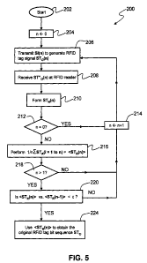
[0054] FIG. 5 is a flow diagram 200 of an example algorithm that includes acts
202
through 224 for carrying out an example of the RFID-tag reading method of the
present
12
CA 02672600 2009-06-12
WO 2008/076354 PCT/US2007/025597
invention, wherein the sample-by-sample signal processing includes simple
averaging for the
sake of illustration.
[0055] The algorithm starts at 202 and immediately proceeds to 204, which
assigns
counting integer n to zero. In 206, RFID-tag reader 30 transmits a (first)
interrogation signal
SI(n) = SI(0), which causes cause RFID tag 20 to communicate a (first)
digitized RFID-tag
signal STo(n) = STo(0).
[0056] In 208, the corresponding electromagnetic RFID-tag signal ST"o(O) is
received by
RFID-tag reader 30. In 210, the RFID-tag reader forms the corresponding
received digitized
RFID-tag signal representation STR(0), which as discussed above is different
from the
original digital RFID-tag signal STo generated by RFID tag 20 due to the
aforementioned
noise effects.
[0057] Query 212 asks whether counter n = 0. Since for the first iteration,
the answer to
this query is "YES," the first received digitized RFID-tag signal STR(0) can
be stored in
memory unit 80. The process then proceeds to 214, which increments counting
integer n
by 1. The process then returns to 206, and 206 through 210 are repeated for n
= 1. This
results in two received digitized RFID-tag signal representations STR(0) and
STR(1), which
can both be stored in memory unit 80 via the operation of microprocessor 76.
[0058] Since the result of query 212 is now n:~ 0, the process moves to 216,
wherein the
two received digitized RFID-tag signals are processed. In an example
embodiment, a sample-
by-sample average of digitized RFID-tag signal representations STR(0) and
STR(1) is
performed. In example embodiments, this average is performed either by
microcircuit 76
operating on the digitized RFID-tag signals stored in memory unit 80, or in
real-time by
signal processor 68R. This provides a first sample-by-sample average digitized
RFID-tag
signal representation <STR(n) > = <STR(1)>.
[0059] Since n = 1, 218 sends the process back to 214, which increments the
counting
integer n by one. The process then returns to 206, where 206 through 216 are
repeated to
form a second average digitized RFID-tag signal representation <STR(n)>
=<STR(2)>,
which is the sample-by-sample average of the three received digitized RFID-tag
signal
representations STR(0), STR(1) and STR(2).
[0060] Since now in 218 n> 1, the algorithm then proceeds to 220, which asks
whether the
differences between the latest average digitized RFID-tag signal
representation <STR(n)> _
<STR(2)> and the previous average digitized RFID-tag signal representation
<STR(n-1)> _
13
CA 02672600 2009-06-12
WO 2008/076354 PCT/US2007/025597
<STR(1)> is less than some threshold value E. In other words, 220 asks whether
the average
digitized RFID-tag signal remains substantially constant as a function of the
increasing
number of received digitized RFID-tag signal representations STR used to form
the average.
Here, the comparison can be performed in any number of ways, such as on a
sample-by-
sample basis, by performing a correlation calculation, or by Fourier-
transforming the two
averages and comparing their frequency-domain counterparts.
[0061] If the answer for 220 is "NO," then the process moves to 214 where the
counting
integer n is incremented by 1. The process then returns to 206, and 206
through 220 are
repeated, wherein in 220 the average digitized RFID-tag signal representations
<STR(3)> and
<STR(2)> are compared. If necessary, 206 through 220 are repeated until a
comparison
between <STR(n)> and <STR(n-1)> satisfies the condition in 220. If the
comparison in 220
does not converge, then the parameter c is reset to avoid an infinite loop.
Once the condition
in 220 is satisfied, then in 224 the average digitized RFID-tag signal
representation <STR(n)>
is used to obtain the original bit sequence in original digital signal STo
generated by RFID
tag 20, and thus obtain the RFID tag information.
[0062] In an example embodiment, signal-processing circuit 32 is adapted
(e.g.,
programmed) to carry out the algorithm of flow diagram 200. In a particular
example
embodiment, the algorithm of flow diagram 200 is embodied in (e.g., programmed
in the
software or firmware of) microprocessor 76 and/or in memory unit 80 so that
the
microprocessor (or CPU 78) can control the operation of signal-processing
circuit 32 to carry
out the RFID-tag reading method of the present invention.
[0063] In an example embodiment the sample-by-sample averaging process and the
comparison of <STR(n)> and <STR(n-1)> in 220 of flow-diagram 200 are carried
out by
receiving digital signal processor 68R and the resulting digitized signal
representation
provided to microprocessor 76 for further processing and/or distribution.
[0064] It will be apparent to those skilled in the art that various
modifications and
variations can be made to the present invention without departing from the
spirit and scope of
the invention. Thus, it is intended that the present invention cover the
modifications and
variations of this invention provided they come within the scope of the
appended claims and
their equivalents.
14