Note: Descriptions are shown in the official language in which they were submitted.
CA 02672788 2009-06-15
1
DESCRIPTION
Induction Heating Appliance For Cooking
Technical Field
[0001] The present invention relates to an induction heating appliance for
induction heating a material to be heated, which utilizes an infrared sensor
for
controlling the temperature of the material to be heated.
Background Art
[0002] The prior art induction heating appliance for cooking is so designed
that an infrared sensor is arranged at a center of a heating coil and an
inverter
circuit is controlled by a controlling means in dependence on an output from
the
infrared sensor to thereby control the output of the heating coil. (See, for
example,
Patent Document 1 listed below.)
[0003] Patent Document: Japanese Laid-open Patent Publication No.
2005-38660
Disclosure of the Invention
Problems to be Solved by the Invention
[0004] It has, however, been found that in the induction heating appliance for
cooking of the structure referred to above, when an article to be heated such
as, for
example, a pot, which is empty (nothing to be cooked is contained in the
article to
be heated), temperature abruptly increases at a portion of the article to be
heated
above that portion of the heating coil winding intermediate between the
outermost
periphery thereof and the innermost periphery thereof, where the density of
magnetic flux developed is highest to emit the maximum heat during the
heating,
and, therefore, it often occurs that as a result of delay in response to
control the
heating output with respect to a high temperature region of the article to be
heated,
CA 02672788 2009-06-15
2
when a thin-walled stainless steel pot of a kind having an inferior thermal
conductivity and a low heat capacity is used as the article to be heated, the
bottom
of the pan tends to be red heated enough to deform by the effect of the
elevated
temperature or a material to be cooked containing a slight quantity of oil or
the like
will be heated to a high temperature.
[0005] If the infrared sensor is arranged so as to detect the temperature of
the article to be heated which is placed at an intermediate portion of the
heating coil,
not the center of the heating coil, or in the vicinity of the inner periphery
of the
winding of the heating coil, the above discussed problems would be resolved.
However, where the infrared sensor is to be provided below the top plate, an
incident window (hereinafter referred to as an infrared incident region),
through
which infrared rays of light from the article to be heated that is placed on
the top
plate, can be incident upon the infrared sensor, the infrared sensor will be
disposed
at a location offset from the center of the heating coil. In such case, the
article to
be heated will not be necessarily placed above the infrared incident region
and, if
the user erroneously places the article to be heated not to obstruct the
infrared
incident region, the infrared sensor will fail to detect the temperature of
the article to
be heated properly. In particular, in the case where the ambiance around the
induction heating appliance for cooking is dark, a problem is often recognized
that
the infrared incident region is hardly noticed with eyes.
[0006] The present invention has been devised with due consideration paid to
those problems inherent in the prior art and has for its object to provide a
convenient
induction heating appliance for cooking, in which the incident region, where
infrared
rays of light emitted from the article to be heated can be incident on the
infrared
sensor, can be easily noticed with eyes so that the control of the temperature
of the
article to be heated in dependence on the infrared sensor can be accomplished
assuredly.
Means to Solve the Problems
CA 02672788 2009-06-15
3
[0007] In accomplishing the above object, the induction heating appliance for
cooking according to the present invention includes a light transmittable top
plate
provided atop a body and having a heating area for heating an article to be
heated
with the latter placed thereon; a heating coil disposed below the top plate in
face-to-face relation with the heating area for generating magnetic fields
necessary
to induction heat an article to be heated; an infrared sensor disposed below
the top
plate for detecting infrared rays of light; a light emitting element disposed
below the
top plate; a light guide portion for guiding the infrared rays of light,
emitted from the
article to be heated, towards the infrared sensor; and a control means for
controlling
an output of the heating coil based on an output signal from the infrared
sensor,
characterized in that the top plate is provided with an infrared incident
region
positioned immediately above an upper opening of the light guide portion to
guide
the infrared rays of light, emitted from the article to be heated, towards the
light
guide portion, and the infrared incident region is positioned at a location
inwardly of
an outer periphery of the heating coil and on a straight line extending in a
forward
and rearward direction of the body and passing across a center of the heating
coil,
when viewed from above the body, or its proximity and offset forwardly from
the
center of the heating coil, so that rays of light emanating from the light
emitting
element are emitted within the infrared incident region to allow the rays of
light to be
noticed within the heating area when viewed from above the body.
[0008] In pace of the arrangement, in which the light emitted from the light
emitting element is caused to illuminate within the infrared incident region
and such
light is noticeable within the heating area when viewed from above the body,
the
light emitted from the light emitting element may be caused to illuminate in
proximity
to the infrared incident region and such light is noticeable within the
heating area
when viewed from above the body.
[0009] The infrared incident region may be provided only at one location
inwardly of the outer periphery of the heating coil.
CA 02672788 2009-06-15
4
[0010] The induction heating appliance according to a different embodiment
of the present invention includes a light transmittable top plate provided
atop a body
and having a heating area for heating an article to be heated with the latter
placed
thereon; a heating coil disposed below the top plate in face-to-face relation
with the
heating area for generating magnetic fields necessary to induction heat the
article to
be heated; an infrared sensor disposed below the top plate for detecting
infrared
rays of light; a light emitting element disposed below the top plate; a light
guide
portion for guiding the infrared rays of light, emitted from the article to be
heated,
towards the infrared sensor; and a control means for controlling an output of
the
heating coil based on an output signal from the infrared sensor, characterized
in that
the top plate is provided with an infrared incident region positioned at a
location
inwardly of an outer periphery of the heating coil and offset from the center
of the
heating coil to guide the infrared rays of light, emitted from the article to
be heated,
towards the light guide portion, so that rays of light emanating from the
light emitting
element are emitted within the infrared incident region to allow the rays of
light to be
noticed within the heating area when viewed from above the body, and in that
the
light guide portion guides the light, emitted from the light emitting element,
towards
the infrared incident region, and the infrared incident region is partly or
entirely
noticeable when the light emitted from the light emitting element and guided
within
the light guide portion is projected towards the top plate through an opening
of the
light guide portion.
[0011] When viewed from above the body, the infrared incident region may
have a center arranged on a straight line passing across a center of the
heating coil
and a center of a light emitting portion, which is a region where the light
emitted
from the light emitting element can be noticed, or its vicinity and between
the center
of the heating coil and the center of the light emitting portion.
[0012] A light guide element, upon which the light from the light emitting
element is incident and which has a light emitting surface illuminated in an
annular
CA 02672788 2009-06-15
shape may be further provided, in which case the light from the light emitting
element is guided from the light emitting surface of the light emitting
element
towards the light guide portion.
[0013] The infrared rays of light radiated from the article to be heated may
be
5 guided towards the infrared sensor through the opening after having passed
through
a through-hole formed inside the light emitting surface.
[0014] The infrared sensor and the light emitting element altogether may form
a sensor unit, in which case the sensor unit includes a printed circuit board
for fixing
and electrically connecting the infrared sensor and the light emitting
element, a
housing made of an electroconductive metallic material and accommodating
therein
the printed circuit board. The housing has a lower extension tube extending
towards the infrared sensor and the light emitting element, with the infrared
sensor
and the light emitting element being accommodated within the lower extension
tube.
In this case, a light diffusing ring having a through-hole above the infrared
sensor
and the light emitting element may be further provided, and the infrared
sensor is
arranged below the through-hole.
[0015] The induction heating appliance according to a further different
embodiment of the present invention includes a light transmittable top plate
provided
atop a body and having a heating area for heating an article to be heated with
the
latter placed thereon; a heating coil disposed below the top plate in face-to-
face
relation with the heating area for generating magnetic fields necessary to
induction
heat the article to be heated; an infrared sensor disposed below the top plate
for
detecting infrared rays of light; a light emitting element disposed below the
top plate;
a light guide portion for guiding the infrared rays of light, emitted from the
article to
be heated, towards the infrared sensor; and a control means for controlling an
output of the heating coil based on an output signal from the infrared sensor,
characterized in that the top plate is provided with an infrared incident
region
positioned immediately above an upper opening of the light guide portion at a
CA 02672788 2009-06-15
6
location inwardly of an outer periphery of the heating coil and offset from
the center
of the heating coil to guide the infrared rays of light, emitted from the
article to be
heated, towards the light guide portion, so that rays of light emanating from
the light
emitting element are emitted in proximity to the infrared incident region to
allow the
rays of light to be noticed within the heating area when viewed from above the
body.
There is further provided a second light guide portion separated from the
light
guide portion by a light shielding wall, and the light emitted from the light
emitting
element travels through the second light guide portion to illuminate a light
diffusing
layer formed in proximity to the infrared incident region.
[0016] The induction heating appliance according to a still further different
embodiment of the present invention includes a light transmittable top plate
provided
atop a body and having a heating area for heating an article to be heated with
the
latter placed thereon; a heating coil disposed below the top plate in face-to-
face
relation with the heating area for generating magnetic fields necessary to
induction
heat the article to be heated; an infrared sensor disposed below the top plate
for
detecting infrared rays of light; a light emitting element disposed below the
top plate;
a light guide portion for guiding the infrared rays of light, emitted from the
article to
be heated, towards the infrared sensor; and a control means for controlling an
output of the heating coil based on an output signal from the infrared sensor,
characterized in that the top plate is provided with an infrared incident
region
positioned immediately above an upper opening of the light guide portion at a
location inwardly of an outer periphery of the heating coil and offset from a
center of
the heating coil to guide the infrared rays of light, emitted from the article
to be
heated, towards the light guide portion, so that rays of light emanating from
the light
emitting element are emitted within or in proximity to the infrared incident
region to
allow the rays of light to be noticed within the heating area when viewed from
above
the body. The infrared incident region is arranged, when viewed from above the
body, on a straight line passing across the center of the heating coil and a
center of
CA 02672788 2009-06-15
7
the light emitting portion, which is a region at which the rays of light
emitted from the
light emitting element are noticeable, or its vicinity and between the center
of the
heating coil and the center of the light emitting portion.
Effects of the Invention
[0017] According to the present invention, since the infrared sensor and the
light emitting element are provided below the top plate, and the rays of light
emanating from this light emitting element are projected onto the top plate to
enable
the infrared incident region, which is defined in a part of the heating area,
or its
proximity to be noticed with eyes, if the user places the article to be heated
on the
infrared incident region, which forms a light emitting portion then noticed,
or the
infrared incident region formed in the vicinity of the light emitting portion,
the infrared
rays of light emanating from a bottom surface of the article to be heated can
be
efficiently and assuredly guided towards the infrared sensor, so that the
temperature
of the article to be heated can be controlled through the infrared sensor.
Also,
even when the ambiance around the induction heating appliance for cooking is
dark,
the infrared incident region can easily be noticed with eyes.
Brief Description of the Drawings
[0018] Fig. 1 is an exploded perspective view of an induction heating
appliance for cooking according to the present invention;
Fig. 2 is an exploded perspective view showing one of heating coils
and its proximity provided in the induction heating appliance for cooking
shown in
Fig. 1;
Fig. 3 is a block diagram showing a control circuit for the heating coil;
Fig. 4 is a sectional view of a sensor unit provided in the induction
heating appliance for cooking shown in Fig. 1;
Fig. 5 is a sectional view showing a modified form of the sensor unit
shown in Fig. 4;
Fig. 6 is a sectional view showing another modified form of the sensor
CA 02672788 2009-06-15
8
unit shown in Fig. 4;
Fig. 7 is a sectional view showing a further modified form of the sensor
unit shown in Fig. 4;
Fig. 8 is a sectional view showing a still further modified form of the
sensor unit shown in Fig. 4;
Fig. 9 is an exploded perspective view of the induction heating
appliance for cooking, which is provided with the sensor unit shown in Fig. 8;
Fig. 10 is a sectional view showing a yet further modified form of the
sensor unit shown in Fig. 4;
Fig. 11 is an exploded perspective view showing the heating coil,
which is provided with the sensor unit shown in Fig. 10, and its proximity;
Fig. 12 is a block diagram showing the control circuit applicable where
the sensor unit shown in Fig. 8 or Fig. 10 is employed;
Fig. 13A is a front elevational view in the case where a light diffusing
layer is formed in a light emitting region provided in a top plate of the
induction
heating appliance for cooking;
Fig. 13B is a front elevational view in the case where another light
diffusing layer is formed in the light emitting region provided in the top
plate of the
induction heating appliance for cooking;
Fig. 13C is a front elevational view in the case where a further light
diffusing layer is formed in the light emitting region provided in the top
plate of the
induction heating appliance for cooking;
Fig. 13D is a front elevational view in the case where a still further light
diffusing layer is formed in the light emitting region provided in the top
plate of the
induction heating appliance for cooking; and
Fig. 13E is a front elevational view in the case where a yet further light
diffusing layer is formed in the light emitting region provided in the top
plate of the
induction heating appliance for cooking.
CA 02672788 2009-06-15
9
Explanation of Reference Numerals
[0019]
2: Body 4: Top unit
4a: Top plate 4b: Frame
4c: Front edge 6: First heating coil
8: Second heating coil 8a: Inner coil
8b: Outer coil 8c: Gap
8d: Outer periphery 8e: Center
10: Radiant heater 12: Roaster heating chamber
14: Roaster door 16: Operating console
18: First printed substrate 20: Second printed substrate
22: Cooling fan 24: Air intake duct
26: Air intake port 28: Exhaust port
30: Flange 32: Heat shielding partition wall
34: Support spring 35: Heating area
35a: Infrared incident region 35b: Light emitting region
35c: Printed film 35d: Light absorbing film
35e: Center 36: Heating coil support base
36a: Light guide portion 36b: Recess
36c: Lower opening 36d: Upper opening
36e: Partition wall 36f: Exit port
36g: Mount 36h: Second light guide element
36i: Step 36j: Center
37: Ferrite 38: Thermistor
38a: Thermistor holder 40: Infrared sensor
41: Convex lens 42: Temperature detecting means
44: Control means 46: Inverter circuit
48,48A, 48B, 48C, 48D, 48E: Sensor unit
CA 02672788 2009-06-15
50: Unit housing 50a: Shielding portion
52: Printed circuit board 54: Light emitting element
56: Connecting cable 58: Connector
59: Sensor covering 60: Light guide tube (light guide
5 portion)
60a: Upper opening 60b: Lower opening
60c: Lower extension tube 60d: Second light guide tube
(second light guide portion) 62: Screw member
67: Light guide element 67b: Light emitting portion
10 67c: Center 68: Light guide element
68a: Through-hole 68b: Bent portion
70: Light diffusing ring 70a: Through-hole
72: Light sensor 73: Illuminance detecting means
74: Partition wall 76: Light diffusing layer
78: Transparent portion 80: Colored light transmittable
layer
A: Article to be heated
C, Cl: Induction heating appliance for cooking
X: Transverse center line
Y: Longitudinal center line
Best Mode for Carrying out the Invention
[0020] Preferred embodiments of the present invention will be described
hereinafter with reference to the accompanying drawings.
Fig. 1 illustrates an induction heating appliance C for cooking
according to the present invention, which is provided with a body 2, a top
unit 4
including a light transmittable top plate 4a, made of a crystallized ceramic
material
and fitted to the top of the body 2, and a metallic frame 4b disposed around
the
periphery of the top plate 4a, first and second heating coils 6 and 8 arranged
below
CA 02672788 2009-06-15
11
a front portion of the top plate 4a, and a radiant heater 10 arranged
rearwardly
thereof. Also, a roaster heating chamber 12 is provided below the second
heating
coil 8 positioned on a left side when the body 2 is viewed from front and is
selectively opened and closed by a roaster door 14 pivotally fitted to a front
surface
thereof. A tray (not shown), a grill (not shown) and heaters (not shown)
disposed
above and below the grill are accommodated within the roaster heating chamber
12,
rendering the latter to form a double sided heating roaster.
[0021] Also, an operating console 16, through which the output of the above
described heating means can be set, is provided on a right side of the front
surface
of the body 2 and a first printed substrate 18, forming a drive circuit for
the first
heating coil 6, and a second printed substrate 20 forming a drive circuit for
the
second heating coil 8 are provided rearwardly thereof and positioned one above
the
other. A scirocco type cooling fan 22, having a rotary shaft lying in a
direction
perpendicular to the printed substrates 18 and 20, and a motor (not shown) for
driving the cooling fan 22 are provided at a position rearwardly of and
proximate to
the two printed substrates 18 and 20, and the cooling fan 22 and the motor are
enclosed by an air intake duct 24. It is to be noted that respective drive
circuits for
the radiant heater 10 and a roaster heater are formed inside the printed
substrates
18 and 20.
[0022] Also, an air intake opening 26, communicated with the air intake duct
24, and an exhaust opening 28 adjoining the air intake opening 26 and on the
side
adjacent the roaster heating chamber 12 are formed in a rear portion of a top
surface of the body 2.
[0023] As shown in Fig. 1, the body 2 has an integrally formed outer shell or
framework and is of a built-in type capable of being supported in a kitchen by
means
of a top flange 30 of the outer shell. Only a structure having lax temperature
limitations and hard to be thermally damaged, such as including a heat
shielding
partition wall 32, support springs 34 for the second heating coil 8, a
junction terminal
CA 02672788 2009-06-15
12
block (not shown) for electrically connecting the second heating coil 2 with
the
second printed substrate 20 and others, is arranged above the roaster heating
chamber 12. In addition, when the body 2 is viewed from top, the cooling fan
22,
the first printed substrate 18 and the second printed substrate 20 are
arranged at a
position not overlapping the roaster heating chamber 12 and laterally thereof.
[0024] When the induction heating appliance C for cooking of the construction
described above in accordance with the present invention is to be used, after
an
article to be heated A (See Fig. 3.) has been placed on the top plate 4a at a
location
above an arbitrarily chosen one of the heating means including the first
heating coil
6, the second heating coil 8 and the radiant heater 10, or a material to be
cooked
has been loaded into the roaster heating chamber 12, the operating console 16
has
to be manipulated to initiate a desired cooking. In order to provide a visual
indication of the site where the article to be heated A has to be placed, a
heating
area 35, where the article to be heated A is placed, is displayed so as to
encompass
a portion of the top plate 4a aligned with each of the heating means 6, 8 and
10,
which area 35 is defined by a respective round film 35c printed on a rear
surface (an
undersurface) of the top plate 4a. It is to be noted that the heating area may
not be
limited to a round shape and may not be necessarily matched with the shape of
that
portion of the top plate 4a encompassed by the respective heating means 6, 8
and
10 and may be satisfactory provided that it serves the purpose of providing a
visual
indication of the position of the respective heating means. Also, the printed
film
35c used to display the heating area 35 has its outer side (an undersurface)
formed
with a black colored light absorbing film 35d, having a substantially zero
light
transmittance, by means of a printing technique. It is to be noted that the
printed
film 35c indicative of the hearting area 35 may be formed on a front surface,
not the
rear surface, of the top plate 4a. Also, the printed film 35c may be in the
form of a
line of film.
[0025] During the use of the induction heating appliance C for cooking, the
CA 02672788 2009-06-15
13 internal temperature inside the body 2 elevates, but by the effect of the
cooling fan
22, the ambient air is sucked into the body 2 through the air intake opening
26 and
the sucked air then flows within a space above the printed substrates 18 and
20 and
are finally discharged through the exhaust opening 28 by way of a space on the
side
of the roaster heating chamber 12 within the body 2. As a result thereof, a
heating
portion within the body 2, including the heating means 6, 8 and 10, is cooled
with
the temperature thereof decreased consequently.
[0026] Hereinafter, of control systems of the induction heating appliance C
for
cooking, particularly with respect to the respective control systems for the
first and
second heating coils 6 and 8, reference will be made to the second heating
coil 8 by
way of example.
[0027] Fig. 2 illustrates the second heating coil 8 and its surroundings, and
the second heating coil 8 has a split winding structure made up of an inner
coil 8a
and an outer coil 8b and is retained on a heating coil support base 36 made of
a
resinous material having a low infrared transmittance. Also, a ferrite 37 (See
Fig.
3.) for concentrating magnetic flux, emanating from the second heating coil 8
towards a rear surface thereof, in the vicinity of the second heating coil 8
is fitted to
an undersurface of the heating coil support base 36, and a cylindrical light
guide
portion 36a for guiding infrared rays of light emitted from a bottom portion
of the
article to be heated A (See Fig. 3.) so as to be incident upon an infrared
sensor as
will be described later, or light emitted from a light emitting element as
will be
described is formed in a gap 8c delimited between the inner coil 8a and the
outer
coil 8b. Further, in the vicinity of a center of the second heating coil 8, a
thermistor
38 for detecting the temperature of the bottom surface of the article to be
heated A
is engaged in and supported by a groove of a thermistor holder 38a, made of a
heat
resistant synthetic resin, and is fitted to the top plate 4a after having been
urged by
a spring (not shown) to contact the top plate 4a.
[0028] It is to be noted that the infrared sensor referred to above is
provided
CA 02672788 2009-06-15
14
for detecting the temperature of the article to be heated A in a manner
similar to the
thermistor 38, but is excellent in temperature response as compared with that
of the
thermistor 38, and regarding control circuits for the first heating coil 6 and
the
second heating coil 8 that are controlled in dependence on an output of this
infrared
sensor, the second heating coil 8 by way of example will be hereinafter
described
with particular reference to Fig. 3.
[0029] As shown in Fig. 3, in order for the infrared sensor 40 to be less
susceptible to influences which would be brought about by magnetic flux from
the
second heating coil 8, the infrared sensor 40 is disposed below the ferrite 37
defining a magnetic path for shielding magnetic flux oriented downwardly from
the
second heating coil 8 and, also, below a lower open end 36c of the cylindrical
light
guide portion 36a formed integrally with the heating coil support base 36. A
convex
lens 41 is disposed as a light converging means on the path of travel of
infrared rays
of flight emitted from the bottom surface of the article to be heated A so as
to travel
towards the infrared sensor 40, so that the infrared rays of flight emitted
from the
article to be heated A can be collected. An output from the infrared sensor 40
is
supplied to a temperature detecting means 42, and the temperature of the
article to
be heated A is then detected by the temperature detecting means 42. An output
from the temperature detecting means 42 is supplied to a control means 44, and
the
control means 44 then controls an output of an inverter circuit 46 for
supplying a
high frequency current to the second heating coil 8 in response to the signal
from
the temperature detecting means 42.
[0030] The heating operation performed by the second heating coil 8 of the
structure as hereinbefore described will be described hereinafter.
Assuming that the heating is initiated, the inverter circuit 46 supplies a
high frequency current of a frequency equal to or higher than 20 kHz to the
second
heating coil 8 so that the article to be heated A can be self-heated by the
effect of an
eddy current induced by magnetic flux (magnetic fields) emanating from the
heating
CA 02672788 2009-06-15
coil 8. The temperature of the bottom of the article to be heated A at a
transit time
subsequent to the start of the heating is such that under the influence of a
distribution of densities of magnetic flux from the second heating coil 8, an
area
adjacent an inner edge of the outer coil 8b attains a temperature higher than
that
5 of a substantial center of the second heating coil 8. Accordingly, in order
to detect
the temperature at a high temperature area of the article to be heated A, the
infrared
sensor 40 is disposed below the gap 8c delimited between the inner coil 8a and
the
outer coil 8b of the second heating coil 8; a detection output from the
infrared sensor
40 is outputted to the control means 44 after having been converted by the
10 temperature detecting means 42 into a detected temperature; and if the
detected
temperature exceeds a predetermined temperature or if the gradient of the
detected
temperature exceeds a predetermined value, the inverter circuit 46 is
controlled by
the control means 44 so as to reduce the output thereof.
[0031] In the present invention, the infrared sensor 40 is formed as a sensor
15 unit having a light emitting element arranged in the vicinity thereof, and
the
construction of the sensor unit will now be described with particular
reference to Fig.
4.
[0032] As shown in Fig. 4, the sensor unit 48 is arranged below the heating
coil support base 36 and this sensor unit 48 includes a unit housing 50, made
of an
electroconductive metallic material such as, for example, aluminum or brass,
and a
printed circuit board 52 accommodated within the unit housing 50. The infrared
sensor 40 and the convex lens 41, and a light emitting element 54 such as, for
example, an LED are fixed on the printed circuit board 52, and a connector 58
for
electrically connecting those elements and a cable 56 together is provided on
the
printed circuit board 52. Also, an area around the infrared sensor 40 and a
lower
portion of the convex lens 41, excluding an infrared incident surface above
the
convex lens 41, upon which infrared rays of light emitted from the article to
be
heated A are incident, is enclosed by a tubular sensor covering 59 having a
light
CA 02672788 2009-06-15
16
shielding function, so that light other than the infrared rays of light from
the article to
be heated A can be prevented from entering the convex lens 41.
[0033] The unit housing 50 has a shielding portion 50a for magnetically
shielding the light emitting element 54 and the infrared sensor 40 provided on
one
side of the printed circuit board 52 adjacent the second heating coil 8, and a
cylindrical light guide tube 60 having an upper opening 60a, defined at an
upper end
thereof, and a lower opening 60b defined at a lower end is formed integrally
with the
shielding portion 50a so as to protrude towards the heating area, with the
convex
lens 41 and the infrared sensor 40 positioned immediately below the lower
opening
60b of the light guide tube 60. Also, the light emitting element 54 is fixedly
mounted on the printed circuit board 52 at a location proximate to the
infrared
sensor 40 so that rays of light emitted therefrom can be directed towards an
inner
wall of the light guide tube 60.
[0034] Also, a round recess 36b is formed in an undersurface of the light
guide portion 36a of the heating coil support base 36, and this round recess
36b has
an inner diameter so chosen as to be greater than the outer diameter of the
light
guide tube 60, and the unit housing 50 is secured to the heating coil support
base
36 at a location proximate to the light guide portion 36a by means of a screw
member 62 in a condition in which the upper end of the light guide tube 60 is
received within the round recess 36b with an upper end face of the light guide
tube
60 tightly contacting an end face of the round recess 36b. It is to be noted
that the
inner diameter of the light guide portion 36a and the inner diameter of the
light guide
tube 60 are so chosen as to be equal to each other and, hence, the light guide
portion 36a and the light guide tube 60 have respective inner surfaces held in
flush
with each other.
[0035] Also, as hereinabove described, the top plate 4a has a round
placement area (heating area 35) for the support of the article to be heated A
thereon, which area is defined by the printed film 35c, but a portion of the
printed
CA 02672788 2009-06-15
17
film 35c is formed with a round cutout so as to leave an infrared incident
region 35a.
This infrared incident region 35a is defined immediately above an upper
opening
36d of the light guide portion 36a in the heating coil support base 36 so as
to
confront the upper opening 36d and, also, the upper opening 60a of the light
guide
tube 60, and the light transmittance of the infrared incident region 35a is so
chosen
to be higher than the light transmittance of a portion (the printed film 35c)
peripheral
to such infrared incident region 35a. It is to be noted that this infrared
incident
region 35a is for the purpose of allowing the infrared rays of light, emitted
from a
portion of the bottom surface of the article to be heated A, which is aligned
with the
infrared incident region 35a, to pass therethrough towards the light guide
portion
36a.
[0036] When a food material is put into the article to be heated A and is then
to be cooked with the induction heating appliance C for cooking, and when an
electric power switch (not shown) of the induction heating appliance C for
cooking is
subsequently turned on, the light emitting element 54 emits rays of light,
which are
in turn guided, after having been reflected by the inner wall of the light
guide portion
60 and the inner wall of the light guide tube 36a, and are finally used to
illuminate
the infrared incident region 35 of the top panel 4a through the upper opening
60a of
the light guide tube 60 and the upper opening 36d of the light guide portion
36a.
Accordingly, since the user can readily ascertain the presence of the infrared
incident region 35a then illuminated by the light emitted from the light
emitting
element 54, the heating operation is ready to start when an OFF key (not
shown) in
the operating console 16 is manipulated. In the case where the second heating
coil 8 is to be used, placement of the article to be heated A on the top panel
4a so
as to cover the area illuminated by the light makes it possible for the
infrared sensor
40 to receive assuredly and efficiently the infrared rays of light, emitted
from the
bottom surface of the article to be heated A and, hence, the temperature of
the
article to be heated A can be controlled by the infrared sensor 40. Also, even
when
CA 02672788 2009-06-15
18
the ambiance around the induction heating appliance C for cooking is dark, the
infrared incident region 35a can be readily noticed.
[0037] When the article to be heated A is heated by the second heating coil 8,
the infrared rays of light emitted from the bottom of the article to be heated
A are
guided towards the light guide portion 36a in the heating coil support base 36
through the infrared incident region 35a of the top plate 4a and are then
guided
towards the light guide tube 60 in the unit housing 50, which is held in
engagement
with the lower opening 36c at the lower end of the light guide portion 36a,
before
they are incident upon the infrared sensor 40. In response to the incident
infrared
rays of light, the infrared sensor 40 generates an output, which is
subsequently
supplied to the temperature detecting means 42 and, thus, the temperature of
the
article to be heated A can be controlled in the manner described above.
[0038] As hereinabove described, since the outgoing light from the light
emitting element 54 is guided towards the top plate 4a through the light guide
tube
60 and then through the light guide portion 36a and, on the other hand, the
rays of
light emanating from the article to be heated A are guided towards the
infrared
sensor 40 along the same path, but in a direction reverse to the direction of
travel of
the outgoing light from the light emitting element 54, that is, through the
light guide
portion 36a and then through the light guide tube 60, the light guide tube 60
and the
light guide portion 36a function as light guiding means for guiding in both
directions.
Also, since the light guide tube 60 and the light guide portion 36a, which
form the
light guiding means, extend from a location in the vicinity of a light
receiving surface
of the infrared sensor 40 to an upper surface of the second heating coil 8,
the
structure is such that it will be hardly affected by influences brought about
by the
infrared emission from component parts peripheral to the infrared sensor 40
such as,
for example, the second heating coil 8.
[0039] While in the foregoing description, reference has been made only to
the second heating coil 8 for the purpose of brevity, a similar description
equally
CA 02672788 2009-06-15
19
applies to the first heating coil 6 that is positioned and configured in a
manner
similar to the second heating coil 8.
[0040] As hereinbefore described, since the infrared incident region 35a for
guiding the infrared rays of light emanating from the article to be heated A
towards
the light guide portion 36a is provided in that portion of the top plate 4a,
which
corresponds in position to the center of the second heating coil 8 and
inwardly of the
outer periphery of the second heating coil 8, so that the light emitted from
the light
emitting element 54 can be illuminated within the infrared incident region 35a
to
allow the latter to be noticed within the heating area 35, the user, when he
or she
places the article to be heated A on the top plate 4a so as to cover the
infrared
incident region 35a then noticed as illuminated, can cause the infrared rays
of light
from the bottom surface of the article to be heated A to be efficiently and
assuredly
incident upon the infrared sensor 40, with the temperature of the article to
be heated
A consequently controlled by the infrared sensor 40. Also, even when the
ambience around the induction heating appliance C for cooking is dark, the
infrared
incident region 35a can readily be noticed.
[0041] It is to be noted that similar effects can be obtained even when in
place of the arrangement in which the light emitted from the light emitting
element
54 is emitted within the infrared incident region 35a, as hereinbefore
described, so
that the light can be viewed within the heating area 35 when viewed from above
the
body 2, the light emitted from the light emitting element 54 is caused to emit
in the
vicinity of the infrared incident area 35a so that it can be noticed within
the heating
area 35 when viewed from above the body as will be described later (See Figs.
8 to
10.).
[0042] Also, since the infrared incident region 35a is provided only at one
location inwardly of the outer periphery 8d of the second heating coil 8 and
on a
straight line, which passes through the center 8e of the second hearing coil 8
(or the
center 35e of the hearting area 35) and extends in a direction forwards and
CA 02672788 2009-06-15
rearwards of the body 2 or in the vicinity thereof, or forwardly of the center
8e of the
second heating coil 8 when viewed from above the body 2, the user can readily
cover the infrared incident region 35a with the bottom of the article to be
heated A,
and the infrared sensor 40 and the light emitting element can be constructed
5 inexpensively as one unitary set. Also, since the infrared incident area 35a
is
chosen to be forwardly of the center 8e of the second heating coil 8, the user
can
readily ascertain from the position, where he or she does a cooking work,
whether
or not the infrared incident region 35a is covered by the article to be heated
A.
When the user after having placed the article to be heated A on the heating
area 35
10 moves the article to be heated A from rear to front, the infrared incident
region 35a
can easily be covered by the bottom surface of the article to be heated A
while he or
she watches the infrared incident region 35a. Conversely, when the article to
be
heated A is moved from front to rear, the infrared incident region 35a then
covered
up by the article to be heated A from a visible condition can be brought to a
visible
15 condition, allowing the user to notice the position of the infrared
incident region 35a.
[0043] Also, positioning of the infrared incident region 35a at that location
on
a center line Y extending in a longitudinal direction, which is a straight
line extending
in a direction forwardly and rearwardly across the center 8e of the second
heating
coil 8, and forwardly of the center 8e of the second heating coil 8 is
effective to
20 markedly increase the handling ability by which the user's job of covering
the
infrared incident region 35a can be facilitated.
[0044] The reason therefor will be discussed hereinafter. When the article to
be heated A is moved, a job of moving it in a direction forwardly and
rearwardly from
a condition, in which the center 35e of the heating area 35 and the center of
the
bottom surface of the article to be heated A are aligned with each other, can
be
most conveniently and steadily performed. In view of this, in a condition in
which
the infrared incident region 35a is not covered up by the bottom surface of
the article
to be heated A while the center 8e of the second heating coil 8 (the center
35e of
CA 02672788 2009-06-15
21
the heating area 35) and the center of the bottom of the article to be heated
A are
aligned with each other, as compared with the case of the infrared incident
region
35a being positioned at a location spaced the same distance from the center 8e
in a
different direction relative to the center 8e of the second heating coil 8,
pull of the
article to be heated A forwardly results in the infrared incident region 35a
moving
relatively so as to follow the centerline passing across the center of the
article to be
heated A and, accordingly, the infrared incident region 35a can be stably
covered up
by the bottom surface of the article to be heated A. Conversely, where the
infrared
incident region 35a is covered up by the bottom surface of the article to be
heated A
while the center 8e of the second heating coil 8 and the center of the bottom
of the
article to be heated A are aligned with each other, as compared with the case
of the
infrared incident region 35a being positioned at a location spaced the same
distance
from the center 8e in a different direction relative to the center 8e of the
second
heating coil 8, it is possible to cause the infrared incident region 35a to
appear at a
position nearest to the user when the article to be heated A is moved in a
direction
right rearwardly. In this way, by moving the center of the article to be
heated A
forwardly or rearwardly along the straight line extending in the forward and
rearward
direction passing across the center 8e of the second heating coil 8, the
position of
the infrared incident region 35a can be ascertained in a most readily viewable
condition, in the case where the infrared incident region 35a is covered by
the article
to be heated A, and it can be stably covered up in the case where the infrared
incident region 35a is not covered by the article to be heated A, thus
facilitating the
handling ability. It is to be noted that the center line X extending in a
transverse
direction shown in Fig. 1 is a straight line passing across the center 35e of
the
heating area 35 and parallel to a front surface 14a of the body 2 (or a front
edge 4c
of the top unit 4). The center 35e of the heating area 35 occupies a position
immediately above the center 8e of the second heating coil 8.
[0045] Also, because the light guiding means (the light guide tube 60 and the
CA 02672788 2009-06-15
22
light guide portion 36a) is provided for guiding the infrared rays of light,
radiating
from the article to be heated A, towards the infrared sensor 40 and also for
guiding
the light, emitted from the light emitting element 54, towards the infrared
incident
region 35a, and because the rays of light emitted from the light emitting
element 54
and then guided by the light guiding means 60 and 36a are projected onto the
top
plate 4a through the upper opening 36d of the light guide portion 36a, which
is an
opening of the light guiding means 60 and 36a, to enable the infrared incident
region
35a to be partly or entirely viewable, the infrared incident region 35a itself
is
designed to emit light and, accordingly, the infrared incident region 35a can
be
assuredly covered up by the article to be heated A. Also, since the outgoing
light
from the light emitting element 54 is guided towards the top plate 4a through
the
light guide tube 60 and then through the light guide portion 36a and, on the
other
hand, the infrared rays of light emanating from the article to be heated A are
guided
towards the infrared sensor 40 along the same path, but in a direction reverse
to
that described above, through the light guide portion 36a and then through the
light
guide tube 60, the light guide tube 60 and the light guide portion 36a
function as the
bidirectional light guiding means, making it possible to provide a simplified
and
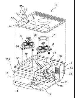
space-saving construction. It is to be noted that where the light from the
light
emitting element 54 will adversely affect the detecting operation of the
infrared
sensor 40, it is recommended to cease the detecting operation of the infrared
sensor 40 during the length of time the light emitting element 54 is active to
emit the
light or, alternatively, to employ a wavelength region of the infrared sensor
40 to be
detected, which is different from the wavelength of light from the light
emitting
element 54.
[0046] Also, since the sensor unit 48 is constructed with the infrared sensor
40 and the light emitting element 54 and includes the printed circuit board 52
for
fixing and electrically connecting the infrared sensor 40 and the light
emitting
element 54 and the unit housing 50 made of the electroconductive metallic
material
CA 02672788 2009-06-15
23 and accommodating therein the printed circuit board 52; since the unit
housing 50
has the shielding portion 50a for electromagnetically shielding the infrared
sensor 40
and the light emitting element 54 both provided on the side of the printed
circuit
board 52 adjacent the second heating coil 8; and since the light guiding means
(the
light guide tube 60 and the light guide portion 36a) is formed integrally with
the
shielding portion 50a so as to protrude in a direction towards the heating
area 35,
not only can the sensor unit 48 be assembled compact in size, but the
assemblage
can be also facilitated, thus rendering the infrared sensor 40 and the light
emitting
element 54 to be hardly affected by noises originating from an inverter and
the
second heating coil 8.
[0047] Fig. 5 illustrates a modified form of the sensor unit 48 shown in Fig.
4,
and the sensor unit 48A shown in Fig. 5 is not provided with the light guide
tube 60
of the sensor unit 48 shown in Fig. 4. The light guide portion 36a is extended
downwardly with the lower opening 36c brought to a position close to the
infrared
sensor 40. A step 36i is formed in the vicinity of the lower end of the light
guide
portion 36a and, when the unit housing 50 is threaded to the heating coil
support
base 36 by means of the screw member 62, a mount 36g below the step 36i
extends through a hole 50b, defined in the shielding portion 50a, with the
light guide
portion 36a engaged consequently with the shielding portion 50a. The inner
wall of
the light guide portion 36a is colored black so that rays of light can be
absorbed
thereby. The convex lens 41 (the light collecting means) is arranged on the
path
along which the infrared rays of light are guided from the article to be
heated A
towards the infrared sensor 40, so that the infrared rays of light emanating
from the
article to be heated A and passing through the infrared incident region 35a
can be
guided towards the infrared sensor 40.
[0048] Since the inner wall of the light guide portion 36a is so colored black
as to absorb the light, the field of view of the infrared sensor 40 is limited
by the
upper opening 36d. By this construction, it is possible not only to simplify
the
CA 02672788 2009-06-15
24
construction, but also to reduce the heat, which will be transmitted from the
second
heating coil 8 and/or the article to be heated A to the infrared sensor 40,
when the
light guide path for the travel of the infrared rays of light therethrough is
formed by a
part of the light guide portion 36a which is a resinous article.
[0049] Also, a rod-like light guide element 67 is inserted and fixed to a
portion
of the inner wall of the light guide portion 36a on one side offset towards
the
frontward direction. This light guide element 67 has, at its lower end, an
incident
face 67a opposed to the light emitting element 54 and also has, at its upper
end, a
light emitting face 67b opposed to the infrared incident region 35a in the top
plate 4a.
Rays of light emerging outwardly from the light emitting face 67b illuminate
the
infrared incident region 35a and, accordingly, the user can notice such light
within
the infrared incident region 35a. Thus, since when viewed from above the body
2,
the infrared incident region 35a is disposed on the straight line passing
across the
center 8e of the second heating coil 8 and the center of the light emitting
face 67b of
the light guide element, which is a region where the rays of light emitted
from the
light emitting element 54 can be viewable, or its proximity and between the
center
8e of the second heating coil 8 and an approximate center of the light
emitting face
67b, it is possible to assuredly place the bottom surface of the article to be
heated A
above the infrared incident region 35a when the bottom surface of the article
to be
heated A is covered by a light emitting portion 67b. It is to be noted that a
light
shielding coating, which is, for example, black in color, may be applied to a
lateral
side face of the light guide element 67 to avoid leakage of light therefrom.
[0050] Fig. 6 illustrates another modified form of the sensor unit 48 shown in
Fig. 4, and the sensor unit 48B shown in Fig. 6 is of a structure, in which a
light
guide element 68 is disposed above the infrared sensor 40 and the light
emitting
element 54.
[0051] The light guide element 68 is formed in an annular shape having its
center formed with a round through-hole 68a, and a part thereof is formed with
a
CA 02672788 2009-06-15
bent portion 68b so as to confront a light emitting portion of the light
emitting
element 54. Rays of light emerging from the light emitting element 54 are
incident
upon the light guide element 68 from an end face of the bent portion 68b, the
light
guide element 68 having the through-hole 68a defined at the center thereof is
5 illuminated in its entirety, and an annulus of light exits towards the
article to be
heated A, with an upper face of the light guide element 68 serving as a light
emitting
face from which that annulus of light emerges outwardly. Also, the infrared
rays of
light from the article to be heated A are incident upon the infrared sensor 40
through
the through-hole 68a of the light guide element 68.
10 [0052] Since the foregoing construction is such that the light from the
light
emitting element 54 is injected; the light guide element 68 capable of
allowing the
light to emerge outwardly in the form of an annulus of light is further
provided; and
the annulus of light guided from the light emitting face of the light guide
element 68
towards the light guiding means (the light guide tube 60 and the light guide
portion
15 36a) exits so as to travel towards the article to be heated A, some
advantages can
be obtained that the amount of light used to illuminate the infrared incident
region
35a can be increased and that the infrared incident region 35a can be
uniformly
illuminated.
[0053] Also, since the infrared rays of light radiated from the article to be
20 heated A are guided towards the infrared sensor 40 through the upper
opening 36d
of the light guide portion 36a and then through the through-hole 68a defined
inside
the light emitting face of the light emitting element 54, it is possible to
avoid the
possibility that the collecting of the infrared rays of light from the article
to be heated
A may be disturbed.
25 [0054] Fig. 7 illustrates a further modified form of the sensor unit 48
shown in
Fig. 4, and the sensor unit C shown in Fig. 7 is of a structure, in which the
light
guide tube 60 in the unit housing 50 is extended to a position adjacent the
printed
circuit board 52 or its proximity, and the infrared sensor 40 and the light
emitting
CA 02672788 2009-06-15
26
element 54, which are positioned in proximity to each other, are accommodated
within a lower extension tube 60c continued from the light guide tube 60.
Also, a
light diffusing ring 70 having a round through-hole 70a is provided above the
infrared sensor 40 and the light emitting element 54, and the infrared sensor
40 is
disposed below the through-hole 70a while the light emitting element 54 is
disposed
below a site other than the through-hole 70a.
[0055] This construction is effective not only to prevent light inside the
appliance or external light leaking through a gap in the unit housing 50 in
the vicinity
of, for example, the connector 58 from being incident upon the infrared sensor
40 to
thereby increase the light coliecting property, but also to reduce the leakage
of the
light emitted from the iight emitting element 54 so that the brightness of the
exit light
from the top plate 4a, which the user can notice, can be increased, since the
unit
housing 50 includes the lower extension tube 60c extending towards the printed
circuit board 52 with the infrared sensor 40 and the light emitting element 54
accommodated within the lower extension tube 60c. Also, since the light
diffusing
ring 70 having the through-hole 70a is provided above the infrared sensor 40
and
the light emitting element 54, and the infrared sensor 40 is disposed below
the
through-hole 70a, the light emitted from the light emitting element 54 is in
the form
of a planar light, not a pencil of light, with the uniformity increased
consequently.
[0056] Fig. 8 illustrates a still further modified form of the sensor unit
shown in
Fig. 4, and the sensor unit 48D shown in Fig. 8 is of a structure, in which a
light
sensor 72 is disposed in the vicinity of the infrared sensor 40, and a
partition wall 74
for separating both of the infrared sensor 40 and the light sensor 72 from the
light
emitting element 54 is formed integrally with the unit housing 50. Also, the
light
guide portion 36a in the heating coil support base 36 has its interior
similarly formed
integrally with a partition wall 36e dividing the interior into two chambers,
and the
light guide portion 36a has its upper end formed with an upper opening 36d and
an
exit port 36f. The top plate 4 has its rear surface printed with a colored
printed film
CA 02672788 2009-06-15
27 35c, which is colored in, for example, a silver color, and the light
emitting region 35b
is not printed with any colored printed film 35c but is formed with a light
diffusing
layer 76. The infrared incident region 35a is not printed with any colored
printed
film 35c. Since the infrared incident region 35a is formed with the printed
film,
which is colored in black or dark brown color, but is capable of transmitting
infrared
rays of light therethrough, for concealing the interior from view, the user
can
recognize the infrared incident region 35a as a black window if the colored
printed
film 35c is of a bright color such as, for example, a silver color.
[0057] Fig. 9 illustrates an induction heating appliance Cl for cooking having
the sensor unit 48D of the structure shown in Fig. 8, and the light guide
portion 36a
in the heating coil support base 36 and the light guide tube 60, both
cooperating
with each other to form the light guiding means, have an overall outer
sectional
shape representing a substantially elliptical shape and, at the same time, a
path (the
light guide portion 36a) of travel of the infrared rays of light incident on
the infrared
sensor 40 and a path (a second light guide portion 36h) of travel of the light
emitted
from the light emitting element 54, which are separated from each other by the
partition walls 36e and 74, have respective horizontal sections representing a
substantially round shape. The respective horizontal sectional shapes of the
light
guide tube 60 and the second light guide tube 60d are identical with those of
the
light guide portion 36a and the second light guide portion 36h. When viewed
from
above the body 2, the infrared incident region 35a and a light emitting region
35b
are positioned at respective locations displaced inwardly of the heating area
35, that
is, inwardly of the outermost periphery of the second heating coil 8 and
forwardly
along the direction forwards and rearwards from the center 8e of the second
heating
coil 8 (which direction is, in the illustrated instance, referred to as a
direction
perpendicular to the front edge 4c of the top unit 4 or in a direction
perpendicular to
the front surface 14a of the body 2) and, when viewed from front of the body
2, the
both are laterally juxtaposed relative to each other in a direction leftwards
and
CA 02672788 2009-06-15
28
rightwards (in a transverse direction). In other words, when viewed from above
(in
a top plan representation), the infrared incident region 35a and the light
emitting
region 35b are juxtaposed relative to each other on respective sides of a
longitudinal
center line Y, which is a straight line passing across the center of the
second
heating coil 8 (the center of the heating area 35) in the direction forwards
and
rearwards (in the longitudinal direction). The transverse center line X in
Fig. 9 is a
straight line extending across the center 35e of the heating area 35 (the
center 8e of
the second heating coil 8 when viewed from above) and parallel to the front
surface
14a of the body 2, and the infrared incident region 35a and the light emitting
region
35b are laid parallel to the straight line X.
[0058] As hereinabove described, since the top plate 4a is formed with the
light emitting region 35b, corresponding to the path of travel of the light
emitted from
the light emitting element 54, and the infrared incident region 35a,
corresponding to
the path of travel of the infrared rays of light to be incident upon the
infrared sensor
40, in a fashion close towards, but separated from each other, not only can
the field
of view of the infrared sensor 40 be narrowed, but the light emitted from the
light
emitting element 54 can be also efficiently guided towards the light emitting
region
35b. Also, influences which the exit light from the light emitting element 54
may
bring about on the infrared sensor 40 can be suppressed.
[0059] Fig. 10 illustrates a yet further modified form of the sensor unit
shown
in Fig. 4, and the sensor unit 48E shown in Fig. 10 differs from the sensor
unit 48D
shown in Fig. 8 in that, as is the case with the construction shown in Fig. 5,
the light
guide portion 36a shown in Fig. 8 is extended downwardly with the lower
opening
36c positioned in proximity to the infrared sensor 40 and that, as shown in
Fig. 11,
the light emitting region 35b and the infrared incident region 35a are
displaced from
the center of the second heating coil 8 in the direction forwards and
rearwards (in
the longitudinal direction) and forwardly. The step 36i is formed in the
vicinity of
the lower end of the light guide portion 36a. When the unit housing 50 is
threaded
CA 02672788 2009-06-15
29
to the heating coil support base 36 by means of the screw member 62, a mount
36g
downwardly of the step 36i is engaged with the shielding portion 50a. By this
construction, the path of travel of the infrared rays of light, limiting the
field of view of
the infrared sensor 40, and the path of travel of light emitted from the light
emitting
element 54 can be formed in a single component part for simplification and,
also,
the heat, which may be transmitted from the second heating coil 8 and the
article to
be heated A to the infrared sensor 40, can be reduced. Also, a rod-like light
guide
element 67 is inserted and fixed to a portion of the inner wall of the light
guide
portion 36a on one side offset towards the frontward direction. This light
guide
element 67 has, at its lower end, an incident face 67a opposed to the light
emitting
element 54 and also has, at its upper end, a light emitting face 67b opposed
to the
infrared incident region 35a in the top plate 4a. Rays of light emerging
outwardly
from the light emitting face 67b illuminate the infrared incident region 35a
and,
accordingly, the user can notice such light within the infrared incident
region 35a.
[0060] Fig. 11 illustrates the second heating coil 8, which is provided with
the
sensor unit E, and its proximity. Although in Fig. 9, the light emitting
region 35b
and the infrared incident region 35a have been shown and described as
juxtaposed
to each other in the direction leftwards and rightwards (in the transverse
direction),
as viewed from front, and have been displaced forwardly from the center of the
second heating coil 8 in the direction forwards and rearwards (in the
longitudinal
direction), the article to be heated A can cover the infrared incident region
35a and
be heated with an increased handling ability if the light emitting region 35b
is
juxtaposed forwardly in the direction forwards and rearwards (in the
longitudinal
direction) from the center of the second heating coil 8 as shown in Fig. 11.
In other
words, the user generally places the article to be heated A with the center of
the
bottom surface thereof matched with the center 8e of the second heating coil
8.
Where in this condition the bottom diameter of the article to be heated A is
sufficiently large enough to permit the bottom surface thereof to cover the
infrared
CA 02672788 2009-06-15
incident region 35a, it is possible to allow the infrared incident region 35a
to be
stably covered with the article to be heated A while the distance from the
position of
the infrared incident region 35a to an end of the bottom surface of the
article to be
heated A in the transverse direction (as viewed from front) remains the same
in
5 either side in the leftward and rightward directions. In the event that the
bottom
diameter of the article to be heated A is not sufficiently large, and the
infrared
incident region 35a cannot be covered when the article to be heated A is
placed with
the center of the bottom surface thereof matched with the center 8e of the
second
heating coil 8, the article to be heated A can be placed at the position where
the
10 infrared incident region 35a can be stably covered with the bottom surface
of the
article to be heated A, and the distance from the position of the infrared
incident
region 35a to that end of the bottom surface of the article to be heated A in
the
transverse direction (as viewed from front) remains the same in either side in
the
leftward and rightward directions by moving the article to be heated A
forwardly
15 while watching the infrared incident region 35a, Also, since the infrared
incident
region 35a is provided between the light emitting region 35b and the center 8e
of the
second heating coil 8, placement of the article to be heated A on the heating
area
so as to cover the light emitting region 35b is effective to assuredly cover
the
infrared incident region 35a with the article to be heated A.
20 [0061] Similarly, not only in the case in which the light emitting region
35b
and the infrared incident region 35a are displaced in the direction forwards
and
rearwards (in the longitudinal direction) from the center of the second
heating coil 8
and forwardly, but also in the case where the light emitting region 35b and
the
infrared incident region 35a are displaced from the center 8e of the second
hearing
25 coil 8, it is preferred that the light emitting region 35b be arranged at a
location
radially outwardly of the center 8e of the second heating coil 8, because the
infrared
incident region 35a can be stably covered with the article to be heated A by
covering
the light emitting region 35b with the article to be heated A.
CA 02672788 2009-06-15
31
[0062] Fig. 12 illustrates a control circuit for the second heating coil 8,
which
can be employed where the sensor unit 48D shown in Fig. 8 or the sensor unit
48E
shown in Fig. 10 is employed. In addition to the control circuit shown in Fig.
3, an
illuminance detecting means 73 adapted to receive an output from the light
sensor
72 is provided, and the control means 44 is operable to control an output from
the
inverter circuit 46 for supplying a high frequency current to the second
heating coil 8
in dependence on an output from the temperature detecting means 42 and an
output from the illuminance detecting means 73.
[0063] In other words, the light sensor 72 is to detect the illuminance (or
the
brightness) of ordinary indoor light, and the illuminance detecting means 73
is
operable in response to an output signal from the light sensor 72 to compare
the
illuminance, detected by the light sensor 72, with a predetermined threshold
value.
In the event that the illuminance detected by the light sensor 72 attains a
value
higher than a predetermined value, it is determined that the article to be
heated A
fails to cover the infrared incident region 35a, in which case the control
means 44
disables a heating control of the second heating coil 8 by the inverter
circuit 46 or
suppresses the output of the second heating coil 8, but in the event that the
illuminance detected by the light sensor 72 attains a value lower than the
predetermined value, it is determined that the article to be heated A covers
the
infrared incident region 35a, in which case the control means 44 performs the
heating control of the second heating coil 8 by the inverter circuit 46.
[0064] Accordingly, the control means 44 performs an output control of the
inverter circuit 46 in response to the output signal from the infrared sensor
40 only
when the illuminance detected by the light sensor 72 is lower than the
predetermined value, thereby to control the heating output from the second
hearting
coil 8 so that the temperature or the temperature gradient of the article to
be heated
A may be lower than a predetermined value.
[0065] By the construction described above, since the light emitting region
CA 02672788 2009-06-15
32
35b is illuminated in the vicinity of the infrared incident region 35a, the
position of
the infrared incident region 35a can easily be noticed and, even when the
indoor
space is dark, the infrared incident region 35a can easily be noticed.
[0066] Also, since the light sensor 72 can detect the illuminance within the
indoor space, it is possible to detect that the article to be heated A is not
in position
to cover the infrared incident region 35a, but where the indoor space is dark,
it is
difficult for the light sensor 72 to detect that the article to be heated A is
not in
position to cover the infrared incident region 35a. However, since even in
such
case, the light emitting region 35b can readily be noticed with eyes due to
the light
emission, the temperature controi of the article to be heated A by means of
the
infrared sensor 40 can be performed stably if the light emitting region 35b is
covered
to permit the infrared incident region 35a to be covered.
[0067] It is to be noted that although the surface area of the light emitting
region 35b is small and, therefore, any displacement in position between the
upper
opening 36d, through which light is projected, and the light emitting region
35b will
be conspicuously visible, the provision of the light diffusing layer in the
light emitting
region 35b in the manner as hereinbefore described can minimize the visibility
of the
displacement in position. The construction in which the light diffusing layer
is
provided will now be described with particular reference to Figs. 13A to 13E.
[0068] The construction shown in Fig. 13A is such that a semitransparent
light diffusing layer 76 is provided over the entire area of the light
emitting region
35b, whereas the construction shown in each of Figs. 13B to 13E is such that
the
light emitting region 35b is provided with a light diffusing layer 76 mixed
together
with a site having a higher light transmittance than that of the light
diffusing layer 76.
[0069] To describe further, the structure shown in Fig. 13B is such that a
center area of the light emitting region 35b is rendered to be a transparent
area 78,
where no light diffusion layer exists; a peripheral area is provided in a
stripe shape
at a location radially outwardly of this center area and is formed by a
CA 02672788 2009-06-15
33
semitransparent annular light diffusing layer 76; and the light transmittance
of the
center area is chosen to be higher than that of the peripheral area.
[0070] Also, the construction shown in Fig. 13C is such that a plurality of
semitransparent round light diffusing layers 76 are provided in the light
emitting
region 35b in a scattered fashion and an area other than the light diffusing
layers 76
is rendered to be a transparent area 78.
[0071] Further, the construction shown in Fig. 13D is such that a center area
of the light emitting region 35b is rendered to be a transparent area 78
having no
light diffusing layer formed therein; a first peripheral area is provided in a
stripe
shape at a location radially outwardly of the center area and is formed by a
semitransparent annular light diffusing layer 76; and a second peripheral area
is
provided in a stripe shape at a location radially outwardly of the first
peripheral area
and is formed by a colored light transmittable layer 80 having a light
transmittance
lower than that of the first peripheral area.
[0072] Yet, the construction shown in Fig. 13E is such that a semitransparent
light diffusing layer 76 is formed in a grid pattern in the transparent area
78 provided
in the light emitting region 35b.
[0073] It is to be noted that although in any one of the constructions shown
respectively in Figs. 13B to 13E, the transparent area 78 is provided in a
part of the
light emitting region 35b, a different light diffusing layer having a light
transmittance
higher than that of the light diffusing layer 76 may be provided in place of
this
transparent area 78.
Industrial Applicability
[0074] Since the induction heating appliance for cooking according to the
present invention is so designed that the region of incidence of the infrared
rays of
light emanating from the article to be heated such as, for example, a pot upon
the
infrared sensor can be easily noticed with eyes, all that is performed by the
user is
to place the article to be heated on the top plate so as to cover the infrared
incident
CA 02672788 2009-06-15
34
region and, hence, the induction heating appliance for cooking according to
the
present invention is useful as an induction heating appliance for home cooking
that
can be built in a household kitchen.