Note: Descriptions are shown in the official language in which they were submitted.
CA 02672836 2009-06-15
WO 2008/076420 PCT/US2007/025762
SUPERABRASIVE CUTTING ELEMENTS WITH ENHANCED
DURABILITY AND INCREASED WEAR LIFE, AND DRILLING
APPARATUS SO EQUIPPED
PRIORITY CLAIM
This application claims the benefit of U.S. Provisional Patent Application
Serial
No. 60/875,698, filed December 18, 2006.
TECHNICAL FIELD
Embodiments of the invention relate to cutting elements and apparatus so
equipped for use in drilling subterranean formations. More particularly,
embodiments
of the invention relate to a polycrystalline diamond or other superabrasive
cutting
element, or cutter, configured for use on a rotary drag bit or other tool used
for earth or
rock boring, such as may occur in the drilling or enlarging of an oil, gas,
geothermal or
other subterranean borehole, and to bits and tools so equipped.
BACKGROUND
There are three types of bits which are generally used to drill through
subterranean formations, including percussion bits (also called impact bits),
rolling
cone bits, including tri-cone bits, and rotary drag bits or fixed cutter
rotary bits
(including core bits so configured). Rotary drag bits conventionally employ
diamond or
other superabrasive cutting elements or "cutters," with the use of
polycrystalline
diamond compact (PDC) cutters being most prevalent.
In addition to conventional, concentric rotary drag and bits, there are other
apparatus employed downhole and generically termed "tools" herein, which may
be
employed to cut or enlarge a borehole or which may employ superabrasive
cutters,
inserts or plugs on the surface thereof as cutters or wear-prevention
elements. Such
tools include, without limitation, bicenter bits, eccentric bits, expandable
reamers, and
reamer wings.
It has been known in the art for many years that PDC cutters perform well on
drag bits and other rotary tools. A PDC cutter typically has a diamond layer
or table
formed under high temperature and pressure conditions to a cemented carbide
substrate
(such as cemented tungsten carbide) containing a metal binder or catalyst such
as
cobalt. The substrate may be brazed or otherwise joined to an attachment
member such
as a stud or to a cylindrical backing element to enhance its affixation to the
bit face.
CA 02672836 2009-06-15
WO 2008/076420 PCT/US2007/025762
2
The cutting element may be mounted to a drill bit either by press-fitting or
otherwise
locking the stud into a receptacle on a steel-body drag bit, or by brazing the
cutter
substrate (with or without cylindrical backing element) directly into a
preformed
pocket, socket or other receptacle on the face of a bit body, as on a matrix-
type bit
formed of WC particles cast in a solidified, usually copper-based, binder as
known in
the art.
A PDC is normally fabricated by placing a disk-shaped, cemented carbide
substrate into a container or cartridge with a layer of diamond crystals or
grains loaded
into the cartridge adjacent one face of the substrate. A number of such
cartridges are
typically loaded into an ultra-high pressure press. The substrates and
adjacent diamond
crystal layers are then compressed under ultra-high temperature and pressure
conditions. The ultra-high pressure and temperature conditions cause the metal
binder
from the substrate body to become liquid and sweep from the region behind the
substrate face next to the diamond layer through the diamond grains and act as
a
reactive liquid phase to promote a sintering of the diamond grains to form the
polycrystalline diamond structure. As a result, the diamond grains become
mutually
bonded to form a diamond table over the substrate face, which diamond table is
also
bonded to the substrate face. The metal binder may remain in the diamond layer
within
the pores existing between the diamond grains or all or a portion of the metal
binder
may be removed, as well known in the art. The binder may be removed by acid
leaching or an electrolytic leaching process. For more background information
concerning processes used to form polycrystalline diamond cutters, the reader
is
directed to U.S. Patent No. 3,745,623, issued on July 17, 1973, in the name of
Wentorf,
Jr. et at.
An embodiment of a conventional rotary drag bit is shown in FIG. 1. The drag
bit of FIG. 1 is designed to be turned in a clockwise direction (looking
downward at a
bit being used in a hole, or counterclockwise if looking at the bit from its
leading end,
or face as shown in FIG. 1) about its longitudinal axis. The majority of
current drag bit
designs employ diamond cutters comprising PDC diamond tables formed on a
substrate, typically of cemented tungsten carbide (WC). State-of-the-art drag
bits may
achieve a rate of penetration (ROP) under appropriate weight on bit (WOB) and
applied
torque, ranging from about one to in excess of three hundred five meters per
hour. A
disadvantage of state-of-the-art PDC drag bits is that they may prematurely
wear due to
CA 02672836 2009-06-15
WO 2008/076420 PCT/US2007/025762
3
impact failure of the PDC cutters, as such cutters may be damaged very quickly
if used
in highly stressed or tougher formations composed of limestones, dolomites,
anhydrites,
cemented sandstones, interbedded formations, also known as transition zones,
such as
shale with sequences of sandstone, limestone and dolomites, or formations
containing
hard "stringers." As noted above, there are additional categories of tools
employed in
boreholes, which tools employ superabrasive cutting elements for cutting, and
which
suffer the same deficiencies in the drilling the enumerated formations. In
many such
formations, other types of cutting structures have been employed in drag bits,
including
small natural diamonds, small so-called "thermally stable" PDC cutters, and
diamond
grit-impregnated metal carbide matrix-type cutting structures of various
configurations.
However, such drag bits provide a much-inferior ROP to PDC cutter-equipped
bits and
so incur substantial additional drilling cost in terms of rig and drilling
crew time on site.
Conventional PDC cutters experience durability problems in high load
applications. They have an undesirable tendency to crack (including
microcracking),
chip, spall and break when exposed to hard, tough or highly stressed geologic
structures
so that the cutters consequently sustain high loads and impact forces. They
are
similarly weak when placed under high loads from a variety of angles. The
durability
problems of conventional PDCs are worsened by the dynamic nature of both
normal
and torsional loading during the drilling process, wherein the bit face moves
into and
out of contact with the uncut formation material forming the bottom of the
wellbore, the
loading being further aggravated in some bit designs and in some formations by
so-called bit "whirl."
The diamond table/substrate interface of conventional PDCs is subject to high
residual stresses arising from formation of the cutting element, as during
cooling, the
differing coefficients of thermal expansion of the diamond and substrate
material result
in thermally induced stresses. In addition, finite element analysis (FEA) has
demonstrated that high tensile stresses exist in a localized region in the
outer cylindrical
substrate surface and internally in the substrate. Both of these phenomena are
deleterious to the life of the cutting element during drilling operations as
the stresses,
when augmented by stresses attributable to the loading of the cutting element
by the
formation, may cause spalling, fracture or even delamination of the diamond
table from
the substrate.
CA 02672836 2009-06-15
WO 2008/076420 PCT/US2007/025762
4
Further, high tangential loading of the cutting edge of the cutting element
results
in bending stresses on the diamond table, which is relatively weak in tension
and will
thus fracture easily if not adequately supported against bending. The metal
carbide
substrate on which the diamond table is formed may be of inadequate stiffness
to
provide a desirable degree of such support.
The relatively rapid wear of diamond tables of conventional PDC cutters also
results in rapid formation of a wear flat in the metal carbide substrate
backing the
cutting edge, the wear flat reducing the per-unit area loading in the vicinity
of the
cutting edge and requiring greater weight on bit (WOB) to maintain a given
rate of
penetration (ROP). The wear flat, due to the introduction of the substrate
material as a
contact surface with the formation, also increases drag or frictional contact
between the
cutter and the formation due to modification of the coefficient of friction.
As one
result, frictional heat generation is increased, elevating temperatures in the
cutter and
initiating damage to the PDC table in the form of heat checking while, at the
same time,
the presence of the wear flat reduces the opportunity for access by drilling
fluid to the
immediate rear of the cutting edge of the diamond table.
There have been many attempts in the art to enhance the durability of
conventional PDC cutters by modification of cutting face geometry,
specifically in the
vicinity of the cutting edge which engages the formation being drilled. By way
of
example, the reader is directed to U.S. Patent RE32,036 to Dennis (the >036
patent);
U.S. Patent No. 4,592,433 to Dennis (the >433 patent); and U.S. Patent No.
5,120,327
to Dennis (the >327 patent). In FIG. 5A of the >036 patent, a cutter with a
beveled
peripheral edge is depicted, and briefly discussed at Col. 3, lines 51-54. In
FIG. 4 of the
>433 patent, a very minor beveling of the peripheral edge of the cutter
substrate or
blank having grooves of diamond therein is shown (see Col. 5, lines 1-2 of the
patent
for a brief discussion of the bevel). Similarly, in FIGS. 1-6 of the >327
patent, a minor
peripheral bevel is shown (see Col. 5, lines 40-42 for a brief discussion of
the bevel).
Such bevels or chamfers were originally designed to protect the cutting edge
of the
PDC while a stud carrying the cutting element was pressed into a pocket in the
bit face.
However, it was subsequently recognized that the bevel or chamfer protected
the
cutting edge from load-induced stress concentrations by providing a small load-
bearing
area which lowers unit stress during the initial stages of drilling. The
cutter loading
CA 02672836 2009-06-15
WO 2008/076420 PCT/US2007/025762
may otherwise cause chipping or spalling of the diamond layer at an
unchamfered
cutting edge shortly after a cutter is put into service and before the cutter
naturally
abrades to a flat surface, or "wear flat," at the cutting edge.
It is also known in the art to radius, rather than chamfer, a cutting edge of
a PDC
5 cutter, as disclosed in U.S. Patent 5,016,718 to Tandberg. Such radiusing
has been
demonstrated to provide a load-bearing area similar to that of a small
peripheral
chamfer on the cutting face.
For other approaches to enhance cutter wear and durability characteristics,
the
reader is also referred to U.S. Patent No. 5,437,343 to Cooley et al. (the
>343 patent);
and U.S. Patent No. 5,460,233 to Meany et al. (the >233 patent), assigned to
the
assignee of the present invention. In FIGS. 3 and 5 of the >343 patent, it can
be seen
that multiple, adjacent chamfers are formed at the periphery of the diamond
layer (see
Col. 4, lines 31-68 and Cols. 5-6 in their entirety). In FIG. 2 of the >233
patent, it can
be seen that the tungsten carbide substrate backing the superabrasive table is
tapered at
about 10-15E to its longitudinal axis to provide some additional support
against
catastrophic failure of the diamond layer (see Col. 5, lines 2-67 and Col. 6,
lines 1-21 of
the >233 patent). See also U.S. Patent No. 5,443,565 to Strange for another
disclosure
of a multi-chamfered diamond table.
It is known that conventionally providing larger chamfers on cutters enhances
durability, but at the same time reduces ROP and undesirably increases
required WOB
for a given ROP. The increased WOB translates to more energy applied to the
drilling
system, and specifically the drag bit which, in turn, stimulates cutter
damage.
U.S. Patent No. 5,706,906 to Jurewicz et al., assigned to the assignee of the
present invention, describes PDC cutters of substantial depth or thickness, on
the order
of about 1.778 mm (0.070 inch) to 3.81 mm (0.150 inch) and having cutting
faces with
extremely large chamfers or so-called "rake lands" on the order of not less
than about
1.27 mm (0.050 inch), as measured radially along the surface of the rake land.
A PDC cutter as described in the `906 Patent has demonstrated, for a given
depth of cut and formation material being cut, a substantially enhanced useful
life in
comparison to prior art PDC cutters due to a greatly reduced tendency to
catastrophically spall, chip, crack and break. It has been found that the
cutter in PDC
form may tend to show some cracks after use, but the small cracks do not
develop into a
CA 02672836 2009-06-15
WO 2008/076420 PCT/US2007/025762
6
catastrophic failure of the diamond table as typically occurs in PDC cutters.
This
capability, if fully realized, would be particularly useful in a cutter
installed on a drag
bit to be used on hard rock formations and softer formations with hard rock
stringers
therein (mixed interbedded formations).
While such PDC cutters with their large rake lands have shown some promise in
initial field testing, conclusively proving the durability of the design when
compared to
other cutters of similar diamond table thickness but without the large rake
land, these
PDC cutters also demonstrated some disadvantageous characteristics which
impaired
their usefulness in real-world drilling situations. Specifically, drill bits
equipped with
these PDC cutters demonstrated a disconcerting tendency, apparently due to the
extraordinarily great cutting forces generated by contact of these cutters
with a
formation being drilled, to overload drilling motors, other bottomhole
assembly (BHA)
components such as subs and housings, as well as tubular components of the
drill string
above the BHA.
Further, bits equipped with these PDC cutters often drilled significantly
slower,
that is to say, their rate of penetration (ROP) of the formation was far less
than, the
ROP of bits equipped with conventional PDC cutters, and also exhibited
difficulty in
drilling through hard formations for which they would be otherwise ideally
suited. It
appears that the exterior configuration of these thick diamond table cutters,
although
contributing to the robust nature of the cutters, may be less than ideal for
many drilling
situations due to the variable geometry of the arcuate rake land as it
contacts the
formation and attendant lack of "aggressiveness" in contacting and cutting the
formation. It is conceivable, as demonstrated in the cutting of metal with
similarly
shaped structures, that in plastic formations these PDC cutter may simply
deform the
material of the formation face engaged by the cutter, forming a plastic "prow"
of rock
ahead and flanking the cutter, instead of shearing the formation material as
intended.
Therefore, despite the favorable characteristics exhibited by these PDC
cutters,
their utility in efficiently cutting the difficult formations for which its
demonstrated
durability is ideally suited remains, as a practical matter, unrealized over a
broad range
of formations and drilling conditions.
U.S. Patent No. 5,881,830 to Cooley, assigned to the assignee of the present
invention, describes PDC cutters having cutting faces with a first portion
transverse to a
longitudinal axis of the cutter and a second portion comprising a planar
engagement
CA 02672836 2009-06-15
WO 2008/076420 PCT/US2007/025762
7
surface or buttress plane oriented at a small, acute angle to the first
portion and having a
cutting edge along at least a portion of its periphery. These PDC cutters are
described
as durable, fairly aggressive and providing a more consistent performance over
the life
of the cutter than the PDC cutters described in the `906 Patent, but their
large chamfers
result in an unacceptable reduction in aggressivity in cutting, leading to a
reduced ROP.
In addition, U.S. Patent No. 6,935,444 to Lund et al., assigned to the
assignee of
the present invention, discloses the use of multiple, adjacent chamfers having
an arcuate
surface located therebetween along a cutting edge of a PDC cutter. Such a
geometry
has been demonstrated to inhibit initial chipping of a PDC cutter along the
cutting edge,
prolonging the life thereof.
However, and as noted with regard to the PDC cutter designs discussed above,
there remains a need for a robust superabrasive cutter which will withstand
cutting
stresses in the difficult formations referenced above and exhibit reduced wear
tendencies while drilling effectively with, and without damage to,
conventional,
state-of-the-art bottomhole assemblies and drill strings, while providing
commercially
viable, consistent ROP.
During laboratory testing, it has been observed that conventional, 45 chamfer
angle cutters with conventional chamfer depths on the order of, for example,
0.406 mm
(0.016 inch), commonly experience premature cutter damage and failure when the
wear
flat extends inwardly of the inner boundary of the chamfer. Specifically, an
increased
incidence of spalling and chipping of the PDC table has been observed. This is
a
particular problem in the aforementioned highly stressed or tougher
formations,
interbedded formations and formations containing hard stringers.
Several factors are believed to contribute to these types of cutter failure.
First,
during a drilling operation, downward force is applied to the competent
formation
under WOB as a result of chamfer and cutter backrake angle, maintaining the
PDC
table in compression and adding to cutter integrity. However, when the inner
edge or
boundary of the chamfer is worn away, the chamfer component of the compressive
forces is diminished, with a consequent potential for high tensile shear
forces to be
present at the cutting face, resulting in the aforementioned spalling and
chipping.
Further, when the inner edge or boundary of the chamfer is worn away, a sharp
edge or
corner at the cutting face is presented to the formation, similar to that
presented by an
unchamfered cutter. Any vertical (parallel to the plane of the cutting face)
forces acting
CA 02672836 2009-06-15
WO 2008/076420 PCT/US2007/025762
8
on this sharp edge will translate as vertical tensile shear across the cutting
face,
resulting in a spalled cutter.
In addition, heat checking in the PDC table, due to the initiation of a large,
relatively wide wear flat is particularly significant toward the rear of the
wear flat and
may result in significant breakage of the PDC table at the back and sides
thereof.
DISCLOSURE OF THE INVENTION
In one embodiment, a cutter according to the invention comprises a
superabrasive table mounted to a supporting substrate of a metal material such
as a
cemented metal carbide. The cutter has a longitudinal axis extending generally
transversely to the plane of the cutting face. In a cylindrical cutter
configuration, the
longitudinal axis would be coincident with the center line of the cutter. A
chamfer is
provided adjacent a least a portion of a periphery of the superabrasive-table,
the
chamfer lying at a relatively steep chamfer angle of greater than about 45 to
the
longitudinal axis of the cutter, or with respect to the line of the sidewall
of the cutter
(assuming the cutter has a sidewall parallel to the longitudinal axis of the
cutter). The
chamfer may be arcuate, or planar. The chamfer depth, in conjunction with the
relatively steep chamfer angle, is sufficient to maintain a wear flat outside
the inner
boundary of the chamfer on the cutting face, yet small enough to avoid
substantially
compromising aggressivity of the cutter.
By employing a relatively steep chamfer angle, aggressivity of the cutter is
maintained, as force applied to the formation under the cutter is more
concentrated,
compressing less of the formation and resulting in less sliding friction
between the
cutter and the formation, maintaining a sharp cutting edge. Required WOB may
be
reduced with the use of relatively steep chamfer angles, as they penetrate the
formation
to a desired depth of cut more efficiently, reduce friction and consequent
heat, and
prolong cutter life.
With relatively steep chamfer angles, a smaller, smaller in length wear flat
is
generated in comparison to wear flats generated on conventionally chamfer
angled
cutters, reducing heat checking resulting from thermal stress on the PDC
table.
By containing the wear flat outside the inner boundary of the chamfer and
within the chamfer envelope, forces on the cutter substantially parallel to
the cutting
face are distributed over the chamfer surface, reducing the incidence of
cutter spalling.
CA 02672836 2011-10-26
9
This may be due to the ability of such a cutter to withstand significantly
greater magnitude
of drilling vibrations. The term "chamfer envelope" as used herein with
respect to wear
flat development on the cutting face of the superabrasive table, means the
portion of the
cutting face outside the inner boundary of the chamfer. Stated another way and
in the
context of use of the cutter for drilling a subterranean formation, the term
means an area
on the cutting face between the portion of the cutting edge in contact with a
formation
during drilling and the adjacent inner boundary of the chamfer.
It has also been noted by the inventors that cutters configured with steep
chamfer
angles according to some embodiments of the invention may be particularly
suited to
placement on relatively low load areas of a bit where enhanced cutting
efficiency is
required, such as on the nose, shoulder and gage regions of the bit. Other
embodiments of
cutters of the invention may be particularly suited to placement on high load
areas of the
bit, such as on a region of the bit proximate the longitudinal axis, generally
termed the
cone region, where there are relatively high forces on the cutters due to low
cutter
redundancy at a given radius on the bit face, and cutters have a greater area
of cut.
Accordingly, cutters according to various embodiments of the invention may be
placed on the face of a bit in consideration of the work demanded of a cutter
at a given
location and chamfer angle and size.
Accordingly, in one aspect there is provided a structure for use in drilling
subterranean formations, the structure comprising:
at least one cutting element having a superabrasive table bonded to a
supporting
substrate, the superabrasive table extending transverse to a longitudinal axis
of the cutting
element, and including:
a cutting face having a periphery including a first chamfer along at least a
portion thereof extending to proximate a cutting edge;
a sidewall extending from proximate the cutting edge to a boundary with
the supporting substrate, the boundary lying at least about 0.127 mm (0.005
inch)
longitudinally to the rear of the cutting edge;
wherein the first chamfer is oriented at an angle, relative to the
longitudinal axis of the cutting element, of greater than about 45 , wherein
the first
chamfer has a depth, measured parallel to the longitudinal axis from an inner
boundary of
the first chamfer to the cutting edge, of no less than about 0.0508 mm (0.002
inch) and no
greater than about 0.635 mm (0.025 inch); and
either another chamfer outward of the first chamfer and closer to the
CA 02672836 2011-10-26
9a
cutting edge than the first chamfer at a lesser angle relative to the
longitudinal axis and of
a lesser depth, or a radiused edge outward of the first chamfer and closer to
the cutting
edge than the first chamfer.
Rotary drag bits and other fixed cutter drilling tools incorporating
embodiments of
cutters of the invention are also encompassed thereby.
BRIEF DESCRIPTION OF THE DRAWINGS
The foregoing and other features and advantages of the invention will become
apparent to persons of ordinary skill in the art upon reading the
specification in
conjunction with the accompanying drawings, wherein:
FIG. I is a perspective view of a conventional drag bit;
FIGS. 2a through 2d depict, respectively, a side view, an enlarged side view,
a
front view, and a perspective view, of an embodiment of a superabrasive cutter
of the
present invention;
FIG. 3 depicts the embodiment of FIGS. 2a through 2d of the superabrasive
cutter
of the present invention in use engaging a subterranean fonnation;
CA 02672836 2009-06-15
WO 2008/076420 PCT/US2007/025762
FIG. 4 depicts a partially worn cutter according to the embodiment of FIGS. 2a
through 2d of the present invention;
FIG. 5 depicts a side view of another embodiment of the cutter of the present
invention;
5 FIG. 5a depicts an enlarged side view of a portion of a cutter of FIG. 5
engaging
a subterranean formation;
FIG. 6 depicts a side view of yet another embodiment of the cutter of the
present
invention;
FIG. 7 is a graph of a theoretical relationship between cutter chamfer angle
and
10 cutter back rake as affecting required weight on bit to achieve a given
depth of cut;
FIG. 8 is a graph of a theoretical wear flat analysis for predicting wear flat
surface area as a function of chamfer angle for a given cutter back rake
angle;
FIG. 9 is schematic depiction of a 45 chamfer angle cutting face of a
conventional PDC cutter in comparison to a 60 angle chamfer angle cutting
face of a
PDC cutting element in accordance with an embodiment of the present invention,
showing the effect of the present invention on wear flat generation and an
enhanced
ability to maintain depth of cut within the chamfer; and
FIG. 10 is a schematic drawing of cutter placement on a single blade of a drag
bit, showing in black the relative formation area being cut by each cutter on
the blade.
MODE(S) FOR CARRYING OUT THE INVENTION
Referring to FIG. 1, a conventional fixed-cutter rotary drill bit 10 includes
a bit
body 12 that has generally radially projecting and longitudinally extending
wings or blades
14, which are separated by junk slots 16. A plurality of PDC cutters 18 are
provided on the
leading faces of the blades 14 extending over the 20 face of the bit body 12.
The face 20 of
the bit body 12 includes the surfaces of the blades 14 that are configured to
engage the
formation being drilled, as well as the exterior surfaces of the bit body 12
within the
channels and junk slots 16. The plurality of PDC cutters 18 maybe provided
along each of
the blades 14 within pockets 22 formed in the blades 14, and may be supported
from
behind by buttresses 24, which may be integrally formed with the bit body 12.
The drill bit 10 may further include an API threaded connection portion 30 for
attaching the drill bit 10 to a drill string (not shown). Furthermore, a
longitudinal bore (not
shown) extends longitudinally through at least a portion of the bit body 12,
and internal
CA 02672836 2009-06-15
WO 2008/076420 PCT/US2007/025762
11
fluid passageways (not shown) provide fluid communication between the
longitudinal bore
and nozzles 32 provided at the face 20 of the bit body 12 and opening onto the
channels
leading to junk slots 16.
During drilling operations, the drill bit 10 is positioned at the bottom of a
well bore
hole and rotated while weight on bit is applied and drilling fluid is pumped
through the
longitudinal bore, the internal fluid passageways, and the nozzles 32 to the
face 20 of the
bit body 12. As the drill bit 10 is rotated, the PDC cutters 18 scrape across
and shear away
the underlying earth formation. The formation cutting mix with and are
suspended within
the drilling fluid and pass through the junk slots 16 and up through an
annular space
between the wall of the bore hole and the outer surface of the drill string to
the surface of
the earth formation.
The inventors contemplate that embodiments of the cutter of the invention will
be used primarily on rotary drag bits as described above and including without
limitation core bits, bi-center bits, and eccentric bits, as well as on fixed
cutter drilling
tools of any configuration, including without limitation reamers or other hole
opening
tools. As used herein, the term "bit" includes all such bits and tools.
It is also contemplated by the inventors that embodiments of the cutter of the
invention may be used at various locations on a bit or other drilling tool,
such as on
cone, nose, shoulder and gage regions of a bit or tool face, and may be
positioned as
primary cutters along a rotationally leading edge of a blade of a bit, or as
so-called
"back up" cutters rotationally trailing one or more primary cutters on a
blade. Such
back up cutters may be positioned to exhibit an exposure the same as, greater
than, or
less than, an associated primary cutter. Reference is made to FIGS. 2a through
2d
which depict a side view, an enlarged side view an end view and a perspective
view,
respectively, of one embodiment of the cutter of the present invention. The
cutter 201
is of a shallow frustoconical configuration and includes a circular diamond
layer or
table 202 (e.g., a polycrystalline diamond compact) bonded (i.e., sintered) to
a
cylindrical substrate 203 (e.g., tungsten carbide). The interface between the
diamond
layer and the substrate is, as shown, comprised of a diametrically extending
recess
within the substrate 203 into which a portion of the diamond table 202
projects (shown
in broken lines in FIG. 2a), defining a so-called "bar" of diamond in
accordance with
U.S. Patent No. 5,435,403, assigned to the assignee of the present invention.
Of course,
many other interface geometries are known in the art and suitable for use with
the
CA 02672836 2009-06-15
WO 2008/076420 PCT/US2007/025762
12
invention. The diamond layer 202 is of a thickness "T," as shown in FIG. 2a.
The
substrate 203 has a thickness "T2," also as shown in FIG. 2a. The diamond
layer 202
includes an arcuate chamfer 208 with a chamfer angle 0 relative to the
sidewall 206 of
the diamond layer 202 (parallel to the longitudinal axis or center line 207 of
the cutter
201) and extending forwardly and radially inwardly toward the longitudinal
axis 207.
The chamfer angle 0 in the illustrated embodiment is defined as the included
acute
angle between the surface of chamfer 208 and the sidewall 206 of the diamond
layer
which, in the illustrated embodiment, is parallel to longitudinal axis 207.
The chamfer
angle O may be in the range of greater than about 45E to about 85E. It is
currently
believed that a particularly suitable range of chamfer angles O is about 50E
to about
750.
The dimensions of the chamfer are significant to performance of the cutter.
The
inventors have found that the Depth D, of the chamfer 208 should be at least
about
0.0508 mm (0.002 inch) and no more than about 0.635 mm (0.025 inch), measured
from a line transverse to the longitudinal axis of the cutter at the inner
boundary of the
chamfer to the outer periphery of the cutting edge in a direction along or
parallel to the
longitudinal axis, or the side wall of the cutter if the cutter is
substantially cylindrical.
It is significant that the wear flat of the cutter be maintained within the
chamfer or,
stated another way, to maintain the wear flat of the cutter outside of the
inner boundary
of the chamfer on the cutting face.
Diamond table 202 also includes a cutting face 213 having a flat central
area 211 radially inward of chamfer 208, and a cutting edge 209. Between the
cutting
edge 209 and the substrate 203 resides a portion or depth of the diamond layer
referred
to as the base layer 210 having a thickness T3 (FIG. 2c), while the portion or
depth D,
(FIG. 2a) between the flat central area 211 of cutting face 213 and the base
layer 210
having the thickness T, is referred to as the chamfer layer 212. The term
"layer" is one
of convenience only for physical description, as the various "layers" of the
diamond
table are, in fact, formed as one integral mass, as known in the art. However,
it is
known to layer the diamond table with different sized diamond grit for
different
characteristics, although such grit layers may not necessary correspond to the
layers of
the diamond table 202 as described herein.
CA 02672836 2009-06-15
WO 2008/076420 PCT/US2007/025762
13
The central area 211 of cutting face 213, as depicted in FIGS. 2a, 2b, 2c and
2d,
is a substantially flat surface oriented perpendicular to longitudinal axis
207
In the depicted cutter, the thickness T, of the diamond layer 202 may lie in
the
range of about 0.762 mm (0.030 inch) to about 3.048 mm (0.120 inch), with a
particularly suitable thickness range currently believed to be from about
1.524 mm
(0.060 inch) to about 2.032 mm (0.080 inch). Such a diamond layer thickness
results in
a cutter which, in combination with the aforementioned chamfer size and angle
ranges,
exhibits substantially improved impact resistance, abrasion resistance and
erosion
resistance. Further, the foregoing thickness ranges are nominal ranges,
without taking
into consideration protrusions of the diamond layer 202 into the substrate 203
or
vice-versa, such as occur when a non-planar diamond layer/substrate interface
topography is employed, as is well known in the art. In any case, beyond a
minimum
diamond layer thickness sufficient to provide the aforementioned advantages,
the
diamond layer thickness employed is not significant to the invention.
The boundary 215 of the diamond layer and substrate to the rear of the cutting
edge 209 is desirably at least about 0.127 mm (0.005 inch) longitudinally to
the rear of
the cutting edge. The inventors believe that the aforementioned minimum
cutting edge
to interface distance is desirable to ensure that the area of highest residual
stress (i.e.,
the area to the rear of the location where the cutting edge of the cutter
contacts the
formation being cut) is not subject to early point loading, and to ensure that
an
adequate, rigid mass of diamond and substrate material supports the line of
high loading
stress.
As shown in FIGS. 2a-2d, the sidewall 217 of the cutter 201 is parallel to the
longitudinal axis 207 of the cutter. Thus, as shown, chamfer angle O equals
angle D,
the angle between chamfer 208 and axis 207 (FIG. 2a). However, cutters of the
present
invention need not be circular or even symmetrical in cross-section, and the
cutter
sidewall, or a portion extending to the rear of the chamfer in the
superabrasive table and
sidewall of the supporting substrate may not always parallel the longitudinal
axis of the
cutter. Thus, the chamfer angle may be set as angle O or as angle D, depending
upon
cutter configuration and designer preference. A significant aspect of the
invention
regarding angular orientation of the chamfer is the presentation of the
chamfer to the
formation at an angle effective to achieve the advantages of the invention in
terms of
maintaining an aggressive cutting structure while preserving cutter integrity.
CA 02672836 2009-06-15
WO 2008/076420 PCT/US2007/025762
14
Another optional but desirable feature of the embodiment of the invention
depicted in FIGS. 2a through 2d is the use of a low friction finish on the
cutting
face 213, including chamfer 208. A suitable low friction finish is a polished
mirror
finish which has been found to reduce friction between the diamond table 202
and the
formation material being cut and to enhance the integrity of the cutting face
surface.
For further detail on the aforementioned finish, the reader is directed to
U.S. Patent No.
5,447,208 issued to Lund et al., assigned to the assignee of the present
invention, for
additional discussion and disclosure of polished superabrasive cutting faces.
Another optional cutter feature usable in the invention and depicted in broken
lines in FIG. 2a is the use of a backing cylinder 216 face-bonded to the back
of
substrate 203. This design permits the construction of a cutter having a
greater
dimension (or length) along its longitudinal axis 207 to provide additional
area for
bonding (as by brazing) the cutter to the bit face, and thus to enable the
cutter to
withstand greater forces in use without breaking free of the bit face. Such an
arrangement is well known in the art and disclosed in U.S. Patent 4,200,159.
However,
the presence or absence of such a backing cylinder does not affect the
durability or wear
characteristics of the inventive cutter.
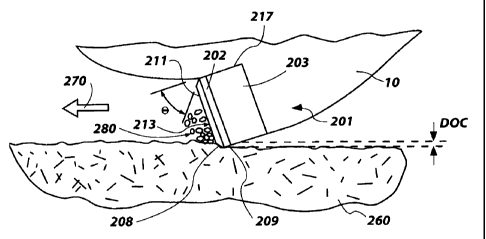
FIG. 3 depicts an embodiment of the cutter 201 of the invention in use on a
bit
10. The cutter 201 has a diamond table 202 sintered onto a tungsten carbide
substrate
203. The diamond table 202 has a chamfer 208 which has a chamfer angle O with
respect to sidewall 217. The cutter 201 has a cutting face 213 with a central
flat area
211. Cutting face 213 cuts the rock 260, contacting it at cutting edge 209. As
the bit 10
with cutter 201 moves in the direction indicated by arrow 270, the cutter 201
cuts into
rock 260, resulting in rock particles or chips 280 sliding across the cutting
face 213.
The cutting action of the cutter 201 results in a cut being made in the rock
260, the cut
having depth of cut "DOC." The cutting action that takes place when the
invented
cutter is used is a shearing action such as occurs with unchamfered cutters or
cutters
with smaller depth chamfers, due to the relatively high chamfer angle, which
provides
an aggressive cutter which is also robust.
It is contemplated that different chamfer angles O may be selected in order to
increase either cutting face strength or depth of cut. As O is increased,
cutting edge
loading per unit area increases and depth of cut should increase, resulting in
a
corresponding increase in the rate of penetration through the formation for a
given
CA 02672836 2009-06-15
WO 2008/076420 PCT/US2007/025762
WOB. Conversely, as O is decreased, cutting edge loading per unit area
decreases,
depth of cut decreases, and rate of penetration decreases for a given WOB.
In FIG. 4, an end view of the embodiment of cutter 201 from its diamond table
202 or cutting face 213 is provided. The cutting edge 209, chamfer 208, inner
boundary
5 205 of the chamfer, and central cutting face area 211 are all depicted. As
the cutter 201
is used, it will develop a shorter, relatively narrow and shallow wear flat W
that is only
slightly broader adjacent the cutting edge 209 or periphery of the cutter
(i.e., adjacent
the cutter side wall) than it is at the inner portion of the chamfer adjacent
but outside
inner boundary 205, in comparison to conventionally chamfered cutters with a
45
10 chamfer angle, wherein the wear flat is significantly longer and deeper,
extending inside
of inner boundary 205 as shown in broken lines W' on FIG. 4 and extending
farther to
the rear of the cutting edge into the sidewall 206 of the diamond table 202 as
well as to
a greater width (not shown).The cutter of the invention may be embodied in a
half
cutter (180 cutting face), a third cutter (120 cutting face), a quarter
cutter (90 cutting
15 face) or any other portion of a full cylindrical cutter. Alternatively, a
cutter which
embodies the inventive concept that is not cylindrical in shape may be formed.
It is
contemplated that a cutter with a steeply angled chamfer in accordance with
embodiments of the invention may be constructed with various cutting face
shapes
including without limitation a square, rectangular, triangular, pentagonal,
hexagonal,
heptagonal, octagonal, otherwise shaped as an n-sided polygon (where n is an
integer),
oval, elliptical, or other shape, in a cross section taken orthogonal to the
longitudinal
axis of the cutter.
Embodiments of the cutter of the invention improve cutter performance by
providing a cutter which has been found to cut a subterranean formation at a
rate of
penetration (ROP) equivalent to that of a typical conventional cutter of
similar diameter
and composition, with a similar-sized chamfer, but at a conventional, 45
chamfer
angle, in combination with the ability to cut a substantially greater volume
of formation
material before wearing to a point where effective cutting action ceases.
Embodiments
of the cutter of the invention have also been found, in laboratory testing, to
exhibit
greater wear resistance as well as resistance to spalling, chipping, heat
checking and
microcracking of the PDC table than prior art cutters having a similar chamfer
depth
but conventional45 chamfer angles.
CA 02672836 2009-06-15
WO 2008/076420 PCT/US2007/025762
16
The superabrasive table may be made from polycrystalline diamond or thermally
stable polycrystalline diamond, depending upon the application. Further, a
polycrystalline diamond table may have catalyst or binder removed only to a
selected
depth below the cutting face and along the side wall of the table, as is known
in the art.
In lieu of a polycrystalline diamond table, a table or compact structure of
any of the
following types may be used in the cutter: diamond film (including CVD), cubic
boron
nitride, and a structure predicted in the literature as C3N4 being equivalent
to known
superabrasive materials. Cutters according to embodiments of the invention may
be
manufactured using the conventional processes as briefly mentioned in the
Background
hereof, such processes being well known to those of ordinary skill in the art.
Of course,
if materials other than diamond particles are used for the cutter table, or if
materials
other than a cemented carbide, such as tungsten carbide (WC), are used for the
substrate, then the manufacturing process may be modified appropriately. The
inventors contemplate that numerous substrates other than tungsten carbide may
be
used to make the invented cutter. Appropriate substrate materials include any
cemented
metal carbide such as carbides of tungsten (W), niobium (Nb), zirconium (Zr),
vanadium (V), tantalum (Ta), titanium (Ti), tungsten Ti) and hafnium (Hf).
A further embodiment of a cutter 301 according to the present invention and
exhibiting a substantially planar chamfer 308 on a superabrasive table 302
across a
portion of cutting face 313 and extending to a cutting edge 309 is depicted in
FIG. 5.
Such a substantially planar chamfer 308 may be formed simultaneously with the
superabrasive table 302, or machined thereafter. Alternatively, a portion of
the
superabrasive table 302 of such a cutter, or of circular cutters, may be laser-
stitched to
produce a weakened corner which will break away from the superabrasive table
edge
preferentially, resulting in the desired chamfer profile and cutting edge 309
in terms of
depth and angle. Of course, an annular chamfer 308 may be employed, as
depicted in
FIG. 5a. As depicted in both FIGS. 5 and 5a, the superabrasive table 302 and
supporting substrate 303 may be configured in a so-called CSE (carbide
supported
edge) configuration, wherein the superabrasive table 302 and substrate 303 are
each
configured at the leading end with an angled sidewall for enhanced support of
the
superabrasive table while still providing a clearance or "relief' angle a of
about 10 to
15 to the rear of the cutting edge 309, as depicted in FIG. 5a when the
cutter 301 is
back raked.. As may readily be seen from FIG. 5a, the angled side wall 303S of
CA 02672836 2009-06-15
WO 2008/076420 PCT/US2007/025762
17
substrate 303 in combination with a relatively high chamfer angle of (for
example) 60
and cutter back rake angle of (for example) 25 may be used to provide a
relatively very
tough cutter configuration which also drills fast and maintains the substrate
side wall
303S out of contact with the formation being drilled for a prolonged period of
time.
Such an arrangement reduces the potential for damaging heat generation
resulting from
sliding contact of the substrate with the formation immediately behind the
superabrasive table. CSE cutter configurations are offered by Hughes
Christensen, an
operating unit of the assignee of the present invention, and are more fully
described in
previously noted U.S. Patent No. 5,460,233.
~ Yet another embodiment of a cutter 401 according to the present invention
and
exhibiting a larger, inner chamfer 408 on the cutting face 413 of the diamond
table 402
angled in accordance with the present invention and bounded at its radially
outer
periphery by a much smaller, less steeply angled outer chamfer or radiused
edge 408', is
depicted in FIG. 6. Such an arrangement may be used to provide an aggressive
cutter in
accordance with the present invention, while the outer chamfer or radiused
edge 408'
may prevent initial chipping of cutting edge 409 until at least a small wear
flat has been
established. Edge 408' may, in some embodiments, be characterized as a sharp,
"honed" edge with an associated small chamfer or radius only sufficiently
large to
preclude edge damage during initial engagement of the cutter with the
formation as
drilling is initiated.
The actual angle of contact of the cutting face of embodiments of cutters of
the
invention with the formation (and thus the effective back rake) is determined
in part by
the chamfer angle, and in part by the back rake angle of the cutter itself, as
is known in
the art. In comparison to conventional superabrasive cutters of similar
chamfer depth,
wherein the chamfer is relatively quickly removed and, subsequently, only the
back
rake angle of the cutter itself contributes to compression of the
superabrasive table, the
prolonged chamfer life of cutters according to embodiments of the present
invention
helps maintain the superabrasive table in compression for an extended period,
significantly contributing to cutter integrity over an extended wear life
thereof.
FIG. 7 of the drawings demonstrates a computer analysis of predicted
relationship of chamfer angle in combination with cutter back rake angle for
various
combinations of chamfer angles and cutter back rakes in terms of WOB required
for a
given DOC. The modeled rock was Sierra White Granite, and drilling was
simulated at
CA 02672836 2009-06-15
WO 2008/076420 PCT/US2007/025762
18
an ROP of 6.1 m/hr (20 ft/hr), at a rotational speed of 60 RPM, using a
chamfer depth
of 0.406 mm (0.016 inch) and a depth of cut DOC of 1.702 mm (0.067 inch). As
can
be seen, for relatively low cutter back rake angles, on the order of 5 , 10
and 15 ,
chamfer angles in the 55 to 70 range offer a significant reduction in
required WOB
for a given DOC. This reduction in required WOB for a desired DOC, while
maintaining the superabrasive table cutting face in a compressive stress state
as
described above, provides enhanced cutting efficiency and may prolong cutter
life,
although this has not been confirmed.
It should be noted that cutters according to embodiments of the present
invention are significantly beneficial when used to drill hard formations
exhibiting
above about 1054.9 Kg/cm (15 Kpsi) unconfined compressive strength, and even
more
so when used in ultrahard formations exhibiting an unconfined compressive
strength in
excess of about 1758.1 Kg/cm (25Kpsi). Such cutters are also particularly
suitable for
use in drilling abrasive formations, where smaller wear flats are desirable to
maintain
ROP. For example, laboratory tests using cutters according to embodiments of
the
present invention on Sierra White granite, which exhibits a 1828.4 Kg/cm (26
Kpsi)
UCS and is very abrasive, produced excellent results.
A graphic illustration of the longevity benefits of configuring a cutter in
accordance with embodiments of the present invention is presented in FIG. 8.
FIG. 8
graphically depicts results of a theoretical wear flat analysis performed with
respect to a
16mm diameter PDC cutter oriented at a 20 cutter back rake. The graph
indicates a
significant benefit in terms of reduction of wear flat area of using either a
0.406 mm
(0.016 inch) or 0.457 mm (0.018 inch) chamfer depth with a chamfer angle of 60
or
70 (curves B through E), in comparison to the same cutter with a .406 mm
(0.016 inch)
depth 45 chamfer (curve A). In FIG. 8, in the inset to the graph, the first
number
associated with each curve A, B, etc., designates the chamfer angle, and the
second
number, the chamfer depth in inches.
FIG. 9 of the drawings is a schematic depiction of an enlarged portion of a
PDC
cutting element and a portion of the cutting face, showing a conventional 45
chamfer
(termed Std. 45 Chamfer) angle with a superimposed 60 chamfer angle (termed
a
"Steep Chamfer" in the drawing figure) according to an embodiment of the
present
invention. The PDC cutting element is back raked, as is conventional when
cutting a
formation, with respect to the horizontal line of cutter travel moving from
right to left
CA 02672836 2009-06-15
WO 2008/076420 PCT/US2007/025762
19
on the drawing sheet. As can readily be seen, the conventional45 chamfer,
over time,
results in the formation of a relatively large (long, front to back) wear
flat, denoted as
"Large Wear Flat" in the figure, while the steeper chamfer of the present
invention
results in a substantially smaller (shorter) wear flat, denoted as "Small Wear
Flat" in the
figure. Further, a comparison of the "short Chamfer envelope" of the
conventional 45
chamfer to the "extended Chamfer envelope" of the steeper chamfer according to
the
present invention makes it clear that the present invention enables
beneficially
maintaining the depth of cut within the chamfer envelope by enabling a
substantially
larger depth of cut as well as sustaining greater wear of the PDC table before
the
chamfer envelope is exceeded. As noted previously, in most instances if the
wear flat
can be maintained within the chamfer envelope, catastrophic failure of the
cutter due to
spalling and chipping of the cutting face is avoided. The longer the period of
time, in
terms of cutter usage during drilling operations that the wear flat is
maintained within
the chamfer envelope, the longer the leading chamfer edge remains beneficially
in
compression. Once the wear flat increases and wears into the cutting face
inside the
inner boundary of the chamfer, increased incidences of spalling of the PDC
table result.
Referring now to FIG. 10 of the drawings, benefits of employing different
embodiments of cutters according to the present invention will be described.
FIG. 10 is
a schematic view of cutter placement along an edge of a single blade of a drag
bit. The
cutter designated Cl is closest to the longitudinal axis L of the bit, while
the cutter
designated Cl and 36 on FIG. 10 are not sequential, as the missing numbers are
attributable to cutters on other blades of the bit. According to industry
practice, the
"number 1" cutter is the cutter immediately adjacent the bit axis, while
succeeding
cutter numbers are assigned to cutters at ever-greater radial distances from
the axis,
regardless of on which blade any particular cutter is located. The inner
arcuate line on
each cutter is the inner boundary of the chamfer envelope. On each cutter, the
black
area depicts a scalloped area of cut, the irregular area of cut shape being
attributable to
a path previously cut through the formation by another, radially adjacent
cutter on
another blade. It can also be seen that the area of cut on, for example, the
number C 1
and C4 cutters on the nose region of the bit is substantially greater than,
for example,
the area of cut on number C24 and C28 cutters on the bit shoulder. As can be
readily
seen, for cutters number C24 and C28 the area of cut is largely contained
within the
chamfer envelope.
CA 02672836 2009-06-15
WO 2008/076420 PCT/US2007/025762
Thus, drilling performance for cutters number C24 and C28 is very dependent
on chamfer angle for drilling performance in terms of cutting efficiency and
durability.
Conventionally, such cutters may have relatively high back rakes (note the
somewhat
elliptical shapes of cutter numbers C30, C36, reflecting high back rakes),
resulting in a
5 tough cutter in terms of durability but compromising drilling efficiency
when a
conventional 45 chamfer is employed. By using a cutter according to an
embodiment
of the invention using a relatively steep chamfer angle and maintaining the
area of cut
within the chamfer envelope, drilling efficiency is enhanced, less frictional
heat is
generated and prolonged cutter life results.
10 It has been observed by the inventors that, while cutters according to
embodiments of the invention drill faster than conventionally chamfered
cutters, in
some instances use of such cutters on a drill bit may result in higher torque
rates and
increased vibration. In such instances, it may be desirable to employ so-
called depth of
cut control technology as is offered by Hughes Christensen Company as "EZ
Steer"
15 technology, as described in U.S. Patents No. 6,298,930 and No. 6,460,631,
each
assigned to the assignee of the present invention. Such technology may be used
to
prevent over-torquing of the bit or the bit drilling too fast, and provides
greater cutter
durability. Other approaches include the use of additional cutters, and to
employ such
cutters on so-called "heavy set" bits with a large number of cutters and
enhanced cutter
20 redundancy.
While the present invention has been described and illustrated in conjunction
with a number of specific embodiments, those skilled in the art will
appreciate that
variations and modifications may be made without departing from the principles
of the
invention as herein illustrated, described and claimed. The present invention
may be
embodied in other specific forms without departing from its spirit or
essential
characteristics. The described embodiments are to be considered in all
respects as only
illustrative, and not restrictive. The scope of the invention is, therefore,
indicated by
the appended claims, rather than by the foregoing description. All changes
which come
within the meaning and range of equivalency of the claims are to be embraced
within
their scope.