Note: Descriptions are shown in the official language in which they were submitted.
CA 02672844 2009-06-16
-1-
Field of the invention
The present invention relates to a single-use syringe of
the self-destructible or passive self-lockable type,
namely self-locking thereof occurs after the syringe has
been used a first time, independently of the user's will.
Prior art
Syringes are a type of instrument widely used in the
medical and health sector in order to administer drugs,
insulin, etc., to patients in need thereof. For health
safety reasons it is desirable that this type of syringe
should be used once only so that diseases or illnesses
cannot be passed from one patient to another. However,
this is not always the case, especially amongst drug-
dependent persons who usually use the syringes again on
more than one occasion, with the consequent medical risk
which this involves. Such reuse is feasible because in
conventional syringes there is nothing to prevent or least
discourage reuse thereof. The existence of single-use
syringes which self-destruct or self-lock automatically
when used a first and only time theoretically solves this
problem of preventing reuse of already used syringes.
However, it is also desirable that syringes intended for
this purpose should have other additional characteristics:
1. Be tamper-proof for those users who attempt to reuse
them. Otherwise, a user could interfere with them,
deactivating the self-destructing or self-locking systems,
with the aim of being able to reuse them indefinitely.
2. Be of the passive type, namely have a design such
that total or partial locking and breakage occurs
passively, irrespective of the user's will.
CA 02672844 2009-06-16
-2-
3. Be easy to break when disposed of and difficult to
break during normal use.
4. Have a low manufacturing cost. In the prior art it
is possible to find a large number of documents which
describe single-use syringes. However, practically none of
them have been successful commercially owing to the fact
that sanitary syringes are subject to a further
constraint: their cost. Syringes for sanitary use are
mainly acquired by the national health authorities in
various countries for use in health centres, hospitals,
etc. For said national health authorities cost is a
factor of prime importance such that a single-use syringe
which has a cost much higher than that of the current
syringes is unacceptable, even despite its undoubted
advantages in terms of health safety. Consequently, in
order for a single-use syringe to be successful in the
health sector, its manufacturing cost must be
substantially the same as that of conventional syringes,
or, expressed differently, it must be substantially as
easy to manufacture as conventional syringes.
For example, the international publication W002/22194 in
the name of Li describes a self-destructible syringe.
However, its design is complex, requiring a large number
of internal parts, which increases its manufacturing cost
to an unacceptable level.
The international publication W089/00057 describes a self-
lockable syringe whose locking system is based on a series
of grooves and tongues arranged inside the plunger and
barrel. However, since the locking action occurs only
CA 02672844 2009-06-16
-3-
once the plunger has already performed a certain part of
its stroke, and not before, this syringe can be easily
tampered with by a user who wishes to use it again, by
simply extracting the plunger before initial use and
cutting the tongues of the barrel using a knife or cutter
such as to make the locking system unusable.
Other documents, such as US20040199113, US20040176722 and
ES1051002U, describe a syringe which has a weakened part
at the end of the plunger, intended to break under
pressure when the plunger reaches the end of its stroke.
However, a careful user may not manage to break this
weakened part so that the syringe would remain locked only
if actively desired by the user. Moreover, a user who
wishes to cause locking of the .syringe when used the first
time would have to apply additional pressure to the
plunger at the end of its stroke, causing a pressure-
induced haematoma in the patient.
Finally, the document ES 1055675U, which is considered to
be the most closely related prior art, describes a syringe
which is locked by means of tongues on the plunger which
engage inside grooves located at the top and bottom ends
of the barrel. Owing to the presence of grooves at the
top of the barrel which prevent passage of the plunger if
an attempt is made to remove it before initial use,
tampering with the syringe is impossible. Moreover,
locking of the syringe occurs automatically after first
use independently of the user's will. However, this
syringe, owing to the design of its tongues and grooves,
at the time of use requires the user to exert a relatively
high additional pressure in order to overcome the
resistance offered by the tongues and grooves to passage
CA 02672844 2009-06-16
-4-
of the piston and thus inject the liquid into the patient,
this being frequently the cause of an undesirable
haematoma in the injected zone.
It would be desirable, therefore, to provide a novel
syringe which is devoid of the disadvantages of syringes
of the prior art and in particular which has
characteristics which prevent the syringe from being
deformed or do not require the use of excessive pressure
which causes a "surge" effect when the liquid is injected,
thereby avoiding the formation of haematomas in the
patient.
Summary of the invention
The problem to be solved by the present invention is that
of providing a single-use syringe which overcomes the
drawbacks of existing syringes according to the prior art
and, more specifically, preventing the formation of
haematomas in the patient, while maintaining the
characteristics of being self-locking after initial use,
difficult to tamper with and simple in terms of design.
The solution consists in the fact that the inventors have
created a syringe which maintains the desirable
characteristics mentioned - i.e. self-locking after
initial use, difficult to tamper with and simple design -
by providing a syringe which comprises a barrel which has
inside at least two protrusions in the form of rings with
a general circular rim shape which have a variable inner
radius and triangular or near triangular cross-section and
are located respectively at the top and bottom of the
barrel on its inner side and a plunger which comprises a
plurality of ribs, each of which has a height which is
CA 02672844 2009-06-16
-5-
reduced by the amount needed to allow the plunger to be
inserted in a close-fitting manner through the space
defined by the variable inner.radius of the barrel rings.
By means of these characteristics it is possible to
provide a syringe with the advantages indicated, avoiding
in particular the formation of haematomas in the patient
owing to the present design of rings and ribs which
minimises the resistance to passage of the plunger, and a
manufacturing cost which is substantially similar to that
of conventional syringes.
Consequently, a first aspect of the invention relates to a
single-use syringe which comprises:
a) a barrel (10) which has an inner surface which defines
a chamber for retaining a fluid;
b) a plunger (1) which comprises an elongated body, said
elongated body comprising a plurality of longitudinal ribs
(2), and
c) a piston (3) which is connected to the end of the
plunger close to the needle, the outer surface of the
piston forming a fluid-tight connection with the inner
surface of the barrel, characterised in that:
the barrel comprises at least two rings situated on the
inner side of the barrel, at least one being situated on
the distal part (8) and at least one being situated on the
proximal part (9) of the barrel relative to the needle,
said rings having the general shape of a circular rim (see
general diagram in Figure 10) with an outer radius (R)
coinciding with the radius of the inner side of the barrel
CA 02672844 2009-06-16
-6-
and a variable inner radius (r),-and
in that each one of the longitudinal ribs_ (2) of the
plunger has a height which is constant along its entire
length, but different from that of at least one of the
other ribs, said height being suitable on each rib for
allowing insertion of the plunger (1) through the space
defined by the variable inner radius of the said rings
(8,9) of the barrel in a close-fitting manner.
The two rings mentioned may surround the entire inner
perimeter of the barrel, although they preferably do not
surround it completely, having a general crescent shape
which is more or less closed.
Brief description of the drawings
Figure 1: Figure 1 shows successive views, in positions at
90 intervals, of the plunger used in the single-use
syringe according to the present invention. In this
figure it can be seen how the plunger (1) comprises a
plurality of ribs (2), preferably four in number, which
extend longitudinally along the plunger as far as its end
part, where the piston (3) is situated, said piston being
typically a rubber part, separated from the-plunger by a
connecting piece (4). The end of the plunger close to the
needle has a weakened zone in the form of an orifice which
will generally have a variable shape, preferably polygonal
shape (5), with the aim of favouring easy breakage thereof
at the corners of the polygon. In the embodiment shown in
the Figure, said orifice is shown with a triangular shape.
Each of the ribs has a different height (broken lines
(6)), which height is suitable in each case for allowing
insertion of the plunger in a close-fitting manner through
CA 02672844 2009-06-16
-7-
the space defined by the barrel rings which have a
variable inner radius. Preferably, the length of the
plunger ribs will also be different, being longer in those
cases where the ribs project towards the needle in such a
way as to form the part of the plunger provided with an
inner orifice which is preferably polygonal as defined
above (see the 0 and 180 views in Figure 1).
Figure 2: Figure 2 shows a further embodiment according to
the invention which includes an optional tongue (7) which
protrudes slightly from the piston so as to increase its
locking capacity. In this case also the weakened zone in
the form of an orifice situated at the end of the plunger
close to the needle has been shown with a hexagonal shape.
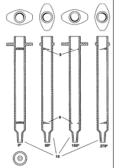
Figure 3: Figure 3 also shows views, in positions at 90
intervals, of the barrel used in the single-use syringe
according to the invention. In said figure it is possible
to see the two rings with a substantially triangular
cross-section according to the invention situated on the
inner, top part (8) and inner bottom part (9) of the
barrel. In a preferred embodiment of the invention, these
rings have a substantially triangular shape, in particular
the shape of a right-angled triangle, one of the catheti
corresponding to the inner wall of the cylinder, the other
cathetus being situated perpendicularly to the inner wall
of the barrel in the zone closest to the needle and so
that the hypotenuse is forced to be a kind of inclined
surface which may be straight or slightly curved so that
the plunger slides smoothly during its travel towards the
end close to the needle, while once said piston has passed
beyond said ring it will be difficult for it to move
backwards again.
CA 02672844 2009-06-16
-8-
In a preferred embodiment of the invention, shown in
Figure 3, these rings are incomplete rings which do not
completely close the inner circumference of the barrel and
which have a variable radius which has a maximum value on
one of the sides of the barrel (0 view), intermediate
value on the two sides situated at 900 with respect to the
first side (90 and 270 views) and minimum or
substantially zero value on the side opposite to the first
side (180 view).
Figure 4: Figure 4 shows a needle suitable for use in
connection with the syringe according to the present
invention.
Figure 5: Figure 5 shows an optional cap - present in a
preferred embodiment of the invention - which may be used
with the single-use syringe according to the invention.
This cap has the characteristic feature that it has a
substantially conical shape with one side widened so as to
facilitate insertion of the needle when not in use. This
cap has a substantially conical shape with one side
extended in the form of a claw, being in reality a
protuberance of the cylinder segment type terminating in a
sphere segment such that, upon insertion of the needle,
the needle engages inside the cap in a direction
perpendicular to the way in which it is then inserted.
Namely, instead of inserting the needle in a single
direction, as occurs with the caps of the prior art, the
user will perform engagement in a direction perpendicular
to the shank of the cover and for this reason will never
risk being pricked.
CA 02672844 2009-06-16
-9-
Figures 6-8: Figures 6 to 8 show the syringe assembled and
in the operating condition. Figure 6 shows the position
of the plunger when the user is injecting liquid, such
that the piston (3) is situated half way along its stroke.
In Figure 7, the plunger has reached the end of its stroke
and the piston (3) is locked by the bottom ring. Figure 8
shows the plunger broken along its weakened part as a
result of an attempt to extract it after it has been
locked.
Figure 9: Figure 9 shows a three-dimensional view of the
cap according to Figure 7.
Figure 10: Figure 10 is a geometrical illustration of a
circular rim showing its inner radius (r) and outer radius
(R).
Detailed description of the invention
Below the preferred embodiments of the invention, which
are provided solely by way of illustration and do not
limit the scope of the invention in any way, are
described.
Plunger:
The plunger is shown in detail in Figure 1. In said
figure it can be seen that the plunger comprises:
- an elongated body which defines a longitudinal axis,
said elongated body comprising a plurality of longitudinal
ribs (2) which extend substantially along the entire
length of the plunger, and each one of the longitudinal
ribs (2) of the plunger has a height which is constant
along its entire length, but different from the height of
CA 02672844 2009-06-16
-10-
the other ribs, said height being suitable for allowing
insertion of the plunger (1) in a close-fitting manner
through the space defined by the said variable-radius
rings (8, 9) of the barrel, the height of each one of said
rings being reduced by the amount necessary for allowing
insertion of the plunger in a close-fitting manner through
the space defined by the rings of the barrel; the ribs are
preferably four in number since this is the number of ribs
present in conventional syringes; however, the invention
is not limited by the number of ribs and any number of
ribs is acceptable, provided that their number and height
is variable in such a way that the plunger can be inserted
in a close-fitting manner through the space defined by the
barrel rings which in turn also have a variable inner
radius; the plunger also comprises.a weakened zone which
is situated preferably at the distal end of the plunger
body and which may have any form, being preferably an
orifice with a polygonal - generally triangular or square
- shape;
- a connecting piece (4) which joins the plunger to the
piston (3); and
- a piston (3), usually a rubber part, the outer surface
of which forms a fluid-tight connection with the inner
surface of the barrel.
Figure 2 shows an alternative embodiment of the plunger,
comprising an additional tongue which projects slightly
from the piston so that it increases the capacity for
locking the plunger by means of the barrel rings.
Barrel:
CA 02672844 2009-06-16
-11-
The syringe barrel is shown in detail in Figure 3. This
Figure 3 also shows views, in positions at 90 intervals,
of the barrel used in the single-use syringe according to
the invention. In said figure it is possible to see the
two rings with a substantially triangular cross-section
and variable radius situated respectively on the inner top
part (8) and inner bottom part (9) of the barrel. Said
rings may be completely closed, but preferably they are
not closed and have a crescent shape; the rings have a
substantially triangular cross-section and the general
shape of a circular rim with a variable inher radius so
that the outer radius of each ring will always be the
inner radius of the barrel, with which it makes integral
contact, while the inner radius of each ring will be
variable so as to minimise the total surface area of the
ring so that it offers the least possible resistance to
passage of the plunger, while causing breakage in the case
of improper use, so that, preferably, they have a minimum
inner radius on one of the sides of the barrel (see 0
view), an intermediate radius on the two sides situated at
90 from the first side (see 90 and 270 views) and an
inner radius which has a maximum value or coincides with
the outer radius (in which case the thickness will be
substantially zero) on the side opposite to the first side
(see 180 view). The general shape of the profile or
cross-section of the rings is that of a wedge or triangle
as explained above so that it is possible to insert the
plunger inside the barrel, but not extract it easily.
In an alternative embodiment of the invention, the said
rings (8, 9) of the barrel are not continuous, but are
formed by more than one section with a discontinuous
shape.
CA 02672844 2009-06-16
-12-
The position of the rings on the inner surface of the
barrel may vary so that it is possible to determine the
volume amount of liquid which can be injected into the
user before locking of the plunger occurs. Therefore,
although it is normally desirable that the top ring should
be situated close to the distal end of the barrel relative
to the needle with the aim of maximizing the useful
volume, the bottom ring may be situated in a position
close to the proximal end of the barrel relative to the
needle, being separated from said end close to the needle
by a greater or smaller distance, and in all cases
preferably within the first third of the length of the
barrel with respect to the needle. In this way, if the
bottom ring is situated in a position on the barrel
further away from the end close to the needle, locking of
the plunger will occur when a smaller amount of liquid has
been injected into the user. If, on the other hand, the
bottom ring is situated in a position closer to the
proximal end of the plunger relative to the needle, there
is a greater useful volume of liquid which can be injected
before locking of the plunger occurs, such that a drug-
dependent user could take advantage of this fact in order
to use the syringe again repeatedly without reaching the
plunger locking position. Preferably, the bottom ring
will be situated in a position close to the end of the
first third of the length of the barrel, with respect to
the end close to the needle.
Cap
The cap of the syringe, which is optional although present
in a preferred embodiment of the invention, has a
substantially conical shape with a widened side prolonged
CA 02672844 2009-06-16
-13-
in the form of a claw, being in reality a protuberance of
the cylinder segment type terminating in a sphere segment
so that, upon insertion of the needle, the needle engages
inside the cap in a direction perpendicular to the
direction in which it is then inserted. Namely, instead
of inserting the needle in a single direction, as occurs
with caps of the prior art, the user will perform
engagement in a direction which is perpendicular to the
shank of the cover and in this way never risks being
pricked. Once the user has performed engagement in a
substantially horizontal direction, the shape of the claw
of the cap prevents the needle from coming out of said cap
at the top or on the sides and directs the needle towards
the cone situated in the vertical plane downwards where it
will be fixed in position, avoiding any risk of pricking
one's fingers.
Syringe
The syringe according to the invention comprises a plunger
with the characteristics described above, which is
inserted in a close-fitting manner inside a barrel having
the characteristics also described above. The syringe
will be provided with a needle which may be supplied
together with the rest of the syringe or separately
therefrom. When the plunger is inserted inside the
barrel, the plunger must be situated so that the lowest-
height rib coincides with the largest-radius side of the
rings of the barrel; the rib situated on the opposite
side, which will be the rib with the smallest or no
reduction in height, will coincide with the side where the
rings have a substantially zero radius and the
intermediate ribs will have an intermediate size matching
the radius corresponding to that of the barrel ring at
CA 02672844 2009-06-16
-14-
each respective point. In this way it will be possible to
insert the plunger in a close-fitting manner inside the
barrel, since the barrel rings are semi-rigid so as to
allow the piston to pass through them in the direction
towards the end of the barrel close to the needle, but
prevent it from passing through in the return direction
towards the end distant from the needle. Once inserted,
the outer surface of the piston (3) forms a substantially
fluid-tight closure with the inner surface of the barrel.
The syringe will be used by the user with the plunger
inserted inside the barrel so that the piston has passed
through the top ring of the barrel, but not the bottom
ring (Figure 6) In this way, the user will be able to
draw the corresponding liquid by introducing the syringe
needle into said liquid and extracting the plunger to the
height necessary for drawing off the desired quantity of
liquid, the stroke of the plunger being limited by the top
ring (9) of the barrel.
The procedure for using the syringe will be as follows:
1. Initially the piston is situated between both
crescent-shaped rings so that there is an air chamber
between the needle and the piston, called "dead space".
2. After introducing the needle into the container with
distilled water or similar liquid the plunger is moved in
the direction away from the needle, drawing off the liquid
which remains inside the barrel, together with an air
zone.
3. Said liquid is inserted inside a container with the
CA 02672844 2009-06-16
-15-
dry extract, without moving the plunger to the end of its
stroke.
4. The mixture is collected again once the dry extract
has dissolved in the distilled water.
5. The air is extracted from the inside of the syringe.
6. The needle is inserted in the patient's body and the
liquid is injected into the patient's body using the
conventional method.
7. When the piston reaches the end of its stroke, it is
lightly retained in said position. The syringe and needle
are extracted from the patient's body.
8. Once extracted from the patient, the needle is
inserted.inside its cap and the plunger is pulled lightly
so as to cause breakage thereof. Should this not be
performed voluntarily and an attempt be made to use the
syringe again, upon attempting to draw off the distilled
water the plunger will break owing to the action of the
crescent-shaped ring which retains the piston.
Similarly, the syringe according to the invention cannot
be easily tampered with by the user since, should the user
attempt to tamper with it prior to initial use, upon
trying to extract the plunger from the barrel, the piston
(3) will come up against the top ring (8) of the barrel,
preventing extraction thereof and also causing breakage of
the plunger by means of the aforementioned weakened part
should the user persist in the attempt to extract it.
CA 02672844 2009-06-16
-16-
In this way the invention described provides a syringe
which has the advantages mentioned, namely a simple
design, ability to self-lock after initial use, guarantee
of safety in medical and sanitary terms and capacity to
resist tampering prior to use thereof.