Note: Descriptions are shown in the official language in which they were submitted.
CA 02673063 2009-07-24
1.0 BACKGROUND OF THE INVENTION
1.1 Field of invention use
The idea described in this invention relates to control of the initial tension
into a
flexible elastic element at each drive pulley. Elastic element could be a
fabric carcass or
steel wire rope. The invented embodiment for control and adjustment of the
initial tension
comprises electro-mechanical arrangement that has to be located at the points
where the
above mentioned control and adjustment of initial tension becomes most
effective. The
embodiment of this invention is aimed to avoid "slipping effect" and
maintaining better
control of the power sharing between the unlimited numbers of the intermediate
drives.
1.2 Prior Art
Providing of an initial tension level for flexible elastic elements (moved by
a drive
pulley), so far is performed by using a single take-up unit with winch or
ballast, or
combination of both. Using a single fix size take-up is proved as a successful
method as
long as the system includes one or small number of drives located close each
other. In
case of using more drives located at very long distances away each other, the
existing
method, of using one fix take-up system, becomes less and less reliable. In
the case of
few dozens or higher number of drives, the above described system (one single
fix take-
up) can not withstand the combination of the physical effects like variation
the tension
CA 02673063 2009-07-24
2
forces and vibrations associated with a variety of the landscape at very long
transportation system. The task of control and power sharing over huge number
of drives
becomes very complex. This is in terms of great number of variables involved
during the
starting, stopping, unstable feed, landscape differences and the elasticity of
the
transporting element. The problem of power sharing control becomes more
complex
when the effects of different stretching level from point to point take place.
The unlimited
combination of such stretching waves spreading along the transporting system
making
situation uncontrollable.
2.3 The invention.
The invention presents embodiment which is incorporated with a conventional
fix size
take-up. This invention represents additional arrangement which has
flexibility for self
adopting tensioning force and is located in vicinity to each drive. This
method allows
compensating of any deviation of the basic initial tension for each drive to
its individual
needs.
The embodiment indicates any change of the sag level as a function of the
local
deviated tension into the flexible elastic element. While the tension is
changing the
embodiment's indicator moves to a new position respectively to the sag level.
By this
movement the new tension is created. The embodiment is able of increasing or
reducing
the tension into the flexible elastic element asymptotically. The new tension
level stops
stretching waves and sends the signal to the located in vicinity the drive
pulley torque
analyzer. This is changing the torque level on the shaft of the drive pulley,
which is
located in the vicinity to this embodiment. Since the torque level of the
drive pulley is re-
adjusted the embodiment's tension stabilizer returns to initial "zero"
position (see part No
6 at Fig No 1). The change is completed by sending the message/signal to the
central
control system for re-adjustment of the power sharing for the rest of the
drive pulleys.
The "zero" position is the point associated with the location of the
embodiment's tension
stabilizer/indicator based on the calculated forces level at stable
environment (i.e. no
acceleration or deceleration of the conveying system). By this way the
embodiment
stabilizes local drive pulley torque to a new required level.
3.0 SUMMARY OF THE INVENTION
3.1 The name
The name of the invention is: ETS.
The abbreviated form ETS means: Electromechanical Tension Stabilizer
3.2 Aim of the invention
The aim of the invention is using the electromechanical arrangement for an
initial tension
control. In addition the invented embodiment is aimed to serve following
functions:
CA 02673063 2009-07-24
3
a) To allow sequential start-up
b) To allow proper power sharing.
c) To avoid belt overstressing.
d) To avoid slipping effect on the drive pulley.
e) To avoid spreading of a vibration waves along the flexible elastic element.
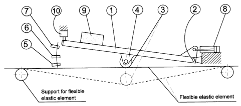
3.3 The components of the ETS.
The specified components of the ETS arrangement covered by this invention and
used
for this particular application are as follows:
1) Pivoted frame.
2) Pivoting arrangement.
3) Pulley/Roller
4) Holding Pulley/Roller bracket
5) Bottom proximity switch
6) Zero position proximity switch
7) Top proximity switch
8) Universal choke
9) Ballast
10) Emergency switch
3.4 General description of the concept.
The idea of this invention is to indicate, to adjust and to stabilize the
initial tension
level into a flexible elastic element at each drive pulley individually. A
flexible elastic
element is used as a vehicle for transportation of a bulk material. In order
to cause
movement of the flexible elastic element the drive pulleys are used. The
transferring of
motion effect from drive pulleys to a flexible elastic element is requiring
certain initial
tension.
Initial tension at each drive pulley comprises two components. One, is the
mutual (for
all drive pulleys) the conventional take-up system located at the tail of the
transporting
system. The second component is the electromechanical tension stabilizer
(ETS). This
component is located in vicinity of each drive house (see Fig 1) and allows
maintaining
proper level of the initial tension at each drive pulley individually.
Additional functions of each electromechanical tension stabilizer are:
(a) Providing the necessary information to the control system. helping to
distribute power
respectively to each of the drive pulleys,
(b) Avoiding of spreading a vibration waves along the flexible elastic
element.
The ETS device is adjusting the initial tension of the flexible elastic
element by
following process.
CA 02673063 2009-07-24
4
The Pulley/Roller of the ETS device (part No 3) installed on the pivoted frame
(part
No 1) clamping the flexible elastic element down (Fig 1). In this arrangement
the ETS
device is able to indicate the tension change of the flexible elastic element.
Any
difference in the tension is reflected by a sag change and as result of it
tilting the ETS's
pivoting frame (part No 1) to a new position. By tilting the pivoting frame
(under sag
change) the ETS adjusting locally the initial tension level. While the Pivoted
frame (part
No 1) is tilted, the Proximity switches (parts No 5, 6 or 7) signaling the
control system
about the movement. As result of it, the control system transfers signal to
the drive
located in vicinity of the ETS. The drive torque of the located in vicinity
driven pulley, is
changed to a new level.
At the same time, the control system readjusting the total torque share of all
other drives
to a new balance.