Note: Descriptions are shown in the official language in which they were submitted.
CA 02673393 2009-07-21
FRAME STRUCTURE FOR VEHICLE
FIELD OF THE INVENTION
The present invention relates to an improvement in frame structure for a
vehicle.
BACKGROUND OF THE INVENTION
There is a conventionally-known vehicle body frame structure for a vehicle,
which is intended to reduce the weight of a vehicle and to reduce the
manufacturing costs (refer to, for example, Japanese Patent Application
Publication No. 2006-103370). The vehicle body frame structure described in
Japanese Patent Application Publication No. 2006-103370 has a vehicle body
frame including: a front frame portion which supports a front-wheel drive
system; a center frame portion which forms a space for occupants; and a rear
frame portion which supports a rear-wheel drive system. In the center frame
portion, the structure of an underfloor frame is formed to be a two-layer
structure having an upper portion and a lower portion. The upper portion
includes lower frames and side square-U-shaped frames, and the lower portion
includes subframes and upper side frames.
In the vehicle body frame structure described in Japanese Patent Application
Publication No. 2006-103370, the structure of the underfloor frame in the
center
frame portion is formed to be the two-layer structure having the upper and
lower portions. This structure sufficiently secures the rigidity of the
underfloor
frame, but increases the height of the floor, thus leading to an increase in
the
height of the seats for the occupants. On the other hand, in order to enhance
the
traveling performance required for vehicles such as MUVs (multi utility
vehicle),
WH-13533/cs
CA 02673393 2009-07-21
-2-
it is desirable that the vehicles have a low floor and a low center of gravity
in
addition to an improvement in rigidity of the vehicle body frame.
The present invention has been made in view of the above-described problems,
and an object of the present invention is to provide a frame structure for a
vehicle
capable of reducing the heights of a floor and of occupant seats so as to
provide a
low floor and a low center of gravity while securing the rigidity of a vehicle
body
frame.
SUMMARY OF THE INVENTION
A first aspect of the present invention provides a frame structure for a
vehicle
including: a vehicle body frame; a pair of occupant seats being arranged side
by
side in a vehicle width direction in the vehicle body frame, and constituting
a
driver's seat and a passenger seat; and a center pipe passing between the
driver's
seat and the passenger seat and being arranged in a front-rear direction
substantially on a center line of a vehicle body in the vehicle body frame.
A second aspect of the present invention provides the following
characteristics in
addition to the configuration of the first aspect. Specifically, the frame
structure
for a vehicle further includes: a lower frame being disposed to extend in the
front-rear direction in both of left and right lower portions of the vehicle
body; a
pair of left and right side frames extending in the front-rear direction
outside the
lower frame in the vehicle width direction; and a pair of side pipes each
connecting two portions of a corresponding one of the side frames in the front-
rear direction. Moreover, in the frame structure for a vehicle, the center
pipe is
arranged above the lower frame to extend in the front-rear direction
substantially on the center line of the vehicle body.
A third aspect of the present invention provides the following characteristics
in
addition to the configuration of the first or second aspect. Specifically, in
the
frame structure for a vehicle, the center pipe includes: an upper center pipe
extending to the front of the vehicle body from a frame constituting, behind
the
occupant seats, the vehicle body frame; a down center pipe extending upward
and frontward from a part, below and between the occupant seats, of a frame
WH-13533/cs
CA 02673393 2009-07-21
-3-
constituting the lower frame; an upright center pipe extending rearward and
upward from a portion, in front of the occupant seats, of the lower frame; and
a
front center pipe extending rearward and downward from a frame constituting,
in front of the occupant seats, the vehicle body frame. Moreover, the upper
center pipe, the down center pipe, the upright center pipe, and the front
center
pipe are joined together at a joint point in front of the occupant seats.
A fourth aspect of the present invention provides the following characteristic
in
addition to the configuration of any one of the first to third aspects.
Specifically,
the frame structure for a vehicle further includes a pair of left and right
front
upper frames extending upward from front ends of the front lower frames,
thereafter extending rearward and then being connected to the front upper
cross-
member, so as to cover a front portion of the vehicle body from above.
Moreover, in the frame structure for a vehicle, the front center pipe is
formed
into the two branches extending frontward respectively to the left and right
from
the joint point so as to be connected to the front upper cross-member
respectively
in vicinities of left and right joint portions of the front upper frames to
the front
upper cross-member.
A fifth aspect of the present invention provides the following characteristic
in
addition to the configuration of any one of the first to fourth aspects.
Specifically, a propeller shaft for transmitting a driving force from an
internal
combustion engine to the front-wheel drive system is disposed along the center
pipe.
A sixth aspect of the present invention provides the following characteristic
in
addition to the configuration of the fifth aspect. Specifically, the frame
structure
for a vehicle further includes: a foot control operable by an occupant's foot;
and a
reduction gear connected to an intermediate portion of the propeller shaft,
and
converting a rotational direction of the propeller shaft into a reverse
direction.
Moreover, in the frame structure for a vehicle, the reduction gear is located
in
front of the occupant seats, and also behind the foot control, and is disposed
between the down center pipe and the upright center pipe.
WH-13533/cs
CA 02673393 2009-07-21
-4-
A seventh aspect of the present invention provides the following
characteristic in
addition to the configuration of any one of the first to sixth aspects.
Specifically,
in the frame structure for a vehicle, the vehicle body frame includes: a front
frame portion supporting the front-wheel drive system; a center frame portion
having a space for occupants therein; and a rear frame portion supporting a
rear-
wheel drive system, and the center pipe is provided in the center frame
portion.
According to the first aspect of the present invention, since the center pipe
passes
between the driver's seat and the passenger seat and is arranged in the front-
rear
direction substantially on the center line of the vehicle body in the vehicle
body
frame, it is possible to improve the rigidity of the vehicle body frame.
According to the second aspect of the present invention, the frame structure
for a
vehicle includes the pair of left and right side frames extending in the front-
rear
direction outside the lower frame in the vehicle width direction. In addition,
the
front and rear portions of each of the side frames are coupled by the
corresponding one of the side pipes, while the center pipe is arranged above
the
lower frame to extend in the front-rear direction substantially on the center
line
of the vehicle body. Accordingly, the rigidity of the side portions of the
vehicle
body frame is secured by the pair of side frames and the pair of side pipes
disposed respectively on the upper and lower sides, while the rigidity of the
center portion of the vehicle body frame is secured by the center pipe and the
lower frames disposed on the upper and lower sides. With this structure, the
height of the occupant seats and the floor height can be lowered while the
rigidity of the vehicle body frame is sufficiently maintained, so that a low
floor
and a low center of gravity can be achieved.
According to the third aspect of the present invention, the center pipe
includes
the upper center pipe, the down center pipe, the upright center pipe, and the
front center pipe, and these pipe members are joined together at the joint
point in
front of the occupant seats. Accordingly, this center pipe structure makes it
possible to improve the rigidity of the vehicle body.
WH-13533/cs
CA 02673393 2009-07-21
-5-
According to the fourth aspect of the present invention, the frame structure
for a
vehicle further includes the pair of left and right front upper frames
extending
from the front ends of the front lower frames in such a manner as to cover a
front
portion of the vehicle body from above. The front center pipe formed into the
left and right branches is connected to the front upper cross-member in the
vicinities of the left and right joint portions of the front upper frames to
the front
upper cross-member. This makes it possible to further improve the rigidity of
the vehicle body, and also to reduce a bending force acting on the front upper
cross-member.
According to the fifth aspect of the present invention, the propeller shaft
for
transmitting the driving force of the internal combustion engine to the front-
wheel drive system is disposed along the center pipe. Accordingly, the torsion
in
the vehicle body is unlikely to act on the propeller shaft. Moreover, the
propeller
shaft can be disposed by utilizing the dead space below the center pipe, which
enables a compact layout, so that a large space for occupants can be secured.
According to the sixth aspect of the present invention, the reduction gear
converting the rotational direction of the propeller shaft into a reverse
direction
is located in front of the occupant seats, and also behind the foot control,
and is
disposed between the down center pipe and the upright center pipe.
Accordingly the reduction gear can be disposed in the dead space where the
rigidity of the vehicle body is high. As a result, it is possible to protect
the
reduction gear, and to enable a compact layout, which secures a large space
for
occupants.
According to the seventh aspect of the present invention, since the center
pipe is
provided in the center frame portion having the space for occupants therein,
the
rigidity of the center frame portion can be improved.
BRIEF DESCRIPTION OF THE DRAWINGS
Preferred embodiments of the invention are shown in the drawings, wherein:
WH-13533/cs
CA 02673393 2009-07-21
-6-
Fig. 1 is a left-side view of a vehicle employing a frame structure for a
vehicle
according to the present invention.
Fig. 2 is a plan view of the vehicle illustrated in Fig. 1.
Fig. 3 is a plan view of chief parts of a power transmission mechanism of the
vehicle illustrated in Fig. 1.
Fig. 4 is a right-side view of the vehicle illustrated in Fig. 1.
Fig. 5 is a perspective view illustrating the frame structure of the vehicle
illustrated in Fig. 1.
Fig. 6 is a plan view illustrating, in an enlarged manner, chief parts where
wires
are arranged.
Fig. 7 is a side view taken along the line VII-VII in Fig. 2, and
illustrating, in an
enlarged manner, an inside of a center console cover.
Fig. 8 is a plan view illustrating, in an enlarged manner, rear chief parts
illustrated in Fig. 2.
Fig. 9 is a rear view of the vehicle illustrated in Fig. 1.
Fig. 10 is a rear view illustrating, in an enlarged manner, chief parts of an
intake
structure illustrated in Fig. 9.
Fig. 11 is a side view illustrating, in an enlarged manner, a rear frame
portion
illustrated in Fig. 1.
DETAILED DESCRIPTION OF THE PREFERRED EMBODIMENTS
Hereinafter, an embodiment according to a frame structure for a vehicle of the
present invention will be described by giving an MUV (multi utility vehicle)
as
WH-13533/cs
CA 02673393 2009-07-21
-7-
an example. Note that the drawings should be viewed in the direction of
orientation of reference numerals.
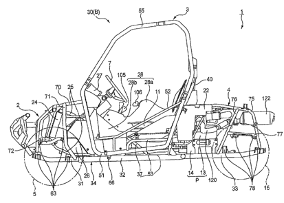
As illustrated in Figs. 1 to 3, a vehicle 1 according to the embodiment
includes a
vehicle body frame 30 which includes a front frame portion 2, a center frame
portion 3, and a rear frame portion 4 so as to constitute a vehicle body B. A
front-wheel suspension system (not illustrated) which suspends left and right
front wheels 5 is attached to the front frame portion 2. In addition, a front-
wheel
drive system including a front differential gear unit 81, front drive shafts
82, and
the like; steering members (including a steering shaft 6 and a steering wheel
7
attached to an upper end of the steering shaft 6) for steering the front
wheels 5;
and the like are supported on the front frame portion 2.
A pair of occupant seats 11, constituting a driver's seat 9 and a passenger
seat 10
arranged side by side in a vehicle width direction, are attached to the center
frame portion 3, so that a space for occupants is formed. A fuel tank 12 is
disposed in a space below the passenger seat 10. A front propeller shaft 83
coupling a power unit P and a front differential gear unit 81 is disposed
between
the driver's seat 9 and the passenger seat 10.
A rear-wheel suspension system (not illustrated) which suspends left and right
rear wheels 15 is attached to the rear frame portion 4. In addition, a rear-
wheel
drive system including, for example, a rear propeller shaft 86, a rear
differential
gear unit 84, rear drive shafts 85; and the like are supported on the rear
frame
portion 4 in addition to the power unit P including an internal combustion
engine 13 and a transmission 14.
As illustrated in Fig. 3, the power unit P supported on the rear frame portion
4 is
laid out vertically in such a manner that a crankshaft 16 of the internal
combustion engine 13 is directed in a front-rear direction of the vehicle
body. An
output shaft 80 to which a driving force is transmitted from the crankshaft 16
is
disposed substantially on a center line CL of the vehicle body. The output
shaft
80 is coupled at a front end thereof to the front propeller shaft 83 and is
coupled
at a rear end thereof to the rear propeller shaft 86.
WH-13533/cs
CA 02673393 2009-07-21
-8-
The rear propeller shaft 86 is connected to the rear differential gear unit 84
disposed substantially on the center line CL of the vehicle body. The driving
force of the internal combustion engine 13 is transmitted to the left and
right rear
wheels 15 via the rear propeller shaft 86, the rear differential gear unit 84,
and
then the rear drive shafts 85 connected to the rear differential gear unit 84.
The front propeller shaft 83 is provided with a reduction gear 90 at an
intermediate portion of the front propeller shaft 83. The front propeller
shaft 83
is constituted of a first propeller shaft 87 and a second propeller shaft 88.
The
first propeller shaft 87 is disposed at the rear of the reduction gear 90,
while the
second propeller shaft 88 is disposed at the front of the reduction gear 90.
The
reduction gear 90 transmits the rotational force of the first propeller shaft
87 to
the second propeller shaft 88 while converting the rotational direction of the
first
propeller shaft 87 into the reverse direction in order to rotate the front
wheels 5
and the rear wheels 15 in the same direction. Accordingly, the driving force
of
the internal combustion engine 13 is transmitted to the left and right front
wheels
5 via the first propeller shaft 87, the reduction gear 90, the second
propeller shaft
88, the front differential gear unit 81, and then the front drive shafts 82
connected
to the front differential gear unit 81.
As illustrated in an enlarged manner in Fig. 8, a throttle valve unit 19 is
connected to a rear portion of a cylinder head 18 of the internal combustion
engine 13 via an intake manifold 20. An exhaust pipe 120, which will be
described later, is connected to a front portion of the cylinder head 18. An
air
cleaner 110 including first and second air cleaner chambers 111 and 112, which
will be described later, is connected to a rear portion of the throttle valve
unit 19
via a connecting tube 117. Moreover, a fuel supply pipe 21 and a wire harness
23
are connected to the throttle valve unit 19. The fuel supply pipe 21 extends
from
the fuel tank 12. The wire harness 23 is arranged to extend from a battery
case 22
including the battery case 22, an ECU 26, and the like.
Moreover, as illustrated in Figs. 2 and 4, a radiator 24 disposed in the front
frame
portion 2 is connected to the internal combustion engine 13 via two water
supply
WH-13533/cs
CA 02673393 2009-07-21
-9-
pipes 25. Thus, cooling water for cooling the internal combustion engine 13
circulates between the radiator 24 and the internal combustion engine 13
through
the water supply pipes 25.
Note that, in Fig. 1, reference numeral 26 denotes a front cover; reference
numeral 27 denotes an instrument panel; reference numeral 28 denotes a center
console cover including a center cover member 28a as well as a pair of left
and
right cover members 28b.
As illustrated in Figs. 4 and 5, the vehicle body frame 30 includes a pair of
lower
frames 34 disposed respectively in left and right lower portions of the
vehicle
body B and extending in the front-rear direction. Each of the lower frames 34
forms a front lower frame 31, a center lower frame 32, and a rear lower frame
33.
In the front frame portion 2, a pair of left and right front upper frames 70
extend
upward from front ends of the respective front lower frames 31, further extend
rearward, and then are joined to a front upper cross-member 44. In this
manner,
the left and right front upper frames 70 cover a front portion of the vehicle
body
B from above. The front lower frames 31 and the front upper frames 70 are
coupled to one another by a square U-shaped frame 71.
In addition, rising portions of the square U-shaped frame 71 are coupled
respectively to rising portions of the front upper frames 70 by front-
suspension
support pipes 72 each formed into a substantially L-shape. Two brackets 63 are
fixed onto each of the front lower frames 31 and the front-suspension support
pipes 72, and the front-wheel suspension system is swingably disposed on the
brackets 63. The front-wheel suspension system rotatably suspends the left and
right front wheels 5.
On the other hand, in the rear frame portion 4, a pair of left and right rear
upper
frames 75 extend upward from rear ends of the rear lower frames 33, thereafter
are bent to extend frontward in such a manner as to cover the power unit P
including the internal combustion engine 13, and then are joined respectively
to a
pair of center upright frames 40. The center upright frames 40 extend upward
WH-13533/cs
CA 02673393 2009-07-21
-10-
from portions, behind the occupant seats 11, of the respective center lower
frames 32. Horizontal portions of the rear upper frames 75 are vertically
connected to the rear lower frames 33 respectively by rear upright frames 76,
each of which is inclined frontward while extending downward. Moreover, the
rear upright frames 76 are connected respectively to perpendicular portions of
the corresponding rear upper frames 75 respectively by rear-suspension support
pipes 77.
Two brackets 78 are fixed respectively onto front and rear portions of each of
the
rear lower frames 33 and the rear-suspension support pipes 77. The rear-wheel
suspension system is swingably disposed on the four brackets 78 in total. The
rear-wheel suspension system suspends the left and right rear wheels 15 in a
manner that the rear wheels 15 are rotatable.
In the center frame portion 3, a pair of left and right side frames 51, which
extend
in the front-rear direction, are disposed respectively outside the center
lower
frames 32 in the vehicle width direction. The side frames 51 are joined to the
respective lower frames 34 by connecting pipes 66 and connecting pipes 67. The
connecting pipes 66 are connected to front portions of the respective center
lower
frames 32, while the connecting pipes 67 are connected to intermediate
portions
of the respective center upright frames 40.
Each of the side frames 51 includes a front rising portion 51a, a rear rising
portion 51b, and a horizontal portion 51c joining the front and rear rising
portions 51a and 51b, and is thus formed in a substantially square U-shape,
which is convex downward.
In each of the substantially square U-shaped side frames 51, the front rising
portion 51a and the rear rising portion 51b are coupled to each other by a
side
pipe 52 in the front-rear direction. End portions of the respective front
rising
portions 51a of the pair of side frames 51 are coupled to each other by the
front
upper cross-member 44 in the vehicle width direction. Middle portions of each
rear rising portion 51b and the corresponding horizontal portion 51c are
coupled
to each other by a seat supporting pipe 53 having a substantially,L shape.
WH-13533/cs
CA 02673393 2009-07-21
-11-
A pair of side upper frames 55, each formed into a substantially square U
shape,
are each connected to the front rising portion 51a and the rear rising portion
51b
of a corresponding one of the pair of side frames 51 in such a manner that the
side upper frame 55 is convex upward. The pair of side upper frames 55 are
coupled to each other in the vehicle width direction by: a first upper cross-
member 54, to which the pair of center upright frames 40 are joined at upper
end
portions thereof; two roof cross-members 56 and 57; and a cross-member 58 for
headrest, which is joined at a middle portion thereof to the first upper cross-
member 54.
A first seat cross-member 61 is laid between the pair of seat supporting pipes
53
with brackets therebetween. In addition, a pair of second seat cross-members
62
are joined to the rear rising portions 51b of the respective side frames 51
with
brackets therebetween. The second seat cross-members 62 are joined to a rear
cross-member 64 which connects the pair of center upright frames 40 to each
other at portions lower than the middle portions thereof. The first and second
seat cross-members 61 and 62 as well as coupling frames 65, which couple the
respective second seat cross-members 62 to the first seat cross-member 61 in
the
front-rear direction, constitute seat frames. Seat pipes 60 (refer to Fig. 9)
for the
driver's seat 9 and the passenger seat 10 are attached to the seat frames.
In addition, in the center frame portion 3, a center pipe 35 is provided. The
center pipe 35 passes between the driver's seat 9 and the passenger seat 10
and is
arranged above the lower frames 34 to extend in the front-rear direction
substantially on the center line CL of the vehicle body. Accordingly, the
center
frame portion 3 has a structure in which the center pipe 35 and the pair of
lower
frames 34 are disposed respectively on the upper and lower sides in the center
portion in the vehicle width direction, and the side pipe 52 and the side
frame 51
are disposed on the upper and lower sides in each of the side portions. This
structure makes it possible to improve the rigidity of the center frame
portion 3
as well as to achieve a low floor and a low center of gravity.
WH-13533/cs
CA 02673393 2009-07-21
-12-
As illustrated in an enlarged manner also in Fig. 7, the center pipe 35
includes an
upper center pipe 36, a down center pipe 37, an upright center pipe 38, and a
front center pipe 39. These members 36, 37, 38, and 39 are joined together at
a
joint point J located in front of the occupant seats 11.
The upper center pipe 36 extends frontward while being joined at one end
thereof to a center portion of a rear upper cross-member 41 which couples the
pair of center upright frames 40 to each other. The down center pipe 37
extends
upward and frontward while being joined at one end thereof to a center portion
of a rear lower cross-member 42 which is laid between the center lower frames
32
at a position below the occupant seats 11.
The upright center pipe 38 extends rearward and upward while being joined at
one end thereof to a center portion of a front lower cross-member 43 which is
laid between the center lower frames 32 at a position in front of the occupant
seats 11. The front center pipe 39 is- a pipe member that is formed into a
substantially V shape with two branches extending frontward respectively to
the
left and right from the joint point J as the base point. An end portion of
each of
the left and right branches is joined to the front upper cross-member 44 in a
vicinity of the joint portion of a corresponding one of the front upper frames
70
to the front upper cross-member 44.
Note that, in the embodiment, the pair of center upright frames 40 and the
rear
upper cross-member 41 are frames, which constitute, behind the occupant seats,
the vehicle body frame, of the present invention; the center lower frames 32
and
the rear lower cross-member 42 are frames constituting a lower frame of the
present invention; and the front upper frames 70 and the front upper cross-
member 44 are frames constituting, in front of the occupant seats, the vehicle
body frame.
On the center pipe 35 constituted as described above, a shift lever 105 is
attached
to a portion above a vicinity of the joint point J having increased rigidity,
and a
side-brake lever 106 is attached to a portion above an intermediate portion of
the
upper center pipe 36. Note that, the steering shaft 6, which is a steering
member,
WH-13533/cs
CA 02673393 2009-07-21
-13-
is attached to the front upper cross-member 44 with a subframe 107 interposed
therebetween. Wires extend from the shift lever 105, the side-brake lever 106,
and the steering shaft 6, as well as from foot controls 91, such as a brake
pedal
and an acceleration pedal, disposed on the driver's seat 9 side, and the like.
These extending wires are gathered in an electric connection box 103, and then
bundled into a single wire harness 104, which is eventually connected to the
battery case 22 provided behind the driver's seat 9.
In addition, as illustrated in Figs. 2, 3 and 7, the first propeller shaft 87
is located
below and along the center pipe 35 substantially on the center line CL of the
vehicle body. The first propeller shaft 87 is disposed also in such a manner
as to
overlap the fuel tank 12 in a side view, in other words, in such a manner that
the
first propeller shaft 87 and the fuel tank 12 are arranged side by side in the
vehicle width direction. The second propeller shaft 88 connected to the
reduction gear 90 is disposed offset toward the passenger seat 10 in the
vehicle
width direction with respect to the first propeller shaft 87. Moreover, the
second
propeller shaft 88 is coupled, on the passenger seat 10 side, to the front
differential gear unit 81 disposed substantially on the center line CL of the
vehicle body above the front lower frames 31.
As described above, since the front propeller shaft 83 is arranged
substantially
along the center pipe 35, the torsion in the vehicle 1 is unlikely to act on
the front
propeller shaft 83. In addition, since the second propeller shaft 88 is
disposed
offset toward the passenger seat 10 in the vehicle width direction, a large
space
for occupants can be secured even with the lowered floor, and also, the
flexibility
in layout of the foot controls 91 is improved, so that the foot controls 91
can be
disposed at positions where the foot controls 91 are easily operated.
Moreover, the reduction gear 90 is located in front of the pair of occupant
seats
11, and also behind the foot controls 91, such as the brake pedal and
acceleration
pedal, disposed on the driver's seat 9 side, and is disposed between the down
center pipe 37 and the upright center pipe 38.
WH-13533/cs
CA 02673393 2009-07-21
-14-
The two water supply pipes 25, which connect the radiator 24 and the internal
combustion engine 13, as well as the wire harness 104, which electrically
connects
the electric connection box 103 and the battery case 22, are also disposed
offset
toward the passenger seat 10 side in the vehicle width direction, partially in
a
region in front of the upright center pipe 38, as in the case of the front
propeller
shaft 83.
Accordingly, the center console cover 28 provided between the driver's seat 9
and the passenger seat 10 houses the center pipe 35, the front propeller shaft
83,
the reduction gear 90, the water supply pipes 25, the wire harness 104, the
shift
lever 105, and the side brake lever 106, while a front portion of the center
console
cover 28 is offset toward the passenger seat 10 side.
With this arrangement, the water supply pipes 25 and the wire harness 104 are
compactly arranged by utilizing the dead space. As a result, a large space for
occupants can be secured, and also, the flexibility in layout of the foot
controls 91
is improved, so that the foot controls 91 can be disposed at positions where
the
foot controls 91 are easily operated.
Further, while the vehicle body frame 30 is formed in a bilaterally
symmetrical
arrangement, the front differential gear unit 81, the reduction gear 90, the
internal combustion engine 13, the rear differential gear unit 84, and the
like,
which are major heavy components, are disposed substantially on the center
line
CL of the vehicle body. As a result, a favorable weight balance between the
left
and right sides is achieved to increase the stability of the vehicle 1.
As illustrated in Figs. 8 to 10, the air cleaner 110, which is an air-intake
device, is
disposed behind the passenger seat 10 on the right side of the internal
combustion engine 13, and includes the first air cleaner chamber 111 and the
second air cleaner chamber 112.
A snorkel 113 is connected to the first air cleaner chamber 111 via a duct
attached
to an outer side surface of the first air cleaner chamber 111 in the vehicle
width
direction. The snorkel 113 is disposed behind the passenger seat 10 and has a
WH-13533/cs
CA 02673393 2009-07-21
-15-
cover 114 for covering its opening. The first air cleaner chamber 111 and the
second air cleaner chamber 112 face each other in the vehicle width direction
with the rear upright frame 76 on the corresponding side being partially
sandwiched therebetween, and communicate with each other via a coupling tube
116. In addition, the second air cleaner chamber 112 is connected to the
internal
combustion engine 13 via the connecting tube 117.
Accordingly, the first air cleaner chamber 111 is disposed outside the
corresponding rear upright frame 76 in the vehicle width direction, and the
second air cleaner chamber 112 is disposed inside the rear upright frame 76 in
the vehicle width direction. In addition, an air cleaner element 115 for
removing
dust in the air is housed in the first air cleaner chamber 111.
In the air cleaner 110 as described above, external air is introduced from the
snorkel 113; then dust in the air thus introduced is removed by the air
cleaner
element 115 in the first air cleaner chamber 111; the purified air is guided
to the
second air cleaner chamber 112 through the coupling tube 116, and thereafter,
is
supplied to the internal combustion engine 13 from the connecting tube 117.
Since the air cleaner 110 is constituted of: the first air cleaner chamber 111
disposed outward of the corresponding lower frame 34 in the vehicle width
direction and the second air cleaner chamber 112 disposed inward thereof in
the
vehicle width direction. Accordingly, the air cleaner 110 having a large
capacity
can be compactly disposed in a narrow space surrounded by the frames. In
addition, since the first air cleaner chamber 111 is disposed outward of the
corresponding rear upright frame 76 in the vehicle width direction, a large
space
for maintenance of the air cleaner 110 can be secured. For this reason, a
maintenance operation can be easily performed on the air cleaner 110, that is,
the
air cleaner 110 has an excellent maintainability.
It should be noted that the above-described effect can be obtained even when
the
first and second cleaner chambers 111 and 112 are disposed to sandwich a part
of
the corresponding lower frame 34 or of the corresponding rear upper frame 75
WH-13533/cs
CA 02673393 2009-07-21
-16-
instead of the rear upright frame 76, in accordance with the position where
these
chambers 111 and 112 are attached.
Moreover, as illustrated in Figs. 8 and 11, the exhaust pipe 120 connected to
the
front portion of the cylinder head 18 first extends frontward, thereafter
turns
around and extends rearward, is further bent at substantially 90 , and
linearly
extends to the outside of the vehicle body while being inclined downward with
respect to the horizontal plane. Moreover, after reaching a region behind the
driver's seat 9 in the vehicle width direction, the exhaust pipe 120 is bent
to the
inside of the vehicle body and linearly extends back substantially onto the
center
line CL of the vehicle body while being inclined upward, and is then connected
to a muffler 122 disposed to extend in the front-rear direction substantially
on
the center line CL of the vehicle body in the rear frame portion 4. With this
arrangement, an outermost extending portion 121 of the exhaust pipe 120
extends to a region inside a rearward extension line of the corresponding side
frame 51 in the vehicle width direction and outside the corresponding rear
upper
frame 75 in the vehicle width direction.
Accordingly, a required length can be secured for the exhaust pipe 120 even
in,
for example, the vehicle 1 having the lowered floor, in which the space in the
rear
frame portion 4 is limited with the internal combustion engine 13 disposed
behind the occupant seats 11. Moreover, having many straight portions, the
exhaust pipe 120 can be easily processed, so that the number of assembly
processes can be reduced and that the manufacturing costs thus can be
suppressed.
The outermost extending portion 121 of the exhaust pipe 120 extends to the
region inside the rearward extension line of the corresponding side frame 51
in
the vehicle width direction and outside the corresponding rear upper frame 75
in
the vehicle width direction. With this arrangement, the exhaust pipe 120 is
protected while the length of the exhaust pipe 120 is sufficiently secured.
In addition, the exhaust pipe 120 extends back substantially onto the center
line
CL of the vehicle body within a region in front of the rear upright frames 76.
WH-13533/cs
CA 02673393 2009-07-21
-17-
This makes it possible to securely prevent an interference of the exhaust pipe
120
with the rear-wheel suspension system disposed rearward of the rear upright
frames 76.
As described above, according to the frame structure for a vehicle of the
embodiment, the center pipe 35 extends between the driver's seat 9 and the
passenger seat 10, and is arranged in the front-rear direction substantially
on the
center line CL of the vehicle body in the vehicle body frame 30. This
arrangement makes it possible to improve the rigidity of the vehicle body
frame
30.
In addition, the frame structure for a vehicle includes the pair of left and
right
side frames 51 extending in the front-rear direction respectively outside the
lower frames 34 in the vehicle width direction. The front and rear portions of
each side frame 51 are connected to each other by the side pipe 52, and the
center
pipe 35 is arranged above the lower frames 34 to extend in the front-rear
direction substantially on the center line CL of the vehicle body.
Accordingly,
the rigidity of the side portions of the vehicle body frame 30 is secured by
the
pair of side frames 51 and the pair of side pipes 52 disposed respectively on
the
upper and lower sides, while the rigidity of the center portion of the vehicle
body frame 30 is secured by the center pipe 35 and the pair of lower frames 34
disposed respectively on the upper and lower sides. With this structure, the
height of the occupant seats and the floor height can be lowered while the
rigidity of the vehicle body frame 30 is sufficiently maintained, so that a
low
floor and a low center of gravity can be achieved.
Furthermore, the center pipe 35 includes the upper center pipe 36, the down
center pipe 37, the upright center pipe 38, and the front center pipe 39.
These
members 36, 37, 38, and 39 are joined together at the joint point J located in
front
of the occupant seats 11. Accordingly, this center pipe structure makes it
possible to improve the rigidity of the vehicle body.
In addition, the frame structure for a vehicle includes the pair of left and
right
front upper frames 70 extending from front ends of the respective front lower
WH-13533/cs
CA 02673393 2009-07-21
-18-
frames 31 so as to cover the front portion of the vehicle body B from above.
Moreover, the front center pipe 39 formed into the left and right branches is
joined to the front upper cross-member 44 in the vicinities of the respective
joint
portions of the front upper frames 70 to the front upper cross-member 44. This
makes it possible to further improve the rigidity of the vehicle body B, and
also
to reduce a bending force acting on the front upper cross-member 44.
In addition, since the front propeller shaft 83 which transmits the driving
force of
the internal combustion engine 13 to the front-wheel drive system is arranged
substantially along the center pipe 35, the torsion in the vehicle body B is
unlikely to act on the front propeller shaft 83. Moreover, the front propeller
shaft
83 can be disposed by utilizing the dead space below the center pipe 35, which
enables a compact layout, so that a large space for occupants can be secured.
Furthermore, the reduction gear 90, which converts the rotational direction of
the
front propeller shaft 83 into the reverse direction, is located in front of
the
occupant seats 11, and also behind the foot controls 91, and is disposed
between
the down center pipe 37 and the upright center pipe 38. Accordingly, the
reduction gear 90 can be disposed in the dead space where the rigidity of the
vehicle body is high. As a result, it is possible to protect the reduction
gear 90,
and to enable a compact layout, which secures a large space for occupants.
In addition, since the center pipe 35 is provided in the center frame portion
3
having the space for occupants therein, the rigidity of the center frame
portion 3
can be improved.
In addition, the radiator 24 is arranged in the front frame portion 2, and the
internal combustion engine 13 is arranged in the rear frame portion 4. In this
arrangement, the water supply pipes 25 connecting the radiator 24 and the
internal combustion engine 13 are arranged substantially along the center pipe
35
in such a manner as to extend in a region on the passenger seat 10 side of the
upright center pipe 38 in front of the upright center pipe 38. This
arrangement
allows the water supply pipes 25 to be arranged in the dead space with a high
rigidity of the vehicle body. As a result, it is possible to protect the water
supply
WH-13533/cs
CA 02673393 2009-07-21
-19-
pipes 25, and to enable a compact layout, which secures a large space for
occupants.
Moreover, since the shift lever 105 is disposed in a vicinity of the joint
point J of
the members 36, 37, 38, and 39 constituting the center pipe 35, the shift
lever 105
can be provided at a position where the rigidity of the vehicle body is high
and
where the driver can easily operate the shift lever 105, with no provision of
any
separate support bracket dedicated to the shift lever 105.
Furthermore, since the side brake lever 106 is disposed on the upper center
pipe
36, the side brake lever 106 can also be provided at a position where the
driver
can easily operate the side brake lever 106, with no provision of any separate
support bracket dedicated to the side brake lever 106.
Moreover, the center console cover 28 provided between the driver's seat 9 and
the passenger seat 10 houses the center pipe 35, the front propeller shaft 83,
the
reduction gear 90, the water supply pipes 25, the wire harness 104, the shift
lever
105, and the side brake lever 106. Accordingly, the above members can be
gathered in the center of the vehicle body, and also covered with the center
console cover 28. As a result, the external appearance is improved and also a
large space for occupants is secured.
It should be noted that the present invention is not limited to the above-
described embodiment, and modification, improvement, and the like may be
made thereon as appropriate. For example, although the present invention has
been described so far as being applied to an MUV (multi utility vehicle), the
present invention is not limited to this but may be applied to any type of
vehicle
having four or more wheels in the same manner.
WH-13533/cs