Note: Descriptions are shown in the official language in which they were submitted.
CA 02673405 2014-06-17
31460-5
1
NOSE-DILATING DEVICE
Technical Field
The present invention relates to an internal nose-dilating device.
Technical Background
Breathing through the noseduring sleep is highly advantageous
compared with breathing through the mouth. When breathing through your
= mouth the saliva secretion decreases and the mucous membranes become
dry. This provides a breeding ground for bacteria and causes dental
problems, or an increase thereof, since there is no longer enough fresh saliva
for efficacious rinsing. A further aspect of breathing through the mouth is
that
the teeth are not sufficiently supported and, when the jaws are being
separated, thus start to grow at an angle, as there is no resistance.
Breathing through the mouth increases the risk of snoring, since
anatomically the throat becomes narrower and the airway smaller as a result
of the lower jaw frequently dropping. This constriction of the throat often
causes snoring and abnormal breathing. A narrow airway means that you
must breathe harder to get enough oxygen, the result being even more
snoring sounds.
To reduce or completely eliminate the snorings, snoring guards
designed to reposition the lower jaw forward can be used, the guards being
positioned in the mouth and retained by an occlusal hold. A drawback of
these guards, however, is that they do not bring the jaws tightly together,
which means that people with restricted nasal meatuses will tend to open
their mouth to breath and, with the mouth open, the effect of snoring guards
designed to reposition the lower jaw forward is lost. To improve the situation
of these people, the snoring guard designed to reposition the lower jaw
forward can be combined with a nose-dilating device, i.e. means arranged
outside or inside the nose to dilate the nostrils.
Some people may have a partly deformed nose, which results in an
inaccurate air flow and when the person breathes heavily through the nose
CA 02673405 2009-06-29
WO 2008/077604 PCT/EP2007/011321
2
the nasal walls are simply sucked together, thus obstructing the passage of
air. This may also be important, for example, when practicing sports, in which
case an optimal air intake is desired.
There are currently a number of methods and means for creating and
maintaining a satisfactory passage of air through the nose, for instance by
means of external nose-dilating devices, such as nose adhesive strips, or
internal nose dilating means, such as plastic springs provided between the
nostrils to dilate the nasal openings, and decongestants, such as nose sprays
or nose drops.
US 6,004,342 discloses an internal nose-dilating device, which
comprises a pair of hollow, cylindrical members, which are made of an
elastomeric material and have the shape of a nostril and are designed to be
worn inside the nose, a handle portion connecting the two nasal inserts. The
drawback of this device is that it cannot be adjusted to different nose shapes
or different dilating needs.
WO 8803788 discloses a nose-dilating device in the form of two end
portions that are interconnected in a resilient manner, i.e. like a spring-
resembling plastic wing, which is inserted into both nostrils, whereby the
rigidity of the resilient material causes the front part of the nostrils to
dilate. A
considerable drawback is here that a large part of the device protrudes from
the nose. Due to the strong biasing force, any contact with the device, for
instance when touching the pillow or poking it directly, may dislocate the
wings, the rigidity of the material thereby causing the plastic wing to fly
out of
the nose. Accordingly with such a strong biasing force, the product is
sensitive to outer influence.
US 5,895,409 discloses an internal nose-dilating device in the form of
cylindrical convex tubes, which are inserted into the nose to dilate the
nostrils
and which are connected by means of a larger external portion. The tubes
consist of an open framework having an interior portion and an exterior
portion and a plurality of interconnected elongate members, which members
extend between the interior and exterior portions and at least one of which is
convex. The device described in this document is intended for use in
connection with strenuous physical exercise and the administration of
CA 02673405 2009-06-29
WO 2008/077604 PCT/EP2007/011321
3
anaesthetics. Such devices are often rigid and clearly visible and, above all,
rarely adapted to the anatomy of the nose and its different cavities. They are
often too long and too bulky and therefore less comfortable and efficacious,
since their straight lines make it difficult to keep them positioned in the
nose.
Furthermore, due to their design they do not fit all types of noses. The air
flow
obtained when using a completely round insert is not optimal, since a
significant part of the air has to pass along the side, its passage being, in
fact,
partly obstructed by the device. Due to the exterior larger portion there is
also
an increased risk of the device flying out of the nose when touched.
US 2003150449 discloses a nasal strip, which is attached to the nose
by means of adhesive ends for the purpose of nasal dilation. The drawback of
devices of this kind is that they are clearly visible and that thorough
cleaning
of the nose to remove grease is required before attaching them. In many
cases, such nasal strips can be used only once, thus generating a significant
yearly cost. There is also a risk of the person wearing it being affected by
the
adhesive. When practicing sports, drops of perspiration form, which may
reduce the strength of the strip adhesive. Often, the adhesive used is strong,
which implies time-consuming cleaning. Beauty creams cannot be used,
which some people consider to be a disadvantage.
There is hence a need for a nose-dilating device which dilates the
nostrils to obtain an optimal air intake when sleeping or practicing sports,
which device may easily be adjusted to fit all types of nostrils, which due to
ethnical origin or injury may be of different shapes, and which is firmly
positioned in the nose without being affected when touched. Furthermore, the
nasal dilation should be individually adjustable for each nostril. The nose-
dilating device should also be discreet and shaped in a suitable manner to fit
the anatomy of the nose. It should be positioned inside the nose and expand
entirely individually from a centre of its own, which makes each insert
independent of the other. Moreover, the nose-dilating device should be easy
to clean and adapted for repeated use.
CA 02673405 2009-06-29
WO 2008/077604 PCT/EP2007/011321
4
Summary of the Invention
It is an object of the present disclosure, to provide a nose-dilating
device, which eliminates or alleviates at least some of the disadvantages of
the prior art.
According to a first aspect, there is provided an internal nose-dilating
device comprising two conical inserts, which each have four walls and two
openings, a small opening, which during use is oriented inwards towards the
nasal cavity and a large opening, which is oriented out from the nose, the
inserts being connected by means of a connecting member, which during use
is the only part that remains on the outside of the nose, characterised in
that
the four walls of the inserts are convex at their central portions and
provided
with a substantially horizontal recess, the recess being arranged along the
four walls of the inserts and extending at least partly along the
circumference
on the outside thereof to form a bulge in the four walls of the inserts, and
that
the inserts have at least four apertures, and that a reinforced portion is
provided along the rounded edge of the small opening, thereby allowing the
inserts to be turned inside out.
By "substantially horizontal" is meant that the recess during use of the
insert is substantially horizontal or even horizontal.
By way of these features, a bulge in the four walls of the inserts is
achieved when the inserts are compressed by applying a light pressure from
above and from below, the compression being achieved by the wearer
squeezing the insert with his fingers. When inserting the nose-dilating
device,
the bulge or out-turned fold causes cause an expansion of the nostril walls.
After compression, the nose-dilating device retains its expanded shape. Thus,
an individually adapted nasal dilation can be obtained by varying the
compression of the inserts, which may be important, for instance, if the nose
is only partly deformed, in which case a greater expansion is required for one
nostril than for the other. During use, the outer convex surface abuts against
the inside of the nostril, thereby expanding the nasal passage outwards.
Consequently, the insert is designed to lean against the inside of the nostril
and the force required to prevent the nasal walls from collapsing is minimal,
CA 02673405 2009-06-29
WO 2008/077604 PCT/EP2007/011321
the inserts having thus a centripetal effect, thereby preventing the nose
dilating device from being pushed out of the nostrils.
This configuration optimises nasal dilation and thus the breathing
through the nose, with respect to various degrees of nasal dilation and with
5 respect to different nostril shapes.
By the inserts having four apertures and a reinforced portion there is
provided a way of allowing the inserts to be turned inside out. When turned
inside out, the inserts will have a rounder shape because of the inner
tensions
in the nose-dilating device, which further improves the nose-dilating effect
and
also ensures a rounder fit to the nostrils. It is not necessary to turn both
inserts inside out; instead one insert at a time can be turned to obtain a
greater or smaller dilation of the nostrils. In addition, the reinforced edge
along the small opening is rounded so as to be more comfortable for the
wearer during insertion and use of the nose-dilating device, by the soft
tissue
and mucous membranes being protected from chafing.
By the connecting member being the only part of the device which is
located outside, the risk of any external influence on the nose-dilating
device
is minimized.
In one embodiment, the inserts may suitably be kidney-shaped, to
better fit the nasal cavity.
In one embodiment, the four openings may, be arranged at the corners
of the inserts. The apertures may also be arranged at the long sides of the
inserts or, according to one embodiment, at the short sides of the inserts.
The
arrangement of the apertures will be depending on the shape of the inserts.
In one embodiment, the nose-dilating device may be provided with a
decongestant.
By "decongestant" is meant a substance such as eucalyptus or
menthol, to alleviate the problems associated with nasal congestion in case of
a cold or allergies. The decongestant is suitably applied to the inside of the
nose-dilating device to avoid direct contact with the mucous membranes.
According to one embodiment the nose-dilating device may be made of
an elastic material.
CA 02673405 2009-06-29
WO 2008/077604 PCT/EP2007/011321
6
Examples of such material may be, but is not limited to, plastic
materials, rubber materials, silicone materials or combinations thereof, the
central portion may, for example, be made of a rigid material and the rest of
a
soft material. Preferably, the material is soft and comfortable for the
wearer.
The material may also suitably be allergy-tested.
The connecting member may, according to one embodiment, be rigid
and substantially U-shaped.
By the rigid and substantially U-shaped connecting member there is
provided means for ensuring that the inserts are not inserted too far in the
nostrils and to centre the inserts in the nose. The rigidity of the connecting
member may also aid in the adjustment of the nose-dilating device once it has
been inserted into the nose of the wearer.
According to a second aspect of the present disclosure there is
provided a method for changing the size of a nose-dilating device, according
to the first aspect, which comprise compressing the inserts, by applying an
axial force, by the wearer squeezing the insert with his fingers.
By "axial force" is meant that the wearer squeezes the insert at both
the small and large opening and thereby compresses the inserts.
By this method there is provided an easy way of changing the size of
the inserts. The compression will contribute to the bulging of the walls of
the
inserts, and hence to a different size of the insert.
According to a third aspect there is provided method for using a nose-
dilating device, according to the second aspect, and inserting the inserts
into
the nostrils of the wearer.
According to a fourth aspect there is provided a method for changing
the size of a nose-dilating device, according to the first aspect, comprising
turning at least one insert inside out.
By turning at least one insert inside out a more rounded shape of the
insert is achieved, which may fit more properly in a nostril with a more
rounded shape.
According to a fifth aspect there is provide a method for using a nose-
dilating device, according to the fourth aspect, and inserting the inserts
into
the nose of the wearer.
CA 02673405 2009-06-29
WO 2008/077604 PCT/EP2007/011321
7
By the changing of the size prior to the insertion into the nose a more
proper fit in the nostril may be provided.
The methods, according to the third and fifth aspect, may further
comprise centring the inserts in the nose by adjusting the angle which the
device has in the nose. The insert may be centred by moving the connecting
member.
By adjusting the position of the inserts, when they have been inserted
into the nostrils of the wearer, there is provided a way obtaining an optimal
angle of the nose-dilating device when positioned in the nose.
According to a sixth aspect of the present solution there is provided a
method for changing the size of a nose-dilating device, which comprise
heating up the device, to a temperature where the material softens, and
compressing the inserts, by applying an axial force, by the wearer squeezing
the insert with his fingers.
By "axial force" is meant that the wearer squeezes the insert at both
the small and large opening, thereby compressing it.
According to a seventh aspect of the present solution there is provided
a method for using a nose-dilating device, according to the sixth aspect, and
inserting the inserts into the nostrils of the wearer.
According to an eight aspect there is provided a method for changing
the size of a nose-dilating device, which comprise heating up the device, to a
temperature where the material softens, and turning at least one insert inside
out.
According to a ninth aspect there is provided method for using a nose-
dilating device, according to the eight aspect, and inserting the inserts into
the
nostrils of the wearer.
By heating up the device before compressing the inserts and/or turning
the inserts inside out there may be provided an even better way of adjusting
the size of the inserts, since the material has been made softer and hence
more pliable by the heating.
By the changing of the size before insertion into the nose a more
proper fit in the nostril may be provided.
CA 02673405 2015-02-02
= 31460-5
8
The methods according to the seventh and ninth aspects, further
comprising centring the inserts in the nose by adjusting the angle which the
device
has in the nose. The insert may be centred by moving the connecting member.
According to a further aspect there is provided an internal nose-dilating
device, comprising two inserts, which each have four walls and two openings: a
small
opening, which during use is orientated inwards towards the nasal cavity, and
a large
opening, which is orientated out from the nose, the inserts being connected by
means
of a connecting member, which during use is the only part that remains on the
outside of the nose, the inserts having at least four apertures; wherein the
four walls
of the inserts are convex at their central portions and provided with a recess
which,
during use, is substantially horizontal, the recess being arranged along the
four walls
of the inserts and extending at least partly along the circumference on the
outside
thereof to form a bulge in the four walls of the inserts; and wherein a
reinforced
portion is provided along a rounded edge of the small opening, thereby
allowing the
inserts to be turned inside out.
By adjusting the position of the inserts, when they have been inserted
into the nostrils of the wearer, there is provided a way obtaining an optimal
angle of
the nose-dilating device when positioned in the nose.
Description of the Drawings
Embodiments of the present solution will now be described, by way of
example, with reference to the accompanying schematic drawings.
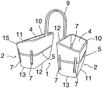
Fig. 1 is a schematic cross sectional view of a nose-dilating device.
Fig. 2 is a schematic perspective view over the small openings.
Fig. 3 is a schematic perspective view over the large openings.
CA 02673405 2015-02-02
31460-5
8a
Fig. 4 is a schematic cross sectional view of both inserts turned inside
out.
Fig. 5 is a schematic perspective view of a nose-dilating device with one
insert turned inside out.
Fig. 6 is a schematic perspective view of one embodiment of the
present solution.
Description of Embodiments
Figs 1-5 illustrates a nose-dilating device 1 comprising two inserts 2,
which have recesses 6 through which air flows when the inserts 2 are
positioned in
the nose.
Figs 2 and 3 illustrate that the insert 2 has two short sides 10, 13 and
two long sides 11, 12 and two openings: a small opening 3, which during use of
the
nose-dilating device is oriented towards the inner cavity of the wearer's
nose, and a
large opening 4, which during use is oriented out of the nose.
Figs 2 and 3 illustrates that the openings 3 and 4 may be substantially
oval-shaped to fit the shape of the nostril.
Fig. 1 illustrate that the insert 2, may substantially be conical.
Fig. 1 illustrate that the walls 10, 11, 12, 13 of the insert are convex at
their central portion with a convex surface 16 on the outside of the inserts
and a
concave surface 17 on the inside thereof.
CA 02673405 2009-06-29
WO 2008/077604 PCT/EP2007/011321
9
Fig. 1 illustrate that the inserts 2 are interconnected by means of a
connecting member 9. The connecting member may, according to one
embodiment be substantially in the form of a U-shaped strip. The connecting
member 9 may also consist of two parts, one of which is attached to the long
side 12 adjacent the large opening 4.
The inserts 2 and the connecting member 9 may suitably be formed in
one piece. The rigidity and U-shape of the connecting member 9 are also
intended to facilitate adjustment of the nose-dilating device 1 when inserting
it
in the nose, in order to obtain an optimal angle of the nose-dilating device 1
when positioned in the nose.
Figs 2 and 3 illustrates that the short sides 10 and 13 may be
bevelled, which makes the long side 12 longer, in a longitudinal direction,
than the long side 11.
The inserts 2 are provided with a recess 5 (Figs 1-6), which
recess 5 is arranged along the four walls 10, 11, 12, 13 of the inserts 2 and
extends at least partly along the circumference on the outside 16 thereof. The
recess may, according to one embodiment, substantially be elongate. The
recess 5 may, according to one alternative, substantially be a groove. The
recess 5 may, according to one embodiment, be designed as a single
continuous recess. The recess 5 may, according to an alternative
embodiment, be intermittently slotted. Preferably, the recess 5 is arranged on
the outside 16 of the insert 2 to achieve a directional, thin breaking point,
the
result of which is that when a pressure is applied to the nose dilating device
1,
the central portion of the sides 10, 11, 12, 13 bulges even more, which may
cause a greater expansion of the nostrils as the device is being inserted in
the
nose. By compressing the respective inserts 2 to a varying degree, an
individual width may be obtained and, thus, an individual expansion of each
nostril.
Figs 1-3 illustrates that the inserts 2 are provided with at least four
apertures 7, which according to one embodiment may be arranged at the
corners 15. The apertures 7 may, according to another embodiment, be
arranged on the long sides 11, 12. The apertures 7 may even, according to a
CA 02673405 2009-06-29
WO 2008/077604 PCT/EP2007/011321
further embodiment, be arranged on the short sides 10, 13. The position of
the apertures will be depending on the design of the nose-dilating device.
According to one embodiment, said apertures 7 may be oriented away
from the large opening 4 in the direction of the small opening 3.
5 The small opening 3 has a rounded edge, which is also reinforced 8
(Fig. 1).
Fig. 4 illustrates that turning the insert/inserts 2 inside out may provide
them with a rounded shape 18, said shape enabling a greater expansion of
the nose and, thus, ensuring that the insert 2 fits, for example, in nostrils
with
10 a rounded shape or significantly deformed nostrils.
Fig. 5 illustrates the normal shape of the inserts 2 compared to an
insert, which has been turned inside out. Fig. 5 also illustrates that,
optionally,
only one of the inserts 2 may be turned.
Fig. 6 illustrates that, the inserts 2 may, in one embodiment, be kidney-
shaped. The inserts 2 may according to alternative embodiments also be
shaped in other suitable ways (not shown).
The inserts may be formed by an elastic material. The material may,
according to alternative embodiments, be plastic materials, rubber materials,
silicone materials or combinations thereof.
The device 1 may comprise different stiffness in different parts of the
device. The central portion of the insert may, according to one embodiment,
be made of a rigid material and the rest of the insert of a soft material.
The inserts 2 may, according to an alternative embodiment, be
reinforced on the inside to increase stability and reduce air resistance.
Preferably, the material is transparent or flesh-coloured to ensure that
the inserts are discrete during use.
The device 1 may, according to one embodiment, be heated before the
inserts 2 are compressed or before at least one of the inserts is turned
inside
out. The heating may be achieved by means of holding the device in hot
water for a period of time. The water may, according to one embodiment, be
heated to from about 45 C to about 50 C and the period of time may range
from about 20 seconds to about 40 seconds. The device may alternatively be
heated by the wearer holding the device in, e.g. his or hers hand.
CA 02673405 2009-06-29
WO 2008/077604 PCT/EP2007/011321
11
It will be appreciated that a number of modifications of the
embodiments described above are possible within the scope of the invention,
as defined by the appended claims. For instance, the inserts 2 and the
connecting member 9 of the invention could be provided in the form of a net
(not shown) to reduce any injury due to chafing against tissue and mucous
membranes and to make the inserts 2 and connecting member 9 more
resilient.