Note: Descriptions are shown in the official language in which they were submitted.
ak 02673448 2009-06-19
06-0960 PCT
METHOD AND MATERIAL EFFICIENT TOOLING
FOR CONTINUOUS COMPRESSION MOLDING
BACKGROUND OF THE INVENTION
This disclosure generally relates to processes and
equipment for continuous compression molding of composite
thermoplastic laminates, and deals more particularly with a
continuous compression molding method and related tooling that
reduces the amount of material required to manufacture the
laminates.
Continuous compression molding (CCM) is a process used
to fabricate thermoplastic composite (TPC) laminates in
continuous lengths.
One CCM process is described in German
Patent Application DE 4017978 C2, published September 30, 1993.
This process is capable of producing TPCs of various shapes and
sizes in a semi-continuous manner. Long or continuous lengths
of laminate plies are fed through a pre-forming operation where
the plies are shaped into a continuous pre-form which is then
passed through a consolidation operation.
The consolidation
operation includes a continuously operating compression press
which forces the plies together and consolidates them into the
final shape of the part.
One disadvantage of the CCM process described above is
material waste at the leading and trailing ends of each
production run. This waste is a result of the position of the
advance unit in relation to the starting point of the
consolidation process, as well as the need to maintain a
consistent gap in the press for proper alignment. The waste is
commonly the shape of the part profile and may have a typical
length of 6 to 8 feet, for example in some applications. This
amount of waste may not be considered as significant in large
production runs or production runs using less expensive
materials.
However, in the case of production runs that use
more expensive materials, or relatively short production runs,
1
CA 02673448 2009-06-19
06-0960 PCT
the material waste may comprise a substantial amount of the cost
of producing the parts.
Accordingly, there is a need for a method and related
tooling that reduces the material waste.
Embodiments of the
disclosure are directed toward satisfying this need.
SUMMARY
In accordance with an embodiment of the disclosure,
tooling is provided for use in continuous process for forming
thermoplastic laminate parts using a lay-up of laminate plies.
The tooling may include a rigid body having first and second
ends. The body may include a recessed area in which the part is
received. The first and second ends of the rigid body extend
beyond the recess and also the ends of the part. The tooling
body forms a carrier used to move the part through successive
operations in the continuous forming process. The recess defines
first and second shoulders in the body for respectively engaging
opposite ends of the part to prevent movement of the part
relative to the tooling body. The depth of the recess is
substantially equal to the thickness of the consolidated part so
that the exterior surfaces of the tooling body and the part form
a continuous profile along the length of the tool body. In one
application, without limitation, the tooling body may be
generally U-shaped in cross section.
According to another embodiment, tooling is provided for
carrying a lay-up of laminate plies through a continuous
compression molding line for producing a part. The tooling may
comprise an elongated body having opposite first and second ends,
and at least one recess in the body for receiving the lay-up.
The first and second ends of the body extend respectively beyond
the opposite ends of the lay-up and have outside surfaces forming
an extension of the profile of the part when the lay-up is
compressed into the shape of the part. The recess may be formed
2
CA 02673448 2014-03-03
06-0960 PCT
along the length of the body, between the first and second body
ends. The depth of the recess may be substantially equal to the
thickness of the part.
The outside surfaces of the body are
substantially coplanar with the exterior surfaces of the part so
that the combination of the body and the part form a continuous
smooth profile.
According to another embodiment, a method is provided
for fabricating a thermoplastic laminate part using a continuous
compression molding line.
The method includes the steps of
placing a laminate lay-up in a recess formed in a tool, and
moving the tool through the molding line. The method may further
include the steps of passing the tool through a pre-forming
operation, shaping the lay-up into a preformed part, passing the
tool through a consolidation operation, consolidating the
preformed part, and removing the part from the tool after the
part has been consolidated.
A still further embodiment of the disclosure provides a
method for fabricating a composite material part, comprising the
steps of: supporting a lay-up of composite material on a tool;
moving the tool through a continuous compression molding line;
shaping the lay-up into a preformed part; consolidating the
preformed part; and, removing the part from the tool after the
preformed part has been consolidated.
In an embodiment of the invention tooling for carrying a
lay-up of laminate plies though a continuous compression molding
line used to produce a part comprises:
an elongate body having opposite first and second ends,
the body having at least one recess,
the first and second ends of the rigid body extending
respectively beyond opposite ends of the at least one recess lay-
up and having outside surfaces forming an extension of the
profile of the part when the lay-up is compressed into the shape
3
CA 02673448 2014-03-03
06-0960 PCT
of the part.
Optionally to the previous embodiment, the at least one
recess has the general shape of the part and the lay-up is
received within the at least one recess. As a further option,
the recess has a depth substantially equal to a thickness of the
part. In another option the outside surfaces of the body are
substantially coplanar with exterior surfaces of the compressed
part. In yet another option the recess defines first and second
shoulders in the body, and the first and second shoulders engage
opposite ends of the part. In another option the body has a cross
sectional shape generally matching the cross sectional shape of
the part. In another option the first end of the body extends
beyond the recess a length sufficient such that at least portions
of the first end of the body pass through the molding line before
the lay-up enters the molding line. As a further option the
second end of the body extends beyond the recess a length
sufficient such that at least portions of the second end of the
body pass remain in the molding line after the lay-up has passed
through the molding line. As an additional option the at least
one recess has a non-uniform depth. Another option provides the
body includes tooling features within the at least one recess for
forming shapes in the part.
In a further embodiment of the invention a method of
fabricating a composite material part comprises the steps of:
(A) supporting a lay-up of composite material on a tool;
(B) moving a portion of the tool through a continuous
compression molding line before the lay-up enters the molding
line;
(C) shaping the lay-up into a preformed part as step (B) is
performed;
(D) consolidating the preformed part as step (B) is
performed; and,
4
CA 02673448 2014-03-03
06-0960 PCT
(E) removing the part from the tool after step (D) has been
completed.
Optionally to the previous embodiment step (A) includes
placing the lay-up in a recess of the tool.
A further embodiment of the invention comprises a
composite material part fabricated by the method which comprises
the steps of:
(A) supporting a lay-up of composite material on a tool;
(B) moving a portion of the tool through a continuous
compression molding line before the lay-up enters the molding
line;
(C) shaping the lay-up into a preformed part as step (B) is
performed;
(D) consolidating the preformed part as step (B) is
performed; and,
(E) removing the part from the tool after step (D) has been
completed.
These and further features, aspects and advantages of
the embodiments will become better understood with reference to
the following illustrations, description and claims.
BRIEF DESCRIPTION OF THE ILLUSTRATIONS
Figure 1 is a diagrammatic illustration of a continuous
compression molding line for fabricating thermoplastic composite
parts.
Figure 2 is a simplified, perspective illustration of
the molding line shown in Figure 1.
Figure 3 is a perspective illustration of a
thermoplastic composite part before scrap material has been cut
away from the part.
5
CA 02673448 2014-03-03
06-0960 PCT
Figure 4 is a perspective illustration of tooling
according to an embodiment that may be used in the molding line
shown in Figures 1 and 2.
Figure 5 is a view similar to Figure 4 but showing a
part held within a recess in the tooling.
Figure 6 is an illustration similar to Figure 2 but
showing the use of the tooling depicted in Figures 4 and 5.
Figure 7 is a side view illustration of the area
designated as "A" in Figure 6.
Figure 8 is a side view illustration similar to Figure 7
but showing an alternate form of a tooling recess.
DETAILED DESCRIPTION
Embodiments of the disclosure provide material efficient
tooling for forming thermoplastic composite (TPC) laminates and
laminated parts using continuous compression molding (CCM)
techniques.
As will be described below in more detail, the
laminates and laminate parts can be fabricated in a continuous
process with reduced scrap material.
The embodiments of the
disclosure may be employed in a wide range of applications, and
are especially suited for forming TPC stiffened members used in
aircraft applications which may include, without limitation,
fuselage skins, wing skins, control surfaces, door panels and
access panels, keel beams, floor beams and deck beams. Various
part cross section geometries can be fabricated including,
without limitation, I-sections, Z-sections, U-sections, T-
sections, etc.
These parts may have uniform or non-uniform
thicknesses, and can be either curved or straight along their
length.
The basic process for forming TPC parts of the type
described above are disclosed in US Patent Application Serial
No. 11/347,122, filed February 2, 2006, US Patent Application
6
CA 02673448 2014-03-03
06-0960 PCT
Serial No. 11/584,923, filed October 20, 2006, and German Patent
Application DE 4017978 C2, published September 30, 1993.
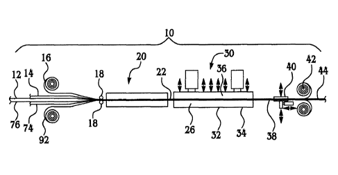
Referring to Figure 1, a CCM fabrication line 10 broadly
may include a pre-forming zone 20, and a consolidation station
30. Multiple plies 12, 14 of composite materials are supplied
either from continuous rolls (not shown) or in the form of
tacked stacks (not shown) of precut blanks. The plies 12, 14 of
composite material are fed along with sheet members forming
mandrels 16, 92 to the pre-forming zone 20. Guides 18 or other
tooling elements may be used to pre-align and guide the plies
12, 14 along with mandrels 16, as well as optional filler
materials (not shown) into the pre-forming zone 20.
The
preformed material plies 12, 14 and mandrels 16 may be passed
through an oven (not shown) to elevate the temperature of the
ply materials in order to facilitate the pre-forming operations
at preforming zone 20. Various features such as part flanges
(not shown), for example, may be preformed in the pre-forming
zone 20 using pressure applied to the plies 12, 14 using rollers
18 or other forming tools.
The preformed part 22, which has the general shape of
the final part, exits the pre-forming zone 20 and moves into the
consolidating operation 30.
The consolidating operation 30
includes a plurality of standardized tool dies generally
indicated at 36, that are individually mated with tool members
(not shown) which have smooth outer surfaces engaged by the
standardized dies, and inner surfaces that have tooled features.
These tooled features are imparted to the preformed part 22
during the consolidation process.
The commonality of the
surfaces between the standardized dies 36 and the outer surfaces
of the tool members eliminates the need for part-specific
matched dies.
The consolidating operation 30 includes a pulsating
drive mechanism 40 that moves the preformed part 22 forward
7
CA 02673448 2014-03-03
06-0960 PCT
within the consolidating operation 30 and away from the pre-
forming zone 20, in continuous, incremental steps.
As the
preformed part 22 moves forward, the preformed part 22 first
enters a heating zone 26 that heats the preformed part 22 to a
temperature which allows the free flow of the polymeric
component of the matrix resin in the plies 12, 14.
Next, the preformed part 22 moves forward into a
pressing zone or operation 32 wherein standardized dies 36 are
brought down collectively or individually at predefined
pressures sufficient to compress and consolidate (i.e. allow
free-flow of the matrix resin) the various plies 12, 14 into the
desired shape and thickness.
As the dies 36 are opened, the
preformed part 22 is incrementally advanced within the
consolidation operation 30, following which the dies 36 are
closed again, causing successive sections of the part 22 to be
compressed within different temperature zones, and thereby
consolidate the laminate plies in the compressed section. This
process is repeated for each temperature zone of the die 36 as
the part 22 is incrementally advanced through the consolidation
operation 30.
The fully formed and compressed (consolidated) part 22
then enters a cooling zone 34 which is separated from the
pressing zone 32, wherein the temperature is brought below the
free-flowing temperature of the matrix resin in the plies 12,
14, thereby causing the fused or consolidated part 22 to harden
to its ultimate pressed shape. The consolidated and cooled part
38 then exits the consolidating operation 30, where the mandrels
16 are taken up on rollers 42. The final formed TPC part 44 is
removed at the end of the line 10.
Although a CCM process has been described above for
purposes of illustration, it should be noted that other molding
processes may be used, including, but not limited to pultrusion
or roll forming.
8
CA 02673448 2014-03-03
06-0960 PCT
Figure 2 is a simplified view of the CCM line 10 shown
in Figure 1 in which a plurality of tacked plies 74 are advanced
incrementally through the pre-forming zone 20 and the
consolidating operation 30. Movement of the tacked plies 74 is
caused by the pulsating drive mechanism 40 which effectively
grabs the end 83, shown in Figure 3, of the finished, fully
formed part 76 as it exits the consolidating operation 30.
At the end of a production run, some amount of the ply
materials 74 are excess because portions of the ply materials 74
remain within the CCM line 10 when production is terminated.
This excess material is illustrated in Figure 3, wherein the
finished part 76 has a finished length 78 with connected links
of excess material designated as scrap 80, 82 respectively on
the trailing and leading ends of the finished length 78. The
primary reason for the scrap 82 on the leading end of the part
76 is due to the fact that the pulsating drive mechanism 40
extends beyond the consolidating zone 30, and a length of the
fully formed part 76 must be advanced beyond the consolidating
zone 30 before the pulsating drive mechanism 40 can grasp the
end of the part 76. The distance between the pulsating drive
mechanism 40 and the end of the consolidating operation 30
therefore corresponds to the length of the scrap 82 at the
leading end of the part 76.
The primary cause for the scrap 80 on the trailing end
of the part 76 is a result of the need to maintain a constant
gap throughout the length of the presses in the consolidating
operations 30. More particularly, is necessary to have the
press elements (not shown) in the consolidating operation 30
applying constant pressure on the part 76 until the part 76 has
completely exited the consolidating operations 30. Otherwise,
unequal pressure may be applied by press platens to the end of
the part 76 during the consolidation process which could deform
9
CA 02673448 2014-03-03
06-0960 PCT
portions of the part 76 or result in uneven pressures being
applied during the consolidation process.
As previously discussed, the length of the scrap 80, 82
at the end of a production run may not be significant where the
materials being used are inexpensive or where the production
runs are high volume, however in the case of the use of
expensive materials or short production runs, the cost of the
scrap 80, 82 may be significant.
In accordance with the
. disclosed embodiments, this scrap may be eliminated using
tooling 84 shown in Figures 4-7.
In the illustrated example, the finished part 76 is U-
shaped in cross section (Figure 3) and has a uniform wall
thickness throughout its length. The tooling 84 includes a tool
body 86 having a central section 92, and leading and trailing
ends 98, 100 respectively on opposite ends of the central
section 92.
The tool body 86 has a U-shaped cross section
defined by a top wall 86a and side walls 86b, 86c which possess
a thickness "t". The central section 92 of tool body 86 has a
reduced wall thickness defining a recess 88 in the outer surface
of all three walls 86a, 86b, 86c. As best seen in Figure 7, the
depth of the recess 88 is substantially equal to the wall
thickness of the part 76 so that the outer surface of the part
76 and the tool body 86 are substantially coplanar after the
part 76 has been fully consolidated. The length of the recess
88 corresponds to the length of the finished part 76.
The recess 88 defines a pair of oppositely facing
shoulders 96 within the thickness of the walls 86a, 86b and 86c
against which the ends of the part 76 may abut so as to prevent
longitudinal movement of the part 76 relative to the tool body
84.
Although the tooling 84 has been described in connection
with its use to form a relatively simple, U-section part of
constant wall thickness, other configurations of the tool body
CA 02673448 2014-03-03
06-0960 PCT
86 can be employed to fabricate other part shapes. For example,
the recess 88 may possess surface features or a non-uniform
depth in order to produce a part 76 having the same surface
features or a non-uniform wall thickness. Furthermore, the tool
body 86 may be curved along its length in order to produce parts
76 that are also curved along their length.
Figure 8 illustrates a tool body 86 with a recess 88a
having a sloping bottom 102 that extends along at least a
portion of the length of body 86. It should be noted however,
that the depth of the recess 88a may also vary across the width
and/or the length of the body 86. The recess 88a may have areas
that are of either uniform and non-uniform depth, or both. The
sloping bottom 102 creates a depth variation in the recess 88a
which, during the consolidation process, causes the formation of
a part 76a having a tapered wall thickness. The recess 88a may
have tooling features such as the raised area 104 which produce
corresponding shapes in the part 76a.
In the example
illustrated in Figure 8, the raised area 104 forms a pocket 106
in a bottom surface of the part 76a.
In use, as best seen in Figure 6, the tacked laminate
plies 74 are placed within the recess 88 of the tool body 86,
with the ends of the plies 74 engaging the shoulders 96 in the
top wall 86a.
The combination of the tool body 84 and the
laminate plies 74 are fed into the pre-forming zone 20 where the
laminate plies 74 are partially formed over exterior surfaces of
the tool body 84, which in the illustrated embodiment, comprise
the outside surfaces of the walls 86b, 86c. The leading end 98
of the tool body 84 enables the pulsating drive mechanism 40 to
pull the tool body 84 along with the part 76 through the CCM
line 10.
During the initial feed process, the leading end 98 of
tool body 84 passes through the pulsating drive mechanism 40
just before the laminate plies 74 reach the pre-forming zone 20.
11
CA 02673448 2014-03-03
06-0960 PCT
In other words, the length of the leading end 98 of tool body 84
is such that the pulsating drive mechanism 40 is able to grasp
the tool body 84, and begin advancing the tool body 84 before
the laminate plies 74 actually reach the pre-forming zone 20.
Although not specifically shown in Figures 2-7, mandrels (Figure
1) comprising thin steel sheets may be applied to the non-tooled
sides of the part 76.
As the pulsating drive mechanism 40 pulls the tool body
84 forwardly, the laminate plies 74 are pressed over the tool
body 84 so as to pre-form the part, following which the
preformed part, designated as 76a in Figure 6 enters the
consolidation operations 30 where the laminate plies are heated
and compressed using the continuous compression molding
techniques previously described. Pressing elements (not shown)
in the consolidation station 30 bear against the mandrels 16
(Figure 1) which apply pressure to the preformed part 76a until
the part reaches the desired shape and is fully consolidated.
Continued movement of the tool body 84 carries the
finished part 76 completely through the consolidation
operations, with the trailing end 100 of tool body 84 remaining
in the consolidation station 30 until the finished part 76 has
completely emerged from the pulsating drive mechanism 40 and any
other related processing equipment, and until the part 76 can be
removed from the tool body 84. The trailing end 100 of the tool
body 84 functions, in effect as a shim to maintain the alignment
of the presses within the consolidation operations 30 until the
part 76 completes the consolidation cycle. Because the trailing
end 100 of the tool body 84 remains within the consolidation
operations 30 until consolidation of the part 76 is complete,
gaps within the press elements within the consolidation
operations 30 remain constant, even as the trailing end of the
finished part 76 emerges from the consolidation operations 30.
12
CA 02673448 2014-03-03
06-0960 PCT
It can be appreciated that by using tooling 84 having a
tool body 86 that has extended leading and trailing ends 98,
100, the scrap represented at 80, 82 shown in Figure 3 is
eliminated since these two scrap sections 80, 82 previously
served a purpose similar to that of the leading and trailing
ends 98, 100, having a respective length 94.
The tool body 84 may be constructed from any of various
metals such as, but not limited to, stainless steel, and may be
reused. The recess 88 in the tool body 86 may be created by
machining the outer surface of the tool body 84 to a depth equal
to the thickness of the consolidated laminate plies of the part
76.
Although the embodiments of this disclosure have been
described with respect to certain exemplary embodiments, it is
to be understood that the specific embodiments are for purposes
of illustration and not limitation, as other variations will
occur to those of skill in the art.
13