Note: Descriptions are shown in the official language in which they were submitted.
CA 02673476 2015-10-23
PRE-AGGREGATE DRYING METHOD AND ENERGY EFFICIENT
ASPHALT PLANT
FIELD OF THE INVENTION
The present invention generally relates to hot mix asphalt (HMA) plants
used in road paving.
BACKGROUND OF THE INVENTION
In recent years, attempts have been made to improve the efficiency of hot
mix asphalt (HMA) plants. Conventional direct-fired prior art drum hot mix
2
CA 02673476 2015-10-23
asphalt plants often utilize a mixture of virgin aggregate material and
recycled
asphalt products (RAP). This virgin aggregate is generally stockpiled until it
is
needed. It is often exposed to the atmosphere and to rain, snow, etc. The
moisture
content of virgin aggregate can vary, but it is often not insignificant. As a
constituent of HMA, the virgin aggregate is necessarily heated far above the
boiling point of water during the asphalt production process. This heating
across
the vaporization point (which also dries the virgin aggregate) consumes a
large
amount of energy. Much of the total energy supplied to a drum heater in an
asphalt
plant is consumed in heating and drying the constituents of IIMA, including
virgin
aggregate material.
Consequently, there exists a need for improved methods and systems for
cost effectively heating and drying virgin aggregate material used in asphalt
production.
SUMMARY OF THE INVENTION
Accordingly, the present invention seeks to provide a system and method for
producing asphalt in an efficient manner.
It is a feature of the present invention to utilize a virgin aggregate feed
bin
with an integrated dryer.
3
CA 02673476 2009-07-21
It is another feature of the present invention to use atmospheric or heated
air to pre-dry/heat virgin aggregate material.
It is another feature of the present invention to include capturing exhaust
and other wasted heat from various portions of an asphalt plant and using it
to dry
and pre-heat virgin material.
It is another feature of the present invention to use a heat exchanger to
convert humid exhaust air to heat air to dry virgin aggregate material.
It is yet another feature of the present invention to reduce the emission of
gaseous and liquid sulfuric and other acids by maintaining separation between
exhaust gases used to heat the HMA to a point above the boiling point of water
and moisture given off by the HMA mixture when it is heated above the boiling
point of water, while both are used separately to heat the air used to heat
the virgin
aggregate.
It is an advantage of the present invention to provide a relatively high
efficiency HMA plant.
The present invention is designed to satisfy the aforementioned needs,
provide the previously stated objects, include the above-listed features, and
achieve the already articulated advantages.
4
CA 02673476 2015-10-23
In a broad aspect, the invention pertains to an asphalt plant comprising an
asphalt
mixer, a supply of aggregate material, a structure constructed for enclosing
and containing aggregate
material and protecting the aggregate material from precipitation and further
comprising components
configured to allow air to flow through the aggregate material for the purpose
of drying the aggregate
material with at least one of atmospheric air and artificially heated and
propelled atmospheric air.
There is provided a conveyor to move the aggregate material from the structure
into the asphalt
mixer. The structure is configured to permit air to pass through a
substantially stationary
arrangement of The aggregate irrespective of the operation state of the
asphalt mixer. The artificially
heated and propelled air is incidentally heated, via heat generated for
purposes other than just pre-
heating aggregate, during operation of the asphalt mixer and captured from
surfaces of the asphalt
mixer, and further comprises a heat exchanger which captures heat from moist
exhaust fumes of the
asphalt mixer, and further heats air which is more dry and is moved into the
structure and through the
substantially stationary aggregate arrangement of aggregate material.
In a further aspect, the invention provides a method of making hot mix asphalt
comprising the
steps of providing an asphalt mixer, providing a supply of aggregate material,
and providing an
aggregate material storage structure which is configured for enclosing and
containing a first quantity
of aggregate material and protecting the first quantity of aggregate material
from atmospheric
precipitation, and further causing air to flow through the first quantity of
aggregate material for the
purpose of drying the first quantity of aggregate material with mechanically
propelled air, and causing
the first quantity of aggregate material to move from the structure into the
asphalt mixer.
Still further, the invention provides a method of making asphalt comprising
the steps
providing a first airstream of moist heated air at a first location, using a
fan to move the airstream to
a heat exchanger. The heat exchanger gives up reclaimed heat energy as the
moist heated air cools
and condenses in the heat exchanger, transferring the reclaimed heat energy to
a second location, via
a second airstream, which is not in fluid communication with the first
airstream. At the second
location, and before both entering a mixer and outside of any mixer, the
second airstream is caused to
flow into a structure and through aggregate material to produce heated
aggregate material, using the
heated aggregate material to make asphalt.
CA 02673476 2015-10-23
BRIEF DESCRIPTION OF THE DRAWINGS
The invention may be more fully understood by reading the following
description of the preferred embodiments of the invention, in conjunction with
the
appended drawings wherein:
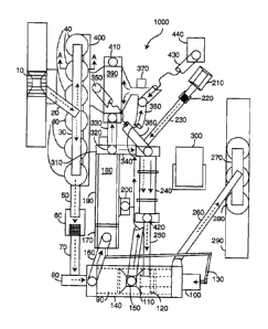
Fig. 1 is a plan view of an HMA plant of the present invention where the
long dashed line arrow represents direction of flow of various bulk materials
through the plant.. The dotted lines represent flow of gaseous matter with
suspended small particulate matter. The solid arrowed lines represent a
connection
between portions of a pipe, etc. which is not drawn to reduce potentially
confusing
6
CA 02673476 2009-07-21
clutter in the drawings. The double-arrowed line A-A is a line along which the
cross-sectional view of Fig. 2 was taken. The intermittent lines without
arrowheads show otherwise hidden internal components.
Fig. 2 is a cross-sectional view of the virgin aggregate feeder bin with
integrated heater/dryer unit of the present invention taken on line A-A of
Fig. 1.
The solid arrows represent airflow.
Fig. 3 is a cross-sectional view of an alternate embodiment of a virgin
aggregate feed bin with integrated heater/dryer unit of the present invention
taken
on line A-A of Fig. 1. The solid arrows represent airflow.
DETAILED DESCRIPTION OF THE INVENTION
Now referring to the drawings, wherein like numerals refer to like matter
throughout, and more specifically to Fig. 1, there is shown energy efficient
HMA
plant 1000 which can be generally constructed of the same types of materials
and
in the same general manner as prior art HMA plants. Energy efficient HMA plant
1000 is shown as including a drive-over truck dump 10, or the like, which can
be
used for receiving virgin aggregates from trucks or end loaders, etc. Note:
throughout this description, virgin aggregate products are mentioned as HMA
7
CA 02673476 2009-07-21
components which benefit from preheating. It should be understood that virgin
aggregate is used as an example, and the present invention is intended to
cover
recycled or reclaimed aggregate material and any other non-RAP dry bulk
component of LIMA. Although this invention is described as related to IIMA, it
should be understood that it could be used with warm mix asphalt, etc. Drive-
over
truck dump 10 feeds the virgin aggregate material onto bin supplying conveyor
20
which may be an inclined conveyor carrying virgin aggregate material to the
top
of virgin aggregate feed bins 40. Reversing translating conveyor 30 can move
virgin aggregate material either left or right to feed the various virgin
aggregate
feed bins 40. Aggregate feed bins 40 can be from a small size to very large,
on the
order of approximately 10 tons to a thousand ton or more capacity.
Virgin aggregate feed bins 40 can be circular, rectangular or other shapes.
Virgin aggregate feed bins 40 are designed so that heated air can enter from
the
bottom and pass through the virgin aggregate material therein and heat and dry
the
virgin aggregate material. Depending on the moisture content of the virgin
aggregate material and the humidity, either ambient air or heated air is moved
through the virgin aggregate material. Virgin aggregate feed bins 40, as well
as
every other portion of the present invention that contains or carries heated
matter,
could be thermally insulated.
8
CA 02673476 2009-07-21
Gathering conveyor 50 is disposed below virgin aggregate feed bin 40
(more clearly shown in Figs. 2 and 3). Also, sec discussion of Figs. 2 and 3
below.
The heated and dried virgin aggregate material is delivered by gathering
conveyor
50 to vibrating screen 60 which may be a single or multi-deck screen which
removes oversize or foreign objects from the supply of virgin aggregate
material.
Grizzly bars, tronunels and other material sorting devices could be used with
or
instead of vibrating screen 60.
Once the virgin aggregate material is processed, it is supplied on weigh
conveyor 70 which weighs the virgin aggregate material as it is delivered to
slinger 80, other high speed conveyor or feed slide chute which propels or
provides the virgin aggregate material into the virgin aggregate material
intake end
of drum dryer/mixer 90. (While no electronic data or control lines are shown
connecting the various components of the present invention, it should be
understood that various wired or wireless connections may be preferred in some
applications.) A counter-flow mixer is shown, but a parallel flow mixer or
suitable
substitute could be used as well. Discharge and burner housing 100 is shown
disposed over the HMA discharge end of drum dryer/mixer 90. Burner head 110 is
shown, with phantom lines, centrally disposed inside drum dryer/mixer 90 as is
commonly done with prior art counter-flow mixers. RAP entry collar 120 is
shown
in a similar manner. Dust return auger system 130 is shown in a typical
manner.
9
CA 02673476 2009-07-21
Drum heat collecting hood 140 is disposed over the heating and drying portion
of
drum dryer/mixer 90 as well as the mixing portion. A single or multiple heat
collecting hoods could be used. Drum heat collecting hood outlet duct 150 is
shown as the sole, non-exhaust, heated air removing duct from drum dryer/mixer
90. The drum heat collecting hood outlet duct 150 and the hood itself are
incidentally heated. The term "incidentally heated" should be understood to
mean
that the hood receives heat as the result of a process other than
intentionally
heating the hood for pre-drying and pre-heating aggregate material before it
is
introduced into a mixer. Here the drum heat collecting hood outlet duct 150
and
hood are indirectly and incidentally heated as a result of the burner head 110
within the drum dryer/mixer 90 in its normal operation of creating HMA. Due to
low pressure, the heated air is sucked from drum heat collecting hood outlet
duct
150 to valve ducting 380.
Drum dryer/mixer exhaust gas hood and ducting 160 removes the heated
exhaust fumes of drum dryer/mixer 90 and provides it to course collector 170,
which removes the courser portion of the airborne or air-blown fines and dust
suspended or otherwise combined within the gaseous exhaust.
Course collector 170 is coupled directly to filterhouse 180 and coupled
back to drum dryer/mixer 90 via dust return auger system 130. Filterhouse 180,
also known as a baghouse, filters dust and finer matter from the exhaust
airstream
CA 02673476 2016-06-08
exiting course collector 170. Course collector and filterhouse heat collecting
hood 190 is
disposed over both curse collector 170 and filterhouse 180, and it collects
heat which
otherwise would be lost to the atmosphere. Collector or collector hood 200
gathers the
heated air from course collector and filterhouse heat collecting hood 190 and
combines it
with the heated air from drum heat collecting hood outlet duct 150 via a tee
(shown
symbolically as a mere line abutting another line) in drum heat collecting
hood to valve
ducting 380. Duct dampers allow the heated air from course collector and
filterhouse
heat collecting hood 190 and drum heat collecting hood outlet duct 150 to be
balanced.
The recycled asphalt products (RAP) enter the system via RAP feed bin 210
which is coupled to vibrating screen 220 and RAP weigh conveyor 230 which
weighs the
RAP to be provided into RAP pre-heater/dryer 240 which could be similar to a
RAP pre-
heater as described in co-pending U.S. patent application having serial number
12/138,204 filed by the same inventor and assigned to the same assignee, which
application was published on 12/18/2008 with number US 2008-0310249-Al, which
may
be referred to for further details, RAP pre-heater/dryer 240 heats and dries
the RAP and
provides the same on pre-heated RAP supplying conveyor into RAP entry collar
120,
RAP dryer exhaust slack 420 is also shown.
11
CA 02673476 2009-07-21
Drum dryer/mixer 90 outputs HMA on HMA outputting conveyor 260
which carries the HMA to reversing HMA transfer conveyor 270 (similar in
operation to reversing translating conveyor 30, but with appropriate changes
owing to the temperature and consistency of I IMA) to LIMA storage silos 280,
which may be disposed over top of a scale 290 for weighing trucks being loaded
with the HMA.
It should be noted that not all aspects of a typical counter-flow HMA mixer
are shown, such as the asphalt cement storage and metered delivery apparatus,
as
well as other heating means, etc. This description assumes the use of typical
prior
art systems and methods unless alternate ways are suggested.
Plant control house 300 is shown disposed centrally and without physical
connection to the various segments of the overall system. Of course, both
wired
and/or wireless systems and components could be utilized. Power for each
component of the present system could be provided via a power plant at each
major unit or one or more power plants or electric generators which distribute
power or electricity to the various system components.
First exhaust fan 310 draws or sucks air through the drum dryer/mixer 90,
course collector 170, filterhouse 180 and pushes or blows air into heat
exchanger
390 and RAP pre-heater/dryer 240. First balancing valve 320 could be used to
12
CA 02673476 2009-07-21
balance airflow between heat exchanger 390 and RAP pre-heater/dryer 240 or
shut
off flow via first fan to RAP dryer duct 340.
Valve 350 can send dry pre-heated air to RAP pre-heater/dryer 240 instead
of or in combination with air from first exhaust fan 310. Valve to RAP dryer
duct
360 carries hot dry air to RAP pre-heater/dryer 240. Second exhaust fan 370
pulls
or sucks air from drum heat collecting hood 140, course collector and
filterhouse
heat collecting hood 190, generator 440 and possibly from other sources of
heat
which are not mentioned or shown and also pushes or blows air into heat
exchanger 390 where the air is further heated by exhaust air coming from first
exhaust fan 310. This heated dry air is then blown into virgin aggregate
drying
distribution duct 400 that distributes air to any and all of the virgin
aggregate feed
bins 40 and to the RAP pre-heater/dryer 240.
Drum heat collecting hood to valve ducting 380 is the duct from the drum
dryer/mixer 90 and its drum heat collecting hood 140 to second exhaust fan
370. A
balancing valve could be used at the inlet of second exhaust fan 370 to
balance
airflows from drum heat collecting hood to valve ducting 380 and generator to
second exhaust fan heat carrying duct 430 as they enter second exhaust fan
370.
Heat exchanger 390 takes heat from the airstream coming from the
filterhouse 180 through first fan to heat exchanger duct 330. This air,
besides
13
CA 02673476 2009-07-21
being hot (which normally may be between 212 degrees F to 400 degrees F) also
contains high level of moisture. This moisture when cooled in the heat
exchanger
condenses and gives up a large amount of heat energy. Heat exchanger 390 will
have a water drain. The sensible heat and the condensation heat given up by
this
airstream is transferred to air from second exhaust fan 370 in heat exchanger
390.
This heated dry air is sent or blown to and through virgin aggregate drying
distribution duct 400 to heat and dry the virgin aggregate material or sent to
the
RAP pre-heater/dryer 240. Additional fans could be deployed to increase the
velocity of air which is blown through virgin aggregate drying distribution
duct
400.
It should be noted that second exhaust fan 370 could be left running when
the rest of the plant is off for hours or days. This will use the heat in the
thermal
mass of the drum dryer/mixer 90, course collector 170, and course collector
and
filterhouse heat collecting hood 190 to continue to dry the virgin aggregate
material in virgin aggregate feed bins 40. Even after such items have cooled,
ambient air alone will continue to remove surface and internal moisture from
virgin aggregate material.
Virgin aggregate drying distribution duct 400 can have on/off and
balancing valves to control where and how much air goes to each virgin
aggregate
feed bin 40.
14
CA 02673476 2009-07-21
Also shown are heat exchanger exhaust stack 410 and RAP dryer exhaust
stack 420.
Generator to second exhaust fan heat carrying duct 430 carries wasted heat
from the generator 440 to the second exhaust fan 370. This heat can be from
any
source of heat associated with the generator 440. In some embodiments, no
generator 440 will be used as power lines are used to provide electricity from
a
utility.
Now referring to Figs. 2 and 3, there is shown a distribution duct to feed
bin metering valve 450 for controlling airflow to each virgin aggregate feed
bin
40. Below the virgin aggregate feed bin 40 is virgin aggregate feeder unit 460
which is used to control the rate of flow of material onto gathering conveyor
50.
Heated airflow path 470 represent typical paths of heated air through the
virgin aggregate material during the heating and drying process. Airflow
permitting internal bin virgin aggregate barrier 480 forms the bottom and/or
portions of the internal virgin aggregate material containing walls of virgin
aggregate feed bin 40. Airflow permitting internal bin virgin aggregate
barrier 480
may be passageways or specially designed baffles, etc. which permit air to
flow
therethrough while containing the virgin aggregate material.
CA 02673476 2015-10-23
Post virgin aggregate airflow path 490 represents a typical airflow path of
air carrying moisture after it has passed through the virgin aggregate
material.
This air passes through weatherproof bin vent 500.
Below virgin aggregate feed bin 40 is access tunnel 510 which could be
concrete or other suitable material. Deployable rain cover 520 is also shown
atop
of virgin aggregate feed bin 40 which can be opened when virgin aggregate
material is being moved into the virgin aggregate feed bin 40 and closed at
other
times to prevent rain, snow, animals, etc. from entering the virgin aggregate
feed
bin 40.
Virgin aggregate feed bin 40 could include therein one or more augers for
the purpose of mixing the virgin aggregate material disposed therein so as to
improve drying and uniformity of the drying of the virgin aggregate material.
It is thought that the method and apparatus of the present invention will be
understood from the foregoing description and that it will be apparent that
various
changes may be made in the form, construct steps, and arrangement of the parts
and steps thereof, without departing from the scope of the invention as
defined in the claims appended herein. The form herein described is merely
a preferred exemplary embodiment thereof.
16