Language selection

Search

Patent 2673693 Summary

Third-party information liability

Some of the information on this Web page has been provided by external sources. The Government of Canada is not responsible for the accuracy, reliability or currency of the information supplied by external sources. Users wishing to rely upon this information should consult directly with the source of the information. Content provided by external sources is not subject to official languages, privacy and accessibility requirements.

Claims and Abstract availability

Any discrepancies in the text and image of the Claims and Abstract are due to differing posting times. Text of the Claims and Abstract are posted:

  • At the time the application is open to public inspection;
  • At the time of issue of the patent (grant).
(12) Patent Application: (11) CA 2673693
(54) English Title: TANK SPRAYER WITH SEPARATE CONCENTRATE CONTAINER
(54) French Title: PULVERISATEUR AVEC CONTENANT DE CONCENTRE SEPARE
Status: Dead
Bibliographic Data
(51) International Patent Classification (IPC):
  • B05B 7/32 (2006.01)
  • B05B 9/04 (2006.01)
  • B05B 11/06 (2006.01)
  • B05B 11/00 (2006.01)
(72) Inventors :
  • CLARKE, MICHAEL T. (United States of America)
(73) Owners :
  • ROOT-LOWELL MANUFACTURING COMPANY (United States of America)
(71) Applicants :
  • ROOT-LOWELL MANUFACTURING COMPANY (United States of America)
(74) Agent:
(74) Associate agent:
(45) Issued:
(22) Filed Date: 2009-07-23
(41) Open to Public Inspection: 2010-01-23
Examination requested: 2014-07-22
Availability of licence: N/A
(25) Language of filing: English

Patent Cooperation Treaty (PCT): No

(30) Application Priority Data:
Application No. Country/Territory Date
12/178,093 United States of America 2008-07-23

Abstracts

English Abstract


A manually pressurizable house and garden tank sprayer employing a separate
diluent tank and liquid chemical concentrate container, wherein the
concentrate container is
mounted to and carried by the diluent container or by a spray wand. The tank
containing diluent
is pressurized by a conventional hand pump, and the same hand pump pressure
pressurizes the
concentrate container. The diluent and concentrate chemical are not admixed
until just before
the liquids are dispensed, so that unused chemicals are not contaminated or
diluted until they are
used.


Claims

Note: Claims are shown in the official language in which they were submitted.


CLAIMS
1. A tank sprayer with separate concentrate container carried by the sprayer,
comprising:

a pressurizable diluent container having an open interior and an inlet with a
removable cover, the diluent container including a pump for pressurizing the
interior of the
container with gas pressure, the diluent container having a liquid outlet for
discharging diluent,
the liquid outlet being in fluid communication with the interior of the tank
at a position adjacent
a lower portion of the tank, such that gas pressure in the tank forces liquid
in the tank out of the
liquid outlet;

a separate pressurizable liquid concentrate container for holding liquid
chemical
concentrate that is to be admixed with the diluent before being applied to
lawn or garden
vegetation or other target material, the concentrate container having an open
interior and an open
top that is closed by a removable cap, the interior of the concentrate
container being
pressurizable when the top is closed, the concentrate container having a gas
inlet for pressurized
gas and a liquid outlet for pressurized liquid concentrate, the liquid outlet
being in
communication with the interior of the concentrate container at a position
adjacent a bottom
thereof such that gas pressure applied to the interior of the concentrate
container through the gas
inlet urges liquid concentrate to flow out of the concentrate container
through the liquid outlet
when the top is closed;

a liquid dispenser comprising a spray wand for spraying liquid from the
diluent container
and concentrate container, the wand being actuated by a manually actuable
shutoff valve, the

8


wand having an inlet that is connected to the diluent container liquid outlet
by a flexible delivery
tube;

attachment means for releasibly mounting the liquid concentrate container on
one of the
diluent container and the liquid dispenser, such that the liquid concentrate
container is carried by
the diluent container or the liquid dispenser;

a gas pressure tube interconnecting the diluent container with the concentrate
container,
the pressure tube having an inlet in communication with pressurized gas in the
interior of the
diluent container and having an outlet in communication with the interior of
the liquid
concentrate container, such that gas pressure in the diluent container is
transmitted through said
tube to the concentrate container so as to pressurize the interior of the
concentrate container
when the top of the concentrate container is closed and the diluent container
is pressurized;

a diluent conduit for conveying pressurized liquid diluent from the diluent
container
liquid outlet to a liquid inlet on the spray wand;

a concentrate conduit for conveying pressurized liquid concentrate from the
liquid
concentrate container outlet to the spray wand separately from the diluent,
the concentrate
conduit having an outlet in fluid communication with the liquid diluent such
that the spray wand

nozzle discharges a combination of liquid concentrate and liquid diluent at
the spray nozzle, and
such that the liquid diluent and liquid concentrate are admixed before
discharge from the spray
nozzle but are not admixed in the diluent container or concentrate container,
preventing

contamination of the liquid in the concentrate container with liquid from the
diluent container,
the concentrate and diluent being dispensed by pressure received from the
diluent tank pump, the
single pump reducing cost and facilitating dispensation while ensuring that
there is a continuous
relationship between the pump pressure that causes liquid dispensation from
both containers.

9


2. A tank sprayer as in claim 1 wherein the diluent container includes a
recess in the
side thereof that resiliently engages and holds the concentrate container
therein, such that the
concentrate container can be carried by the diluent container.

3. A tank sprayer as in claim 2 wherein the recess is shaped to fit partially
around
the concentrate container, with the diluent container having spaced apart
outer side edges that
render the side of the concentrate container visible when the concentrate
container is mounted in
the diluent container.

4. A tank sprayer as in claim 1 wherein the concentrate container is
releasibly
mounted on the liquid dispenser.

5. A tank sprayer as in claim 4 wherein the concentrate container is mounted
on the
liquid dispenser by means of a releasible fastener on a cap connected to a
handle of the liquid
dispenser, the cup releasibly engaging and closing the open top of the
concentrate container such
that the concentrate container is pressurized when the diluent tank is
pressurized.

6. A lawn and garden tank sprayer with separate concentrate container
comprising:
a diluent tank comprising a pressurizable container having an open interior
and a
closeable top, the tank including a manually operable air pump to pressurize
the interior of the
tank, the tank including a liquid outlet for discharging liquid diluent from
the tank in response to
pressure in the tank, the liquid outlet being in communication with a lower
portion of the interior


of the tank, the tank further including a gas outlet for conveying pressurized
air from the tank,
the gas outlet being in communication with an upper portion of the interior of
the tank;

a separate, pressurizable concentrate container for dispensing concentrate
liquid, the
concentrate container having an open interior and a closeable top, the top
having a gas inlet for
conveying pressurized gas to the interior of the concentrate container, the
top further having a
liquid outlet in communication with a lower portion of the interior of the
concentrate container
for conveying liquid concentrate from the concentrate container in response to
pressure in the
container;

a manually operable liquid dispenser comprising a spray wand having a handle
with a
manually operable actuator and having an outlet nozzle at an outer end, the
handle having
separate inlets for diluent liquid and concentrate liquid, the inlets merging
in a junction in the
dispenser so as to blend the liquids before the liquids are discharged from
the nozzle, such that
the liquids remain separate and reusable until just before they are discharged
from the nozzle;

a gas pressure tube connected between the diluent tank gas outlet and the
concentrate
container gas inlet so as to pressurize the concentrate container with
pressurized gas from the
diluent container;

a liquid tube connected between the diluent tank liquid outlet and the diluent
liquid inlet
of the liquid dispenser;

a liquid tube connected between the concentrate container liquid outlet and
the
concentrate liquid inlet of the liquid dispenser; and

a concentrate container mounting mechanism incorporated into one of the
diluent tank
and dispenser, the concentrate container being mounted on the diluent tank or
dispenser by the
11


mounting mechanism, such that the concentrate container is automatically
transported with the
diluent container or dispenser.

7. A lawn and garden tank sprayer as in claim 6 wherein the concentrate
container
comprises a bottle having a diameter substantially smaller than a diameter of
the diluent
container, the mounting mechanism comprising an integral recess in the diluent
container in
which the concentrate container bottle fits, so as to be carried with the
diluent container.

8. A lawn and garden tank sprayer as in claim 7 wherein the recess comprises
an
indentation formed in the side of the diluent container, the indentation
having opposed outer
edges that are spaced apart by less than a diameter of the concentrate bottle,
the concentrate
bottle fitting into the indentation, a side of the bottle being translucent
and being visible through
the spaced outer edges of the indentation, such that the amount of liquid
concentrate remaining in
the concentrate container is visible through the side of the bottle when the
bottle is mounted in
the indentation.

9. A lawn and garden sprayer as in claim 1 wherein a cap for closing the open
top of
the concentrate container is mounted in the spray wand, the cap having a
releasable and sealable
fastener thereon that fits on and holds the open top of the concentrate
container, such that, when
attached to the dispenser, the concentrate container is carried by the
dispenser.

12

Description

Note: Descriptions are shown in the official language in which they were submitted.


CA 02673693 2009-07-23

TANK SPRAYER WITH SEPARATE CONCENTRATE CONTAINER
BACKGROUND OF THE INVENTION

[0001] The present invention relates to a tank sprayer having a separate
concentrate
container that is carried by the tank or by the chemical dispenser.

[0002] A typical tank sprayer for home and garden use is a liquid chemical
dispenser
device for dispensing a mixture of a liquid chemical and diluent. A tank
sprayer typically
includes a liquid container or tank pressurized by a hand pump integrated into
a removable top or
closure for the container. Liquid in the tank is dispensed by the pressure in
the tank through a
hose or tube that leads to a nozzle on a spray wand, which is operated by a
trigger valve. To use
a tank sprayer, liquid from a concentrate container is usually poured into the
tank and mixed with
water (or other diluent) in the tank. The tank is then closed and pressurized
with the pump
incorporated in the tank top, and liquid is sprayed with the spray wand. When
the spraying is
done, the remaining portion of liquid in the tank is often either discarded or
stored in the tank or
some other container, creating a question regarding the strength and identity
of the mixture at a
later date because the tank is not labeled with the manufacturer's product. In
systems where a
concentrate can be housed in a separate container so it is not mixed with a
diluent, it can be
cumbersome to transport the diluent tank along with a separate concentrate
container.

[0003] An object of the present invention is to provide an improved tank
sprayer
having a pressurizable tank for housing water or other diluent and a separate
pressurizable liquid
container for housing the liquid chemical, with the sprayer discharging both
liquids by positive
pressure from the tank and preventing admixture of the liquids until just
before they are
discharged. A further object of the invention is to provide an attachment
mechanism whereby
1

4144696 vl


CA 02673693 2009-07-23

the separate concentrate container can be conveniently clipped into a recess
in the side of the
diluent tank or screwed into a connector incorporated into the dispensing
wand, and the spray
wand can be clipped into the tank for carrying, making the invention less
cumbersome and more
convenient to transport and use.

SUMMARY OF THE INVENTION

[0004] The present invention comprises a tank sprayer comprising a diluent
container,
concentrate container, hand pump assembly, dispensing assembly, and hose
connections.

[0005] The hand pump assembly enables the user to pressurize the diluent tank
with
pressurized air, thereby forcing the diluent under positive pressure from the
tank. The diluent
travels through a hose or tube into the dispensing wand, where it is mixed
with concentrate from
a separate container before being expelled from a spray nozzle. The
pressurized air in the tank
also pressurizes the concentrate container by means of a hose or tube that
provides pressure
communication between the two containers. The air pressure provided from the
tank forces the
concentrate out of its container and into the dispensing wand, where it mixes
with the diluent
before being expelled from the spray nozzle. In one embodiment, the
concentrate container is
held in place by being resiliently clipped into a recess in the side of the
container. In another
embodiment, the concentrate container is mounted to the wand. In both cases,
the concentrate is
not mixed with diluent until the diluent leaves the tank.

[0006] Because the concentrate is housed separately from the diluent even
during use,
the user does not have to fumble with mixing the liquids, where spills are
common. In addition,
when spraying is complete, the concentrate container may simply be removed
from the tank and
the original cap for the concentrate bottle can be reattached for storage; the
diluent tank can

2
4144696 v1


CA 02673693 2009-07-23

simply be emptied. In addition, because the concentrate container can either
be conveniently
housed in a recess in the wall of the diluent tank or attached to the
dispensing assembly, the
entire system can more easily be handled and transported by the user.

[0007] These and other features, objectives, and benefits of the invention
will be
recognized by one having ordinary skill in the art and by those who practice
the invention, from
this disclosure, including the specification, the claims, and the drawing
figures.

BRIEF DESCRIPTION OF THE DRAWINGS
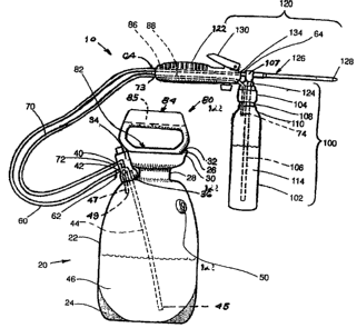
[0008] FIG. 1 is a side elevational view of a first embodiment of the present
invention
showing a liquid chemical dispenser bottle connected to the handle of the
sprayer outlet wand.
[0009] FIG. 2 is a side elevational view of a second embodiment of the present
invention showing a liquid chemical container clipped in a recess in the side
of the sprayer tank.

DETAILED DESCRIPTION OF PREFERRED EMBODIMENT

[0010] In accordance with the present invention, a first embodiment of a tank
sprayer
(hereinafter "sprayer") having a separate liquid chemical container or
concentrate container is
shown in FIG. 1. Sprayer 10 comprises a diluent container or tank assembly 20,
liquid delivery
hose or tube 60, pressure hose or tube 70, hand pump assembly 80, concentrate
or liquid

chemical container assembly 100, and liquid dispensing assembly 120.

[0011] In the embodiment illustrated in FIG. 1, the tank or diluent container
assembly
comprises a hollow, one-piece, molded tank 22 having an elliptical sidewall
configuration and a
plurality of spaced protrusions 24 on the bottom of the tank that serve as
supporting surfaces or
feet for the tank. A mouth or inlet 26 is formed at the top of the tank and
includes a neck 28 and
3

4144696 vl


CA 02673693 2009-07-23

lip 30 surrounding an inlet passage 32 into the open interior of the hollow
tank. A tank outlet
fitting 34 is sealingly mounted on an outlet opening 36 in the outer wall of
the tank at an upper
position on the tank. The tank outlet fitting includes a pressure outlet
fitting 40 and a liquid
outlet fitting 42. An internal diluent outlet tube 44 extends downward from
the liquid outlet
fitting 42 inside the tank to end 45 adjacent the bottom of the tank,
permitting the delivery of
diluent 46 from the tank when the tank is pressurized.

[0012] An external liquid delivery tube 60 for diluent is connected at one end
62 to
liquid outlet fitting 42 outside the tank and terminates at the dispensing
assembly 120 at an
opposite end 64. The dispensing assembly comprises a spray wand 126 having a
handle 122 at
one end and a spray nozzle 128 at the other end. Diluent from the tank travels
through the liquid
delivery tube 60, through end 64, and into the dispensing wand 126 through
tube 86 in handle
122. The diluent is thereafter dispensed through nozzle 128 at the end of the
wand. Trigger
assembly 130 in the handle controls liquid flow through the wand.

[0013] A pressure tube 70 is connected at one end 72 to pressure outlet
fitting 40 at
the outer side of the tank and is connected at the other end 73 to tube 88
extending through
handle 122. Tube 88 extends through cap 104 and terminates at end 74 within a
concentrate
container 102. A pressure tube 47 extends into the tank from fitting 42 to an
end 49 at an upper
portion of the tank for conveying pressurized gas from the tank to pressure
tube 70.

[0014] Hand pump assembly 80 provides a sealed cover for tank inlet 26 and
comprises a conventional hand pump 82 that extends into the tank from a pump
handle 84. The
handle includes a recess or groove 85 in the upper side in which the handle
122 of the spray
wand can be clipped for releasibly fastening the wand to the tank for carrying
the wand along
with the tank. Vertical reciprocation of the pump handle after removal of the
wand therefrom

4
4144696v1


CA 02673693 2009-07-23

pressurizes the tank. This forces the diluent under positive pressure from the
diluent outlet tube,
through the liquid delivery tube 60, ultimately to be expelled from spray
nozzle 128.

[0015] The air pressure that is created in the tank by the hand pump is also
transferred
to the concentrate container 102 via the pressure tube 70, where it
pressurizes the concentrate
container.

[0016] The concentrate container assembly 100 comprises concentrate container
102,
a sealable concentrate container cap 104, and a concentrate outlet tube 106.
An externally
threaded mouth 108 on an open top I 10 of the concentrate container allows the
concentrate
container to be releasably connected to the internally threaded concentrate
container cap 104.
Pressurized air generated in the tank 22 by the hand pump is transferred via
pressure tube 70,
through the dispenser handle, and into the concentrate container, urging
concentrate 114 to travel
under positive pressure through the concentrate outlet tube 106 to junction
107 where the
concentrate and diluent are mixed, just before the concentrate and diluent are
dispensed from the
wand.

[0017] Dispensing assembly 120 includes a concentrate bottle connector 124 at
the
end of handle 122. Concentrate container cap 104 is incorporated in connector
124. With this
embodiment, the concentrate bottle is carried by the spray wand handle as a
component of the
dispensing assembly, with the liquid concentrate chemical and the diluent
(water generally)
being admixed just before they are dispensed, so there is no problem with the
disposal of mixed
chemicals that are not used.

[0018] In a second embodiment 180 of the present invention, shown in FIG. 2,
concentrate container 200 fits snugly within an arcuate seat or recess 204 in
the outer wall of
diluent tank 206. Desirably, recess 204 is shaped to extend around more than
half of the

4144696 vl


CA 02673693 2009-07-23

circumference of the concentrate bottle, with spaced outer edges 205 being
separated apart by a
distance less than the diameter of the bottle, so the bottle will lodge in the
recess and be
restricted from falling out through the open side in the recess. The open
side, however, will
enable the user to see how much concentrate remains in the bottle if a
translucent or transparent
bottle or bottle panel is employed.

[0019] In this embodiment, the tank is also pressurized by a hand pump 208,
forcing
diluent from the tank under positive pressure through a liquid diluent outlet
tube 210 that extends
from an inlet 211 adjacent the bottom of the tank, through tank outlet fitting
217 to delivery tube
212 outside the tank. The liquid diluent then flows to spray wand 216, where
it mixes with
concentrate at a junction in the handle 218 of the spray wand. The liquids are
mixed inside the
wand handle before being expelled from the spray nozzle 230 by trigger valve
214.

[0020] The pressure created by the hand pump is transferred from the pressure
tank
though internal pressure tube 220, through outlet fitting 217, and then
through pressure tube 224,
through the concentrate container cap 222, and into the concentrate container
200. There, the
pressure forces the concentrate into the concentrate outlet tube 226, through
cap 222, and then
into the concentrate delivery tube 228, which extends into the dispensing
wand. The concentrate
then mixes with the diluent at a junction in the wand before being expelled
with the diluent from
the spray nozzle 230. In particular, while the junction of the concentrate and
diluent delivery
tubes desirably is as close to the spray nozzle as possible, in order to
minimize admixture of
liquids that may not be dispensed, the junction can be positioned elsewhere,
as long as the liquids
are mixed after they leave their storage containers. A conventional pressure
relief valve 50 in the
tank walls of both embodiments prevents excessive pressure from building
within the pressure

6
4144696 vl


CA 02673693 2009-07-23

tank and concentrate container. The spray wand clips resiliently within either
of two recesses
232 in the side of the handle for carrying the spray wand with the tank.

[0021] The foregoing is merely exemplary of the preferred practice of the
present
invention, and various changes and modifications may be made in the
arrangements and details
of construction of the embodiments disclosed herein without departing from the
spirit and scope
of the present invention.

7
4144696 0

Representative Drawing
A single figure which represents the drawing illustrating the invention.
Administrative Status

For a clearer understanding of the status of the application/patent presented on this page, the site Disclaimer , as well as the definitions for Patent , Administrative Status , Maintenance Fee  and Payment History  should be consulted.

Administrative Status

Title Date
Forecasted Issue Date Unavailable
(22) Filed 2009-07-23
(41) Open to Public Inspection 2010-01-23
Examination Requested 2014-07-22
Dead Application 2017-02-01

Abandonment History

Abandonment Date Reason Reinstatement Date
2016-02-01 R30(2) - Failure to Respond
2016-07-25 FAILURE TO PAY APPLICATION MAINTENANCE FEE
2016-08-25 FAILURE TO RESPOND TO OFFICE LETTER

Payment History

Fee Type Anniversary Year Due Date Amount Paid Paid Date
Application Fee $400.00 2009-07-23
Maintenance Fee - Application - New Act 2 2011-07-25 $100.00 2011-04-13
Maintenance Fee - Application - New Act 3 2012-07-23 $100.00 2012-07-10
Maintenance Fee - Application - New Act 4 2013-07-23 $100.00 2013-07-12
Request for Examination $800.00 2014-07-22
Maintenance Fee - Application - New Act 5 2014-07-23 $200.00 2014-07-22
Maintenance Fee - Application - New Act 6 2015-07-23 $200.00 2015-07-16
Owners on Record

Note: Records showing the ownership history in alphabetical order.

Current Owners on Record
ROOT-LOWELL MANUFACTURING COMPANY
Past Owners on Record
CLARKE, MICHAEL T.
Past Owners that do not appear in the "Owners on Record" listing will appear in other documentation within the application.
Documents

To view selected files, please enter reCAPTCHA code :


To view images, click a link in the Document Description column. To download the documents, select one or more checkboxes in the first column and then click the "Download Selected in PDF format (Zip Archive)" or the "Download Selected as Single PDF" button.

List of published and non-published patent-specific documents on the CPD .

If you have any difficulty accessing content, you can call the Client Service Centre at 1-866-997-1936 or send them an e-mail at CIPO Client Service Centre.


Document
Description 
Date
(yyyy-mm-dd) 
Number of pages   Size of Image (KB) 
Abstract 2009-07-23 1 14
Description 2009-07-23 7 273
Claims 2009-07-23 5 188
Drawings 2009-07-23 2 46
Representative Drawing 2009-12-31 1 15
Cover Page 2010-01-14 2 48
Assignment 2009-07-23 4 115
Fees 2011-04-13 1 40
Correspondence 2011-04-21 1 22
Correspondence 2011-05-13 1 15
Correspondence 2011-05-02 2 67
Fees 2011-04-13 1 43
Fees 2012-07-10 1 37
Fees 2013-07-12 1 37
Fees 2014-07-22 1 37
Correspondence 2014-07-22 1 37
Maintenance Fee Payment 2015-07-16 1 36
Examiner Requisition 2015-07-31 6 383
Office Letter 2016-05-25 2 50
Request for Appointment of Agent 2016-05-25 1 35