Note: Descriptions are shown in the official language in which they were submitted.
CA 02673764 2009-06-25
WO 2008/138075 PCT/BE2008/000038
Method for controlling a turbocompressor.
The present invention concerns a method for controlling a
turbocompressor.
As is known, a turbocompressor consists of a rotor with
vanes provided in a rotating manner in a housing with an
axial inlet and, depending on the type of turbocompressor,
an axial or radial outlet.
While the rotor is being driven, air or another gas is
axially sucked in by the compressor via the inlet and
pressed out via the outlet.
The gas is hereby compressed thanks to the balance of the
centrifugal forces and the transformation of kinetic energy
into pressure.
For an operation in the normal working area, different
adjusting techniques are already known, such as the
application of adjustable inlet vanes whose position can be
altered as a function of the desired gas flow in order to
be able to bend off the gas flow rate at the inlet of the
compressor.
It is also already known to provide the turbocompressor
with adjustable diffusion vanes whose position can be
adjusted as a function of the desired gas flow rate, in an
analogous way as described above in relation to the inlet
vanes.
CA 02673764 2009-06-25
WO 2008/138075 PCT/BE2008/000038
2
Other known adjusting methods consist for example of
adjusting the rotational speed of the compressor,
throttling the air inlet of the compressor or a combination
of two or more of the aforesaid adjusting techniques.
With all these known methods, a certain minimum flow rate
has to be supplied by the compressor for a certain outlet
pressure, whereby this minimum flow rate is different for
every method.
For continuous flow rate values that are lower than said
minimum flow rate, a stable operation is no longer
possible, and the compression will suffer from a phenomenon
called "surge", whereby the entire compressor system
becomes unstable with violent changes in the inlet and
outlet conditions, which also has an effect on the pressure
ratio and the output. This unstable, abnormal flow results
in major mechanical forces which may damage the machine in
this area when it is running continuously.
If the pressure or pressure ratio is sufficiently low, the
resulting mechanical forces will be smaller, such that they
can be permanently absorbed by the machine when running
continuously.
If this is represented in a graph for different pressure
values, one obtains a series of minimum flows situated on a
common curve, namely the surge curve.
If the minimum flow rate is plotted as a function of the
pressure, whereby the pressure is represented by the
CA 02673764 2009-06-25
WO 2008/138075 PCT/BE2008/000038
3
vertical, upward directed axis, and the minimum flow rate
by the horizontal axis directed to the right, the unstable
adjusting area will be situated to the left of the surge
curve.
In practice, a "surge control curve" is usually used which
is obtained by shifting the above-mentioned graph to the
right, such that a safety margin is obtained. If the
aforesaid margin is set equal to zero, the surge control
curve and the surge curve will coincide.
If the flow rate required for a process is smaller at a
certain pressure value than the minimum flow rate which is
represented by the surge control curve, a method will have
to be introduced which first of all secures the compressor
against the effects of the surge and which secondly makes
it possible to supply such a low flow rate to the process.
In order to supply such low flow rates in the unstable
adjusting area or the surge area, several methods are
already known, including the following ones.
A first known method consists in applying an open/closed
exhaust valve which makes it possible, as soon as the flow
rate in the compressor drops to a minimum value, determined
by the surge control curve, to blow off an amount of
compressed gas at the outlet of the compressor into the
atmosphere. The adjusting parts such as the inlet vanes
and the like are hereby no longer varied.
At the same time, a non-return valve provided in the
CA 02673764 2009-06-25
WO 2008/138075 PCT/BE2008/000038
4
compressed air line of the compressor will be closed, such
that the compressor is isolated from the process and, as a
consequence, no flow rate is supplied to the process.
As a result, a flow rate will flow through the compressor
which is bigger than the above-mentioned minimum value,
such that surge is avoided.
By subsequently closing the exhaust valve again, the non-
return valve will open again, whereupon the compressor will
supply flow rate to the process again.
As a result of the alternating opening and closing of the
exhaust valve, the required flow rate can on average be
supplied to the process.
A major disadvantage of this method is that the entire air
or gas flow rate is discharged via the exhaust valve,
resulting in a large energy loss.
Another known method consist in the application of a
modulating exhaust valve, whereby, when the surge control
curve is reached, the exhaust valve is only partly opened
and whereby the position of the exhaust valve is
continuously adjusted, such that the appropriate flow rate
can be supplied.
Consequently, in this method as well, a certain amount of
fluid is blown off by the exhaust valve and is thus lost,
producing an amount of energy loss.
CA 02673764 2011-12-08
A third known method is an expansion of the first method, whereby in this
case,
apart from opening an exhaust valve and closing the non-return valve, geometry-
adjusting parts such as the inlet vanes, the diffusion vanes and the like are
put in
such a position that the compressor flow rate is small and no flow rate will
be
supplied to the process by closing the non-return valve.
In this method, however, the compressor keeps running at the design rotational
speed, as a result of which the losses, which predominantly occur in the drive
system, are large and easily amount to fifteen to twenty percent of the rated
power.
In order to be able to supply flow rate to the process again, the geometry-
adjusting
parts are put back in the direction of their original position, and the
exhaust valve is
closed, whereupon the non-return valve opens again.
By alternating these cycles, the desired flow rate can on average be supplied
to the
process.
The blown-off flow rate is considerably smaller with this method than with the
first
method, as a result of which there are less losses. The total losses remain
significant, however, since the compressor keeps running at the design
rotational
speed.
The present invention aims to remedy one or several of the above-mentioned and
other disadvantages.
According to the present invention, there is provided a method for controlling
a
turbocompressor, whereby a compressed air line (5) is connected to this
turbocompressor (1) with a non-return valve (6) provided therein,
characterised in
that, when one or several process parameters exceed a predetermined limit, the
rotational speed of the turbocompressor (1) will be reduced very suddenly to a
predetermined minimum rotational speed and the above-mentioned non-return
CA 02673764 2011-12-08
6
valve (6) will be closed and in that, after the above-mentioned reduction of
the
rotational speed, when one or several gear-down conditions are fulfilled, the
rotational speed of the compressor (1) will be increased again and the non-
return
valve (6) will be opened.
An advantage of this method is that, as the compressor turns but at a minimum
rotational speed, it consumes only a very limited compressor power. Thanks to
this
low rotational speed, the losses in the drive are considerably lower than in
case of a
nominal operation, such that the power required in this condition is only a
fraction of
the nominal power.
Another advantage of such a method according to the invention is that the
compressor is always ready, in case of a suddenly increasing take-off flow
rate, to
switch quickly back into the first operating condition by forcing up the
rotational
speed again.
This method also allows for an adjustment without hereby necessarily having to
blow off an amount of the gas or compressed air flow rate into the atmosphere.
CA 02673764 2009-06-25
WO 2008/138075 PCT/BE2008/000038
7
With the aforesaid method according to the invention, there
is the possibility for the compressor to turn in surge
during the transient phenomenon occurring when the
rotational speed of the turbocompressor is reduced very
suddenly and the non-return valve is sealed.
As is known, the occurrence of such a "surge event" results
in an additional mechanical load.
Therefore, the machine must be designed such that it can
resist this temporary additional load without suffering any
damage.
When it turns at reduced rotational speed and with a closed
non-return valve, the compressor will be continuously in
surge.
In this case, however, the mechanical load will be low,
such that this does not entail any considerable problems.
If necessary, it is always possible to take measurements to
avoid temperature rises.
According to a preferred characteristic of the invention,
however, combined with the sudden reduction of the
rotational speed, an amount of compressed gas will be
diverted as well and/or blown into the atmosphere in order
to prevent any backflow.
This is advantageous in that the pressure ratio over the
compressor is very low, as a result of which the consumed
compressor power drops even further and additional energy
CA 02673764 2009-06-25
WO 2008/138075 PCT/BE2008/000038
8
is saved.
Another advantage of such a method is that the gas to be
diverted and/or to be blown off is at a much lower pressure
than the process pressure, resulting in a lower loss of
energy.
Moreover, the amount of diverted and/or blown-off air or
gas can be more restricted than with the known methods,
such that the accompanying losses are restricted, given the
small blow-off flow rate and given the low compression
ratio.
By extension, such a method according to the invention can
also be applied to a multi-stage compressor formed of
several compressor stages.
We distinguish the following cases here:
1) several compressor stages are driven by a single motor;
or
2) several compressor stages are driven by several motors
(the number of motors being smaller than or equal to the
number of compressor stages) The nominal as well as the
reduced rotational speed of these motors is in this case
not necessarily the same and the sudden reductions of the
rotational speeds of the different above-mentioned motors
may either or not occur simultaneously.
In either of the two cases mentioned above, one or several
exhaust valves may be provided between the different
CA 02673764 2009-06-25
WO 2008/138075 PCT/BE2008/000038
9
compressor stages and/or after the final compressor stage.
In order to better explain the characteristics of the
invention, the following preferred method according to the
invention is described as an example only without being
limitative in any way, with reference to the accompanying
drawings, in which:
figure 1 schematically represents a compressor driven
according to a method of the invention;
figure 2 represents the working principle of the
method according to the invention in a diagram.
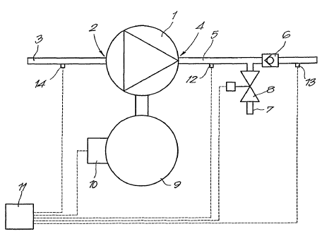
Figure 1 represents a turbocompressor 1 with a suction side
2 onto which is connected a suction line 3, and a delivery
side 4 onto which is connected a compressed air line 5, and
whereby a non-return valve 6 is provided in this compressed
air line 5 which prevents a flow towards the
turbocompressor 1.
The above-mentioned non-return valve 6 is in this case
built in the conventional manner with a spring pressing a
sealing element against a seating, but it is not excluded
according to the invention for this non-return valve 6 to
be realised in other ways, such as in the shape of a
controlled valve or the like.
Onto the above-mentioned compressed air line 5, between the
turbocompressor 1 and the above-mentioned non-return valve
6, is also connected an exhaust line 7 with an exhaust
valve 8.
CA 02673764 2009-06-25
WO 2008/138075 PCT/BE2008/000038
The exhaust valve 8 is in this case made in the shape of a
controllable valve with an adjustable position, but the
latter is not necessary according to the invention,
5 however.
The compressor 1 is driven by a motor 9 which is in this
case made as an electric, speed-controlled motor 9 with a
control module 10, but which can also be made in the shape
10 of any other type of motor, for example a thermal motor.
Further, the compressor 1 is in this case provided with a
controller 11, for example in the shape of a PLC or the
like, which is at least connected to the above-mentioned
control module 10, but which is in this case also connected
to the exhaust valve 8.
The compressor is also provided with a first pressure
reader 12 provided in the compressed air line 5, between
the compressor 1 and the non-return valve 6, and a second
pressure reader 13 which is also provided in the compressed
air line 5, past the above-mentioned non-return valve 6,
such that this second pressure reader 13 measures the
pressure prevailing in the compressed air network or in the
process being fed via this compressed air line 5.
Finally, the compressor 1 in this example also includes a
flow rate reader 14 which is in this case provided in the
suction line 3.
Each of the readers 12 to 14 is connected to the above-
CA 02673764 2009-06-25
WO 2008/138075 PCT/BE2008/000038
11
mentioned controller 11.
The method according to the invention is very simple and as
follows.
Under stable working conditions, in other words outside the
surge area, i.e. in the normal working zone as illustrated
by means of the shaded zone A in the diagram of figure 2,
the turbocompressor 1 is preferably adjusted by controlling
the speed of the motor 9 and thus the rotational speed of
the compressor.
The vertical axis in the graph of figure 2 represents the
compression ratio c over the turbocompressor 1, whereas the
horizontal axis represents the compressor flow rate q.
According to the invention, as soon as one or several
process parameters exceed a predetermined limit, the
rotational speed of the turbocompressor 1 will be very
suddenly reduced to a predetermined minimum rotational
speed, and the above-mentioned non-return valve 6 will be
closed.
In this example, when the flow rate as measured by the flow
rate reader 14 drops to or beneath a predetermined minimum
flow rate value corresponding to the surge control curve,
the rotational speed of the turbocompressor 1 will be
reduced very suddenly to a predetermined minimum rotational
speed according to the invention, as represented in the
diagram of figure 2 by the operational point B, outside the
normal working zone A.
CA 02673764 2009-06-25
WO 2008/138075 PCT/BE2008/000038
12
The above-mentioned minimum flow rate value and the minimal
rotational speed can hereby be stored for example in the
above-mentioned controller 11 and can be determined
experimentally for example to obtain the best results.
According to a preferred characteristic of a method
according to the invention, combined with the sudden
reduction of the rotational speed and the sealing of the
non-return valve 6, the exhaust valve 8 is opened, such
that the compressor 1 is isolated from the process.
As the compressor 1 turns at a very low rotational speed
while the exhaust valve 8 is open, the pressure ratio over
the compressor 1 is low and the compressor 1 consumes only
a limited compressor power.
Thanks to the low rotational speed, the losses occurring
for example in the bearings of the motor 9 and the
compressor 1 and in the possible transmission between the
motor 9 and the compressor 1 are much smaller than in
nominal operation.
The conditions under which the normal operating conditions
are reassumed, in other words under which the rotational
speed of the compressor is increased again and the exhaust
valve 8 is sealed, whereas the non-return valve opens again
due to the increasing pressure on the compressor side of
said non-return valve 6, are programmed in the controller
11 as well.
CA 02673764 2009-06-25
WO 2008/138075 PCT/BE2008/000038
13
An example of such a switch-back condition may be for
example that the pressure value of the process or the
compressed air network, measured by the second pressure
reader 13, drops under a certain value.
According to a special characteristic of the invention, the
exhaust valve 8 may be adjustable between a number of
different positions, or said exhaust valve 8 may even be
adjustable in a continuously variable manner, such that,
when the measured flow rate drops to the above-mentioned
minimum flow rate value, said exhaust valve 8 is first
opened in a controlled manner by means of a modulating
control.
Should a stop condition occur in this case, for example
when a predetermined opening of the exhaust valve 8 is
reached, the above-mentioned steps of the method according
to the invention may start, namely the sudden reduction of
the rotational speed, the opening of the exhaust valve 8
and the closing of the non-return valve 6.
According to the invention, it is not excluded for the
above-mentioned method to be combined with the application
of adjustable inlet vanes, adjustable diffusion vanes,
throttling the suction line or other adjusting means making
it possible to adjust the supplied compressor flow rate.
In the above-described example, use is made of an exhaust
valve 8, but the presence of such an exhaust valve is not
strictly necessary and it can be omitted or combined and/or
replaced by a return line to divert an amount of compressed
CA 02673764 2009-06-25
WO 2008/138075 PCT/BE2008/000038
14
gas.
The present invention can be applied to all types of
turbocompressors, i.e. on axial as well as on radial
turbocompressors.
According to a special characteristic of the invention, the
above-mentioned compressor 1 is composed of several
compressor stages, whereby these compressor stages are
either:
a) driven by a single motor; or
b) are driven by several motors, either or not having the
same nominal and reduced rotational speed values.
In the latter case, when there are several motors, the
rotational speed of the different above-mentioned motors
can be either or not simultaneously reduced.
If required, in each of the above-mentioned cases a) and
b), one or several exhaust valves can be provided between
the different compressor stages and/or after the final
compressor stage.
The present invention is by no means restricted to the
method described as an example and represented in the
drawings; on the contrary, such a method according to the
invention can be made in many ways while still remaining
within the scope of the invention.