Language selection

Search

Patent 2674126 Summary

Third-party information liability

Some of the information on this Web page has been provided by external sources. The Government of Canada is not responsible for the accuracy, reliability or currency of the information supplied by external sources. Users wishing to rely upon this information should consult directly with the source of the information. Content provided by external sources is not subject to official languages, privacy and accessibility requirements.

Claims and Abstract availability

Any discrepancies in the text and image of the Claims and Abstract are due to differing posting times. Text of the Claims and Abstract are posted:

  • At the time the application is open to public inspection;
  • At the time of issue of the patent (grant).
(12) Patent: (11) CA 2674126
(54) English Title: GUIDE DEVICE FOR THE CHOCKS OF WORK ROLLS
(54) French Title: DISPOSITIF DE GUIDAGE POUR LES PIECES D'INSERTION DE CYLINDRES DE TRAVAIL
Status: Deemed expired
Bibliographic Data
(51) International Patent Classification (IPC):
  • B21B 31/02 (2006.01)
(72) Inventors :
  • FILK, EDGAR (Germany)
  • ZETZSCHE, HEIKO (Germany)
  • GIESLER, OTMAR (Germany)
  • BERENDES, ANDREAS (Germany)
  • TIEPELMANN, BERND (Germany)
(73) Owners :
  • SMS SIEMAG AKTIENGESELLSCHAFT (Germany)
(71) Applicants :
  • SMS SIEMAG AKTIENGESELLSCHAFT (Germany)
(74) Agent: SMART & BIGGAR IP AGENCY CO.
(74) Associate agent:
(45) Issued: 2013-04-02
(86) PCT Filing Date: 2007-11-27
(87) Open to Public Inspection: 2008-07-10
Examination requested: 2009-10-14
Availability of licence: N/A
(25) Language of filing: English

Patent Cooperation Treaty (PCT): Yes
(86) PCT Filing Number: PCT/DE2007/002144
(87) International Publication Number: WO2008/080376
(85) National Entry: 2009-06-30

(30) Application Priority Data:
Application No. Country/Territory Date
10 2007 001 322.3 Germany 2007-01-03

Abstracts

English Abstract


The invention relates to a guiding device for the chocks of work rolls
of a rolling stand comprising guides (6, 7, 8, 9) arranged fixedly or
horizontally
movably on the inner sides of the windows of the rolling stand, wherein the
upper
and lower bending blocks (2, 3, 4, 5) of each side are respectively assigned
two
guides (6, 7, 8, 9) arranged parallel to each other. The aim of the invention
is to
simplify the guidance for the bending blocks. For this purpose, it is proposed
that
each bending block (2-5) is assigned one of the guides (6-9), while it has a
recess
(10) for the parallel running guide that extends around said guide, wherein
the
upper bending block (2, 4) is guided on one of the parallel guides (7, 8) and
the
lower bending block (3, 5) is guided on the other guide (6, 9).


French Abstract

L'invention concerne un dispositif de guidage pour les pièces d'insertion de cylindres de travail d'une cage de laminoir, avec des guides (6, 7, 8, 9) disposés fixement ou à déplacement horizontal sur les côtés intérieurs des fenêtres de la cage de laminoir. Deux guides (6, 7, 8, 9) disposés parallèlement entre eux sont respectivement associés au bloc de cintrage supérieur et au bloc de cintrage inférieur (2, 3, 4, 5) de chaque côté. L'invention vise à simplifier le guidage pour les blocs de cintrage. À cet effet, un des guides (6 à 9) est associé à chaque bloc de cintrage (2 à 5) et il présente un évidement (10) pour le guide s'étendant en parallèle, évidement qui s'engage autour de ce dernier. Le bloc de cintrage supérieur (2, 4) est guidé sur l'un des guides parallèles (7, 8), et le bloc de cintrage inférieur (3, 5) sur l'autre guide (6, 9).

Claims

Note: Claims are shown in the official language in which they were submitted.


CLAIMS:
1. A guide device for the chocks of work rolls of a rolling stand with guides
arranged in a stationary or horizontally movable manner on the inner sides of
the
windows of the rolling stand, where two guides, which are arranged parallel to
each
other, are assigned to upper and lower bending blocks of each inner side,
wherein
one of the guides is assigned to each bending block, wherein the guide device
comprises a recess for the guide, by which recess the guide is enclosed, and
wherein
the upper bending block is guided on one of the guides the lower bending block
on
another guide.

2. A guide device according to claim 1, wherein bushes are provided as
plain bearings in the upper and lower bending blocks.

3. A guide device according to any one of claims 1 or 2, wherein slide
plates are provided as antitwist devices on a front of a rear bracket.

4. A guide device according to any one of claims 1 to 3, wherein the
guides are designed as round guides.

5. A guide device according to any one of claims 1 to 4, wherein the
guides are attached to the rolling stand by a bracket.

6. A guide device according to any one of claims 1 to 5, wherein the guide
device is provided with a horizontal shift system.


Description

Note: Descriptions are shown in the official language in which they were submitted.


CA 02674126 2012-04-25
20337-633

GUIDE DEVICE FOR THE CHOCKS OF WORK ROLLS

The present invention pertains to a guide device for the chocks of work
rolls of a rolling stand with guides arranged in a stationary or horizontally
movable
manner on the inner sides of the windows of the rolling stand, where two
guides,
which are arranged parallel to each other, are assigned to the upper and the
lower
bending blocks of each side.

Examples of these types of guide devices are disclosed in
DE 39 06 618 C2 and in EP 768 125 131.

In DE 39 06 618 C2, holding pieces are provided, each of which holds
two pairs of guides, where the bending blocks for the upper and lower chocks
are
guided on these guides. Guide tubes, bushes, or comparable elements located at
the ends of the bending blocks are provided for this guidance. To prevent
twisting,
each bending block has a guide bore, which is also provided with a guide
element.

In the solution known from EP 768 125 131, rods or cylindrical bars are
used as guides instead of tubes.

Some embodiments of the invention may simplify the guidance of the
bending blocks and especially may avoid or of significantly reduce the
friction which
occurs in the other known systems.

According to some embodiments of the invention, there is provided a
guide device for the chocks of work rolls of a rolling stand with guides
arranged in a
stationary or horizontally movable manner on the inner sides of the windows of
the
rolling stand, where two guides, which are arranged parallel to each other,
are
assigned to upper and lower bending blocks of each inner side, wherein one of
the
guides is assigned to each bending block, wherein the guide device comprises a
recess for the guide, by which recess the guide is enclosed, and wherein the
upper
bending block is guided on one of the guides the lower bending block on
another
guide.

1


CA 02674126 2012-04-25
20337-633

What is involved here is a system which works like the roll-bending
system with bending blocks (guide pieces) known from the past. Different in
principle, however, is the way in which the bending blocks are guided. This
serves to
achieve a significant reduction in the amount of friction in the system.

It is also true in the inventive solution that two guides are provided per
guide device, but each bending block comprises only one tube, which holds two
antifriction bushes, so that it is this guide which actually provides the
guidance. A
recess is provided in this bending block for the second guide. In the case of
the
other, cooperating bending block, this guide -- for which an opening has been
provided in the previously mentioned bending block -- then serves as the
actual
guide, whereas an opening is provided there for the other guide. As a result,
only
one of the guides of the guide device is used for the guidance of each bending
block.

Bushes can be provided as plain bearings in the bending blocks.
Slide plates can be provided on the front side of the rear bracket to
prevent twisting.

The guides can be designed as round guides.

The guides themselves are preferably attached to the rolling stand by
means of brackets.

Finally, the guide device can be provided with a horizontal shift system.
The inventive solution is to be explained in greater detail below by
reference to the drawings:

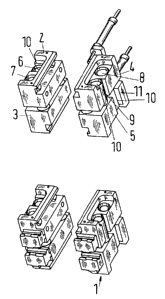
Figure 1 shows a perspective view of the four bending blocks,
2


CA 02674126 2012-04-25
20337-633

Figure 2 shows a side view in partial cross section,
Figure 3 shows a bracket for the guide rods in detail, and

Figure 4 shows an exemplary embodiment of the horizontal shift system.

For the sake of simplicity, only the parts which are necessary to understand
the invention
are shown in the diagrams of the inventive solution.

The bending system consists of four units 1, each with 2 bending blocks 2, 3
and 4, 5, and
a bracket 20.

There are two guide rods 6, 7; 8, 9 per bracket, which is attached to the
rolling stand, for
example. One bending block is guided on each of the guide rods 6, 7; namely,
the upper bending
block 2 on one side is guided on the guide 7, whereas the lower bending block
3 on this same
side is guided on the guide 6. In a corresponding manner, the upper bending
block 4 on the other
side is guided on the guide 8, and the lower bending block 5 is guided on the
guide 9. In the case
of the one bending block 2, then, a recess 10 is provided for the other guide
6. A

corresponding opening in the lower guide block 3 on this side then partially
encloses the guide 7.
The same applies to the bending blocks on the other side.

Another special feature contrasting with earlier designs is the length of the
guide.
Bushes, serving as plain bearings, are seated in the bending block, and slide
strips 11 are
provided on the bracket 20 to prevent twisting.

In the exemplary embodiment shown here, two bending cylinders 12, the heads 13
of
which act on the upper bending block, are seated in the lower bending block. A
design with a
cylinder is also possible. The rear bracket 20 serves also as a vertical stop
for the movements of
the cylinder.

The contours of the work roll chocks are designed in such a way that that the
line of
3


CA 02674126 2009-06-30

application of the bending cylinders is as close as possible to the center of
the bearing. This
results in a contour different from that of the previous design, but
nevertheless the advantages of
rapid roll replacement remain preserved.

The bending system can be used in the conventional design or in conjunction
with
mechanisms for the horizontal shift (HS) of the work rolls. In both cases, the
system can be
combined with axial displacement mechanisms (CVC, EDC, etc.).

Figure 3 shows the bracket 20 for the guide rods, in this case rods 6 and 7,
on a magnified
scale.

Finally, Figure 4 shows an exemplary embodiment of the horizontal shift system
based
on the example of the guide rods 6 and 7. This is accomplished here by the use
of wedge
surfaces 14 and 15 and a shift drive 16.

4

Representative Drawing
A single figure which represents the drawing illustrating the invention.
Administrative Status

For a clearer understanding of the status of the application/patent presented on this page, the site Disclaimer , as well as the definitions for Patent , Administrative Status , Maintenance Fee  and Payment History  should be consulted.

Administrative Status

Title Date
Forecasted Issue Date 2013-04-02
(86) PCT Filing Date 2007-11-27
(87) PCT Publication Date 2008-07-10
(85) National Entry 2009-06-30
Examination Requested 2009-10-14
(45) Issued 2013-04-02
Deemed Expired 2019-11-27

Abandonment History

There is no abandonment history.

Payment History

Fee Type Anniversary Year Due Date Amount Paid Paid Date
Application Fee $400.00 2009-06-30
Request for Examination $800.00 2009-10-14
Maintenance Fee - Application - New Act 2 2009-11-27 $100.00 2009-10-23
Maintenance Fee - Application - New Act 3 2010-11-29 $100.00 2010-10-22
Maintenance Fee - Application - New Act 4 2011-11-28 $100.00 2011-10-24
Maintenance Fee - Application - New Act 5 2012-11-27 $200.00 2012-10-24
Final Fee $300.00 2013-01-14
Maintenance Fee - Patent - New Act 6 2013-11-27 $200.00 2013-11-18
Maintenance Fee - Patent - New Act 7 2014-11-27 $200.00 2014-11-19
Maintenance Fee - Patent - New Act 8 2015-11-27 $200.00 2015-11-16
Maintenance Fee - Patent - New Act 9 2016-11-28 $200.00 2016-11-15
Maintenance Fee - Patent - New Act 10 2017-11-27 $250.00 2017-11-13
Maintenance Fee - Patent - New Act 11 2018-11-27 $250.00 2018-11-19
Owners on Record

Note: Records showing the ownership history in alphabetical order.

Current Owners on Record
SMS SIEMAG AKTIENGESELLSCHAFT
Past Owners on Record
BERENDES, ANDREAS
FILK, EDGAR
GIESLER, OTMAR
TIEPELMANN, BERND
ZETZSCHE, HEIKO
Past Owners that do not appear in the "Owners on Record" listing will appear in other documentation within the application.
Documents

To view selected files, please enter reCAPTCHA code :


To view images, click a link in the Document Description column. To download the documents, select one or more checkboxes in the first column and then click the "Download Selected in PDF format (Zip Archive)" or the "Download Selected as Single PDF" button.

List of published and non-published patent-specific documents on the CPD .

If you have any difficulty accessing content, you can call the Client Service Centre at 1-866-997-1936 or send them an e-mail at CIPO Client Service Centre.


Document
Description 
Date
(yyyy-mm-dd) 
Number of pages   Size of Image (KB) 
Representative Drawing 2009-09-22 1 10
Abstract 2009-06-30 1 19
Claims 2009-06-30 1 33
Drawings 2009-06-30 3 74
Description 2009-06-30 4 136
Cover Page 2009-10-08 2 50
Description 2011-05-27 4 139
Claims 2011-05-27 1 33
Description 2012-04-25 4 137
Claims 2012-04-25 1 30
Abstract 2012-09-06 1 19
Cover Page 2013-03-12 2 50
PCT 2010-07-27 1 46
PCT 2009-06-30 6 245
Assignment 2009-06-30 4 118
Prosecution-Amendment 2009-10-14 1 48
Prosecution-Amendment 2010-11-30 3 79
Prosecution-Amendment 2011-05-27 6 230
Prosecution-Amendment 2011-10-25 3 87
Prosecution-Amendment 2012-04-25 7 295
Correspondence 2013-01-14 2 63