Note: Descriptions are shown in the official language in which they were submitted.
CA 02674299 2011-09-02
LOW SPEED PULSATING SHOWERHEAD
BACKGROUND OF THE INVENTION
Field of the Invention
The present invention relates generally to showerheads, and more specifically
to
pulsating showerheads.
Background Art
Generally, showerheads are used to direct water from the home water supply
onto a user
for personal hygiene purposes. Showers may provide an alternative to bathing
in a bath tub.
5 In the past, bathing was the overwhelmingly popular choice for personal
cleansing.
However, in recent years showers have become increasingly popular for several
reasons. First,
showers generally take less time than baths. Second, showers generally use
significantly less
water than baths. Third, shower stalls and bath tubs with showerheads are
typically easier to
maintain. Fourth, showers tend to cause less soap scum build-up.
With the increase in popularity of showers has come an increase in showerhead
designs
and showerhead manufacturers. Many showerheads, for example, may emit
pulsating streams of
water in a so-called "massage" mode. Yet others are referred to as "drenching"
showerheads,
since they have relatively large faceplates and emit water in a steady, soft
spray pattern.
BRIEF SUMMARY OF THE INVENTION
5 Various embodiments of a showerhead may include a housing, a turbine, and a
shutter.
The housing may define a chamber in fluid communication with a fluid inlet and
at least one
fluid outlet. The turbine may be received within the chamber. The shutter may
be received
within the chamber and operatively associated with the turbine. Rotation of
the turbine may
1
CA 02674299 2009-06-29
WO 2008/083229 PCT/US2007/088962
Eunomey Locxe1 1V o. 16 i Osu4/rL I
cause rotation of the shutter. A rotation rate of the shutter may be less than
a rotation rate of the
turbine. As the shutter rotates, the shutter may fluidly connect and
disconnect the fluid inlet and
the at least one fluid outlet.
In some showerhead embodiments, the housing may include a first engagement
feature,
the shutter may include a second engagement feature, and engagement of the
first engagement
feature with the second engagement feature may cause the rotation rate of the
shutter to be less
than the rotation rate of the turbine. The first engagement feature, the
second engagement
feature, or both, may be at least one gear tooth.
In yet further showerhead embodiments, the shutter may include at least one
opening, and
the at least one opening may fluidly connect and disconnect the fluid inlet
and the at least one
fluid outlet. In yet more showerhead embodiments, the shutter may include a
disk and an integer
number of first features distributed around a periphery of the disk, the
housing may include an
integer number of second features incorporated within an inner surface of the
housing defining
the chamber, the number of first features may be different than the number of
second features,
5 and rotation of the shutter may selectively engage the first features with
the second features.
BRIEF DESCRIPTION OF THE DRAWINGS
Fig. 1 depicts a perspective view of a first embodiment of a showerhead.
Fig 2 depicts another perspective view of the showerhead shown in Fig. 1.
Fig. 3 depicts a cross-section view of the showerhead shown in Fig. 1, viewed
along line
3-3 in Fig. 2.
Fig. 4 depicts an exploded perspective view of the showerhead shown in Fig. 1.
Fig. 5 depicts another exploded perspective view of the showerhead shown in
Fig. 1.
Fig. 6 depicts another cross-section view of the showerhead shown in Fig. 1,
viewed
along line 6-6 in Fig. 3.
5 Fig. 7 depicts yet another cross-section view of the showerhead shown in
Fig. 1, viewed
along line 7-7 in Fig. 3.
Fig. 8 depicts still yet another cross-section view of the showerhead shown in
Fig. 1,
showing a view similar to the view shown in Fig. 7.
2
CA 02674299 2009-06-29
WO 2008/083229 PCT/US2007/088962
ttLLV1110y 11UL M;L INV. 10/ OV''/rl. I
Fig. 9 depicts a cross-section view of the showerhead shown in Fig. 1 similar
to the view
shown in Fig. 8, showing the position of the shutter openings relative to the
showerhead outlets
after the turbine has moved one complete revolution from the position shown in
Fig. 8.
Fig. 10 depicts a cross-section view of the showerhead shown in Fig. 1 similar
to the
view shown in Fig. 8, showing the position of the shutter openings relative to
the showerhead
outlets after the turbine has moved two complete revolutions from the position
shown in Fig. 8.
Fig. 11 depicts a cross-section view of the showerhead shown in Fig. 1 similar
to the
view shown in Fig. 8, showing the position of the shutter openings relative to
the showerhead
outlets after the turbine has moved three complete revolutions from the
position shown in Fig. 8.
Fig. 12 depicts yet a further cross-section view of the showerhead shown in
Fig. 1,
showing a view similar to the view shown in Fig. 7 and showing the cam in a
first position.
Fig. 13 depicts a cross-section view of the showerhead shown in Fig. 1 similar
to the
view shown in Fig. 12, showing the cam in a second position and the
relationship of the
perimeter of the shutter to the housing when the cam is in the second
position.
5 Fig. 14 depicts a cross-section view of the showerhead shown in Fig. 1
similar to the
view shown in Fig. 12, showing the cam in a third position and the
relationship of the perimeter
of the shutter to the housing when the cam is in the third position.
Fig. 15 depicts a cross-section view of the showerhead shown in Fig. 1 similar
to the
view shown in Fig. 12, showing the cam in a fourth position and the
relationship of the perimeter
of the shutter to the housing when the cam is in the fourth position.
Fig. 16 depicts a perspective view of a second embodiment of a showerhead.
Fig. 17 depicts another perspective view of the showerhead shown in Fig. 16.
Fig. 18 depicts a cross-section view of the showerhead shown in Fig. 16,
viewed along
line 18-18 in Fig. 16.
i Fig. 19 depicts an exploded perspective view of the showerhead shown in Fig.
16.
Fig. 20 depicts another exploded perspective view of the showerhead shown in
Fig. 16.
3
CA 02674299 2009-06-29
WO 2008/083229 PCT/US2007/088962
Ar[omey liocxei iNo. i 2S i uu4iru i
Fig. 21 depicts another cross-section view of the showerhead shown in Fig. 1,
viewed
along line 21-21 in Fig. 18.
Fig. 22 depicts a cross-section view of the showerhead shown in Fig. 16
similar to the
view shown in Fig. 21, showing the position of the shutter opening relative to
the housing after
rotation of the shutter within the housing.
Fig. 23 depicts a top view of the housing for the showerhead shown in Fig. 25.
Fig. 24 depicts a top view of the shutter for the showerhead shown in Fig 16.
Fig. 25 depicts a bottom view of the turbine for the showerhead shown in Fig.
16.
Fig. 26 depicts a top view of another housing for the showerhead shown in Fig.
16.
Fig. 27 depicts another cross-section view of the showerhead shown in Fig. 16
similar to
the view shown in Fig. 18, showing another shutter for the showerhead shown in
Fig. 16
positioned within the housing shown in Fig. 26.
DETAILED DESCRIPTION
Described herein are showerheads for generating a relatively low speed
pulsating spray.
5 The showerheads may include a jet disk, a turbine, a shutter, and a housing.
Water flowing
through the showerhead causes the turbine to spin. As the turbine spins, it
rotates the shutter.
The shutter may be configured to rotate at a slower speed than the turbine to
produce a periodic
interruption of water flow through outlets or nozzles defined in, or attached
to, the housing to
create a pulsating spray. This pulsating spray may simulate the feel of a hand
massage.
The shutter may take the form of a generally circular disk including gear
teeth that
selectively engage gear teeth in the housing. The turbine may include an
offset cam that drives
the shutter. The speed reduction achieved is the ratio of the difference in
the number of gear
teeth of the housing and the shutter to the number of gear teeth on the
shutter. Expressed
mathematically, this may be written as: (Housing Teeth-Shutter Teeth)/(Shutter
Teeth).
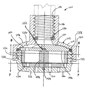
5 Figs. 1-15 depict various views of a first embodiment of a showerhead 100.
With
reference to Figs. 1 and 2, the showerhead 100 may include a housing 102. The
housing 102
may be formed from upper and lower housing portions 104, 106. The upper
housing portion 104
may include a fluid inlet for receiving fluid from a fluid source. The upper
housing portion 104
may further include threads 108 proximate the fluid inlet for threadedly
joining the showerhead
4
CA 02674299 2009-06-29
WO 2008/083229 PCT/US2007/088962
HLLUillcy uuel wL IN U. 10 / I
100 to a shower pipe, flexible arm, hose connector, arm assembly, or other
device for conveying
fluid, such as water, (i.e., a fluid source) to the showerhead 100. Although
shown as threadedly
joined to the fluid conveying device, the showerhead 100 may be attached to
the fluid conveying
device using any known connection method or combination of methods, including,
but not
limited to, press fitting, clamping, welding, and so on. The lower housing
portion 106 may
include one or more fluid outlets 110 in selective fluid communication with
the fluid inlet. The
fluid outlets 110 may be generally circular holes or any other suitably shaped
hole or opening. A
fluid, such as water, may be delivered from a fluid source to a user via the
showerhead 100
through at least one of the fluid outlets 110.
The upper housing portion 104, the lower housing portion 106, or both portions
may
include user engagement features to facilitate joining the portions. For
example, the upper and
lower portions 104, 106 as shown in Figs. 1 and 2 may each include recessed
surfaces 112, 114
for providing a surface for a user to grip. In other embodiments, the upper
housing portion 104,
the lower housing portion 106, or both may incorporate other types of user
engagement features,
i or combinations of features, such as raised protrusions, tabs, roughened
surfaces, and so on, that
may enhance a user's grip on the upper housing portion 104, the lower housing
portion 106, or
both portions for joining the portions, moving the showerhead 100 relative to
a shower pipe or
other device for conveying fluid to the showerhead, and/or selecting a
showerhead operating
mode.
Turning to Figs. 3-5, the upper housing portion 104 may include a generally
cylindrical
housing shaft 116 defining a fluid passage. The fluid passage may be in fluid
communication
with the fluid inlet. A generally annular housing flange 118 may extend
radially outward from a
lower portion of the housing shaft 116. A generally circular upper housing
sidewall 120 may
extend generally downward from the housing flange 118. An inner surface of the
upper housing
> sidewall 120 may include threads for joining the upper housing portion 104
to the lower housing
portion 106. A flow restrictor (not shown), as known in the art, may be
positioned in the fluid
passage to limit fluid flow through the showerhead 100 from a fluidly
connected fluid source.
The lower housing portion 106 may include a generally circular lower housing
base 122.
A generally circular lower housing sidewall 124 may extend upward from the
lower housing
5
CA 02674299 2009-06-29
WO 2008/083229 PCT/US2007/088962
Attorney Docket No. 16 /&)4/YU1
base 122. An external surface of the lower housing sidewall 124 may include
threads configured
to engage the upper housing threads.
The upper and lower housing threads may be engaged to join the upper housing
portion
104 to the lower housing portion 106. Although the upper housing threads are
shown as internal
threads and the lower housing threads are shown as external threads, the upper
housing threads
could be external and the lower housing threads could be internal. Further,
the upper and lower
housing portions 104, 106 may be joined by any known connection method,
including, but not
limited to, press fitting, clamping, welding, the aforementioned threading,
and so on.
The upper housing portion 104 and the lower housing portion 106 may define a
chamber
3 or cavity 126. The chamber or cavity 126 may be defined by the upper housing
flange 118, the
lower housing sidewall 124, and the lower housing base 122. The chamber or
cavity 126 may be
generally cylindrical in shape or any other desired shape. The chamber or
cavity 126 may be in
fluid communication with the upper housing fluid passage and in selective
fluid communication
with the fluid outlets 110.
5 Although the shape and configuration of the upper and lower housing portions
104, 106
are described and shown with a certain particularity, the upper and lower
housing portions 104,
106 may take the form of any desired shape to define the exterior and the
interior of the housing
102. Further, the housing 102 may be formed from more or less than two housing
portions. Yet
further, although the housing 102 is shown as including one fluid inlet, one
fluid passage, and
D one chamber or cavity, the housing may include or define more than one of
any of these
elements. For example, the housing 102 may define two fluid inlets, two fluid
passages, and/or
two chambers or cavities. The foregoing example is merely illustrative and is
not intended to
imply for the housing 102 any particular number or arrangement of fluid
inlets, fluid passages, or
chambers or cavities.
5 With continued reference to Figs. 3-5, the showerhead 100 may further
include a jet disk
130, a turbine 132, a shutter 134, and one or more sealing members 136, 138.
The jet disk 130,
the turbine 132, and the shutter 134 may be received within the cavity or
chamber 126 defined by
the housing 102. A fluid source seal member 136 maybe positioned within the
fluid inlet of the
6
CA 02674299 2011-09-02
upper housing portion 104, and a housing seal member 138 may be positioned
between the upper
and lower housing portions 104, 106 proximate the area where these portions
are joined.
The jet disk 130 may include a generally circular and planar body or any other
suitably
shaped body. The jet disk 130 may include one or more jet disk fluid jets or
openings 140.
Although three jets 140 are shown in Figs. 4 and 5, the jet disk 130 may
include more or less
than three jets. Each jet 140 may extend from an upper to a lower surface 142,
144 of the jet
disk 130, thus creating a path for fluid to flow from the jet disk's upper
surface 142 to its lower
surface 144. Further, the jets 140 may be angled relative to the jet disk's
upper and lower
surfaces 142, 144 to impart a directional flow to fluid passing through them.
Such directional
flow may cause the turbine 132 to rotate within the showerhead cavity 126. The
jets 140 may
also be shrouded, which may increase the fluid's flow speed. Alternative
embodiments may vary
the number of jets 140 employed and/or the shrouding configuration.
The turbine 132 may take the form of a generally hollow open-ended cylinder
with blades
146 extending radially inward toward a central hub 148 from a generally
circular turbine wall
> 150. The turbine wall 150, or at least a portion of the turbine wall 150,
may be omitted in some
embodiments. Further, the number of blades 146 may be more or less than the
number depicted
in the figures. The turbine 132 may include a first pin-shaped extrusion 152
extending generally
upward from its upper side and a second pin-shaped extrusion 154 extending
generally
downward from its lower side. Each pin-shaped extrusion 152, 154 may be
located along a
central axis of the turbine 132. The lower pin-shaped extrusion 154 may be
received in an
opening 156 in the housing 102 and the upper pin-shaped extrusion 152 may be
received in an
opening 158 in the jet disk 130. The turbine 132 may rotate about its central
axis (i.e., about the
pin-shaped extrusions 152, 154). Alternatively, the turbine 132 may have an
upper opening that
receives a pin shaped extrusion extending from a lower side of the jet disk
130 and a lower
i opening that receives a pin shaped extrusion extending from the housing 102.
The turbine 132 may include an eccentric cam 160 on its lower side (i.e., the
side facing
the shutter 134). The shutter 134 may take the form of a generally circular
and planar body or
any other desired shape and may include an opening 162 along its central axis
to receive the
eccentric cam 160. The shutter 134 may thus spin about the central axis of the
eccentric cam 160
7
CA 02674299 2009-06-29
WO 2008/083229 PCT/US2007/088962
Attorney Docket No. 18 /8U4/PUT
as the turbine 132 rotates. The center of the eccentric cam 160 is off-center
with respect to the
center axis of the turbine 132 and housing 102. Thus, as the turbine 132
spins, the eccentric cam
160 moves the center of the shutter 134 in a generally circular path around
the center axis of the
turbine 132 and the housing 102. As the center of the shutter 134 moves in
this generally
circular path, the portion of its perimeter that engages or otherwise contacts
the lower housing
portion's side wall 124 changes as shown, for example, in Figs. 12-15.
The shutter body 164 may include one or more fluid openings 166, 168 through
its
thickness for water to pass from the upper side 170 to the lower side 172 of
the shutter 134. The
shutter fluid openings 166, 168 may be selectively aligned with at least some
of the outlets 110
in the housing 102. When aligned, water or other fluid may flow from the
housing chamber or
cavity 126 and out of the outlets 110 aligned with the shutter fluid openings
166, 168. The
shutter 134 may include an engagement feature 174, which may take the form of
gear teeth or the
like. The gear teeth may be, although not necessarily, uniformly distributed
around the shutter
body's periphery.
5 The housing 102 may include a housing engagement feature 176 to engage the
shutter's
engagement feature. The housing engagement feature may be engaging teeth
complementary to
the shutter's gear teeth. These may be, but not necessarily, equally spaced
around the interior
periphery of the lower housing portion 106. As shown, for example, in Fig. 7,
the shutter 134
may include fifteen gear teeth, and the housing 102 may include sixteen
housing teeth. Other
embodiments may use a different number of gear teeth for the shutter 134
and/or housing 102.
At least some of the shutter's gear teeth may engage the housing's gear teeth.
Further, as the
turbine 132 rotates, the gear teeth of the shutter 134 that engage the gear
teeth of the housing 102
may change.
Returning to Figs. 3-5, the fluid source seal member 136 may form a fluid seal
between
5 the showerhead 100 and a fluid source joined to the showerhead 100. More
particularly, the
fluid source seal member 136 may substantially limit or otherwise prevent
fluid leakage from the
showerhead 100 along the threaded joint that joins that fluid source to the
showerhead 100. The
housing seal member 138 may form a fluid seal between the upper and lower
housing portions
104, 106 to substantially limit or otherwise prevent fluid leakage from the
showerhead 100 along
8
CA 02674299 2009-06-29
WO 2008/083229 PCT/US2007/088962
tiuorney voeicei INO. 1 b i bv4irl, I
the threaded joint that joins the upper housing portion 104 to the lower
housing portion 106. The
fluid source and housing seal members 136, 138 may take the form of O-rings or
any other
suitable element that provides a fluid seal between two or more members or
components and
may be composed of an elastomeric material, such as rubber, or any other known
fluid sealant
i material.
Operation of the showerhead 100 will now be described with reference to Figs.
3, 6 and
7. Water or other fluid may flow through the fluid inlet from the fluid source
to the jet disk 130.
As water or other fluid passes through the jets 140, it impacts one or more
blades 146 of the
turbine 132, which is situated within the housing 102 between the shutter 134
and the jet disk
130. Water impacting the turbine blades 146 imparts rotational motion to the
turbine 132. As
viewed from the side of the turbine 132 facing the shutter 134 as shown, for
example, in Fig. 6,
the turbine 132 may rotate in a clockwise fashion. Alternative embodiments may
cause the
turbine 132 to rotate in a counterclockwise fashion. After impacting the
turbine blades 146, the
water hits the upper side 170 of the shutter 134.
As the turbine 132 rotates from water impacting its blades 146, the turbine
132 causes the
center of the shutter 134 to move in a generally circular motion via the
aforementioned
connection between the shutter 134 and the turbine's eccentric cam 160. This
meshes at least
some of the external teeth of the shutter 134 with some of the internal teeth
of the housing 102
resulting in rotational movement of the shutter 134 relative to the turbine
132. Additionally, the
teeth of the shutter 134 and housing 102 disengage at a side of the shutter
134 approximately
opposite the point of engagement as shown, for example, in Fig. 7 and Figs. 12-
15.
Since the shutter 134 has one less tooth than the housing 102 and tooth
disengagement
between the shutter 134 and the housing 102 is made possible by motion of the
center of the
shutter 134 in a generally circular path around the central axis of the
turbine 132, each complete
5 revolution of the turbine 132 results in a one tooth displacement of the
shutter 134 in relation to
the housing 102. This displacement is in the opposite direction of the
rotation of the turbine 132.
For example, if the turbine 132 is rotating in a clockwise direction, the one
tooth displacement of
the shutter 134 relative to the housing 102 will be in a counter-clockwise
direction and vice
versa. Thus, selective engagement of the shutter teeth with the housing teeth
functions as a
9
CA 02674299 2011-09-02
speed reduction mechanism because the shutter 134 rotates 1/15th as quickly as
it would absent
this engagement.
The speed reduction achieved (i.e., how fast the shutter 134 rotates relative
to how fast
the turbine 132 rotates) is determined by the ratio of the difference between
number of
engagement features 176 of the housing 102 to the number of
engagement features 174 on the shutter 134. For the showerhead depicted in
Figs. 1-15, a speed
reduction of 1/15`h occurs since the housing 102 has sixteen gear teeth and
the shutter 134 has
fifteen gear teeth. That is, the shutter 134 rotates at 1/15`h the rotational
speed of the turbine 132.
In other embodiments, the shutter 134 may have 30 gear teeth and the housing
102 may
J have 31 gear teeth. This causes the shutter 134 to turn in the opposite
direction of the turbine
132 by 1/30`h of the rotational rate of the turbine 132. In other words, the
shutter 134 rotates
approximately 1/30`h about its central axis each time the turbine 132
completes one revolution,
and the shutter 134 rotates in the opposite direction of the turbine 132.
Accordingly, the shutter
134 completes a complete revolution in the opposite direction of the turbine
132 each time the
5 turbine 132 completes 30 revolutions. In yet other embodiments, the shutter
134 may have more
engagement teeth than the housing 102, which causes the shutter 134 to rotate
in the same
direction as the turbine 132, albeit at a slower rate. For example, some
embodiments may use a
shutter 134 with thirty gear teeth and a housing 102 with twenty-eight housing
teeth. This causes
the shutter 134 to precess, i.e., turn in the same direction as the turbine
132, at a rate of 1/15th the
J speed of the turbine 132. Other embodiments may employ a shutter 134 and a
housing 102 with
more or fewer teeth to achieve a desired speed reduction and direction of
rotation of the shutter
134 relative to the rotational speed and direction of rotation of the turbine
132.
Referring to Figs. 8-12, as the shutter 134 rotates inside the housing 102,
one or more
shutter fluid openings 166, 168 in the shutter 134 pass over rows of outlets
110 in the housing
5 102. In this manner, water may temporarily flow through the unobstructed
outlets 110 located
under the shutter fluid openings 166, 168. Thus, as the shutter 134 rotates,
water flow through
the outlets 110 is periodically interrupted as the solid portion of the
shutter 134 temporarily
obstructs water flow through outlets 110 located under the solid portion of
the shutter 134 as
depicted, for example, in Figs. 8-12. This creates a pulsating flow of water
from the showerhead
CA 02674299 2009-06-29
WO 2008/083229 PCT/US2007/088962
Attorney Docket No. 18'/8U4/1'( 1
100. The period of the pulsating flow is determined, in part, by the
rotational speed of the
shutter 134 as further explained below.
Fig. 9 generally depicts the shutter 134 rotated clockwise within the housing
102 from the
relative position occupied in Fig. 8 after the turbine 132 has completed one
complete revolution
in a counter-clockwise direction. Fig. 10 generally depicts the shutter 134
rotated clockwise
within the housing 102 from the relative position occupied in Fig. 8 after the
turbine 132 has
completed two complete revolutions in a counter-clockwise direction. Fig. 11
generally depicts
the shutter 134 rotated clockwise within the housing 102 from the relative
position occupied in
Fig. 8 after the turbine 132 has completed three complete revolutions in a
counter-clockwise
direction.
With reference to Figs. 8-12, the shutter 134 may have inner and outer fluid
openings
166, 168 that each extend about half way around the shutter 134. The inner and
outer fluid
openings 166, 168 may generally be formed on opposing halves of the shutter
134. The housing
102 also may include an inner and outer circular row of outlets 110. The inner
fluid opening 168
5 of the shutter may overlap at least part of the inner circular row of
outlets 110, while the outer
fluid opening 166 may overlap at least part of the outer circular row of
outlets 110. When the
shutter fluid openings 166, 168 are positioned over certain outlets 110, water
flows through these
unobstructed outlets 110 to exit the showerhead 100. When an outlet 110 is not
aligned with at
least one of the shutter fluid openings 166, 168, water flow is blocked
through that outlet 110.
Thus, as the shutter 134 rotates, water flow through the outlets 110 may be
interrupted in a
sequence. This may, for example, produce a relatively low speed, periodic
interruption of water
flow through each row of outlets 110.
As previously discussed, for the embodiment depicted in Figs. 1-15, there are
15 gear
teeth on the shutter 134 and 16 gear teeth in the housing 102 causing the
shutter 134 to rotate in a
5 direction opposite the turbine 132 at a rate 1/15th that of the turbine 132.
The period of the
pulsating flow of water through an outlet 110 is a direct multiple of the
speed reduction times the
turbine speed. Thus, if water flow through the showerhead 100 causes the
turbine 132 to spin at
60 revolutions per second, the shutter 134 will rotate at a rate of 4
revolutions per second. This
results in a period of the pulsating flow through an outlet 110 of about 0.25
seconds, which may
11
CA 02674299 2009-06-29
WO 2008/083229 PCT/US2007/088962
Attorney Docket No. 1 8 /2SU4/FC 1
simulate the feel of a hand massage. As yet another example, if the turbine
132 rotates at 50
revolutions per minute and the speed reduction is 1/10th, the shutter 134 will
rotate at a rate of
five revolutions per minute. This results in a period of the pulsating flow
through an outlet 110
of about 0.20 seconds. The foregoing examples are merely illustrative and are
not intended to
imply or require a particular speed reduction, turbine speed, or pulse time.
The aforementioned pulse time represents the period of time for one complete
cycle of
flow through an outlet 110. In other words, the time it takes for water to
start flowing through an
outlet 110, stop flowing through the outlet 110, and then start flowing again
through the outlet
110. The ratio of the amount of time that water flows and does not flow
through an outlet during
a single cycle is a function of the length of the shutter fluid opening. As
the length of the shutter
fluid opening increases, the ratio of the time water flows through the
associated outlet 110 to the
time it does not flow through the outlet 110 increases. For example, if a
shutter fluid opening
has a length that extends approximately one-half of the circumference of the
shutter 134 as
shown, for example, in Figs. 12-15, the ratio of the time water flows through
an outlet 110 to not
5 flowing through the outlet 110 will be approximately 1:1. As another
example, if a shutter fluid
opening has a length that extends approximately one-quarter of the
circumference of the shutter
134, the ratio of the time water flows through an outlet 110 to not flowing
through the outlet 110
will be approximately 1:3. The foregoing examples are merely illustrative and
are not intended
to imply any particular length or ratio of flow time during a single cycle for
a showerhead.
Figs. 16-25 depict various views of a second embodiment of a showerhead 200.
The
second showerhead 200 is similar in structure and operation to the first
showerhead 100 and like
numbers for the second showerhead 200 may be used for similar or like elements
of the first
showerhead 100. Like the first showerhead 100, the second showerhead 200 may
include a
turbine 132, a jet disk 130, a shutter 134 and a housingl02. In this
particular embodiment, the
5 shutter 134 may include one fluid opening 202 that extends about two-thirds
the way around the
shutter 134, as shown, for example, in Figs. 19-20. The showerhead 200 may
also include one or
more seal members 136, 138, such as a fluid inlet seal member 136 and housing
seal member
138 as shown, for example, in Figs. 18-20. The fluid inlet seal member 136 and
the housing seal
member 138 may be similar to the corresponding seal members 136, 138 described
for the first
3 showerhead 100.
12
CA 02674299 2009-06-29
WO 2008/083229 PCT/US2007/088962
tiuomey i)ocxet IN o. i is / oo4/rU i
Like the first embodiment, the housing 102 for the second showerhead 200 may
include
upper and lower housing portions 104, 106 threadedly joined as shown, for
example, in Fig. 18,
or joined by any other known connection method or combination thereof. Also
like the housing
102 for the first showerhead 100, the housing 102 for the second showerhead
200, although
S shown as having a particular shape in the figures, may be formed into any
desired shape and may
be formed from any desired number of portions or components. The housing 102
may include
one row of outlets or nozzles 110 as shown in Fig. 20, which may be fluidly
connected the
housing chamber or cavity 126 via fluid passages or conduits 204 defined in a
base 122 of the
lower housing portion 106 as shown, for example, in Figs. 18 and 19. Each
fluid passage 204, in
turn, may include a fluid passage opening 206 defined in an upper surface of
the base 122 for
fluidly joining the fluid passage to the housing chamber or cavity 126. For a
given sized turbine
132 and/or chamber 126, the fluid conduits allow for the use of a larger
showerhead 200 to create
a larger diameter spray pattern from the showerhead 200.
Like the shutter 134 for the first showerhead 100, the shutter 134 for the
second
i showerhead 200 may include a generally circular and planar (or any other
shaped) body
including at least one shutter fluid opening 202. Also like the shutter 134
for the first
showerhead 100, the shutter 134 for the second showerhead 200 may include a
cam opening 162
along its central axis for receiving an eccentric cam 160 formed on the
turbine 132. The shutter
134 may thus spin or rotate about the central axis of the eccentric cam 160 as
the turbine 132
rotates in a manner similar to the shutter 134 for the first showerhead 100.
As the turbine 132
spins, the motion of the eccentric cam 160 causes the shutter 134 to rotate
about the center of the
eccentric cam 160 such that the portions of the shutter's periphery that
contacts the housing 102
changes as described in more detail above for the first showerhead 100.
The shutter 134 and housing 102 may each include one or more gear teeth, as
described
i above. For example, and as illustrated in Figs 21 and 22, the shutter 134
may have 15 gear teeth
and the housing may have 16 gear teeth that engage the shutter teeth.
Accordingly, the shutter
134 rotates inside the housing 102 in an opposite direction with respect to
the turbine 132 at a
rate 1115th the speed of the turbine 132. Fig. 22 generally depicts the
shutter 134 rotated
clockwise within the housing 102 from its position in Fig. 21.
13
CA 02674299 2009-06-29
WO 2008/083229 PCT/US2007/088962
Attorney Docket No. 187804/PUT
As depicted in Figs. 21 and 22, as the shutter 134 rotates, the flow of water
through the
fluid passage openings 206, and thus the outlet 110 in fluid communication
with a respective
fluid passage opening 206, is interrupted as the solid portion of the shutter
134 passes over a
fluid passage opening 206. When the shutter fluid opening 202 is over a fluid
passage opening
206, water flows through the associated fluid passage 204 and exits the
showerhead 200 through
the outlet 110 associated with the fluid passage 204. When a fluid passage
opening 206 is not
aligned with the shutter fluid opening 202, water flow ceases through the
outlet 110 in fluid
communication with the fluid passage opening 206. Thus, as the shutter 134
rotates, water flow
through the outlets 110 may be interrupted in a sequence. This may, for
example, produce a
relatively low speed, periodic interruption of water flow through each outlet
110. Other
embodiments may employ more or fewer rows of outlets 110 in the housing 102
and may
employ more or fewer shutter fluid openings 202 to create a variety of low
speed pulsating water
flow patterns. As an example, the shutter fluid openings 202 may be radially
aligned with one
another to produce a spray pattern. As another example, the outlets 110 may be
grouped within
5 one or more sectors on the housing base 122 and/or spaced non-uniformly
within one or more
rows.
Water flow through the second showerhead 200, at least to the bottom side of
the shutter
134, generally proceeds as previously described above for the first showerhead
100. Also as
previously described above for the first showerhead 100, selective engagement
of the shutter
engagement feature 174 with the housing engagement feature 176 causes the
shutter 134 to rotate
at a slower speed than the turbine 132. As the shutter 134 rotates inside the
chamber 126 of the
housing 102, one or more shutter fluid openings 202 may pass over one or more
rows of fluid
passage openings 206 in the housing 102. This permits water to temporarily
flow through the
unobstructed fluid passage openings 206. Thus, as the shutter 134 rotates,
water flow through
5 the outlets or nozzles 110 is periodically interrupted as the solid portion
of the shutter 134
temporarily obstructs the water flow through those outlets 110 in fluid
communication with fluid
passage openings 206 located under the solid portion of the shutter 134. This
creates a pulsating
flow of water from the showerhead 200.
Various embodiments of the second showerhead 200 may use the same or differing
numbers of fluid passage openings 206 to outlets or nozzles 110. For example,
each outlet 110
14
CA 02674299 2009-06-29
WO 2008/083229 PCT/US2007/088962
tilwl lii y L/Vl:SGL INV. 10/ 0V'F/r% l
may be in fluid communication with a single fluid passage opening 206, or an
outlet 110 may be
in fluid communication with two or more fluid passage openings 206, or vice
versa.
Other embodiments of the showerhead, including variations of the first and
second
showerheads 100, 200, may use other types of engageable features on the
shutter 134 and the
housing 102 to cause the shutter 134 to rotate at a different rate than the
turbine 132. For
example, the shutter 134 may have external, involute teeth and the housing 102
may have
matching internal, involute housing teeth. As another example, the shutter 134
may have saw
tooth features that mate to saw tooth cuts in the housing 102 as depicted in
Figs. 26 and 27. In
yet another example, circular pins extending radially from the periphery of
the shutter 134 may
mate with slots in the housing 102. As yet another example, slots in the
shutter 134 may mate
with pins extending radially inward from the housing 102. As still yet another
example, circular
cuts in the periphery of the shutter 134 may engage pins in the housing 102.
The foregoing
examples are merely illustrative and are not intended to limit the engageable
features for the
shutter 134 and/or the housing 102 to any particular feature, or to limit
other mechanisms for
> causing the shutter 134 to rotate at different rate than the turbine 132.
Further, the engagement of the shutter 134 to the housing 102 is generally not
limited to
the use of engagement features 174, 176 to implement the speed reduction
mechanism or to
otherwise change the rotational speed of the shutter 134 relative to the
turbine 132. In some
embodiments, the shutter 134 may be made to lag the turbine 132 through
friction engagement
between the shutter 134 and housing 102. In such embodiments, the speed
reduction may be
determined by the ratio of the difference in the diameters of the housing 102
and the shutter 134,
divided by the diameter of the shutter 134 (presuming minimal to no slippage
between the
shutter 134 and the housing 102).
The housing 102, shutter 134, jet disk 130, turbine 132, and other elements
for any
i embodiment of a showerhead may be integrally formed or may be made of two or
more separate
components that are joined together by mechanical fasteners, sonic or heat
welds, adhesives,
chemical bonds, any other suitable method, or any combination thereof.
Further, the components
may be formed from any suitable material, including, but not limited to,
plastics, metals,
elastomers, and so on.
CA 02674299 2009-06-29
WO 2008/083229 PCT/US2007/088962
Ar[omey iIocxet ivo. I Z / 6U4/rU I
All directional references (e.g., upper, lower, upward, downward, left, right,
leftward,
rightward, top, bottom, above, below, vertical, horizontal, clockwise, and
counterclockwise) are
only used for identification purposes to aid the reader's understanding of the
examples of the
invention, and do not create limitations, particularly as to the position,
orientation, or use of the
> invention unless specifically set forth in the claims. Joinder references
(e.g., attached, coupled,
connected, joined and the like) are to be construed broadly and may include
intermediate
members between the connection of elements and relative movement between
elements. As
such, joinder references do not necessarily infer that two elements are
directly connected and in
fixed relation to each other.
In some instances, components are described by reference to "ends" having a
particular
characteristic and/or being connected with another part. However, those
skilled in the art will
recognize that the present invention is not limited to components which
terminate immediately
beyond their point of connection with other parts. Thus the term "end" should
be broadly
interpreted, in a manner that includes areas adjacent rearward, forward of or
otherwise near the
i terminus of a particular element, link, component, part, member or the like.
In methodologies
directly or indirectly set forth herein, various steps and operations are
described in one possible
order of operation but those skilled in the art will recognize the steps and
operation may be
rearranged, replaced or eliminated without necessarily departing from the
spirit and scope of the
present invention. It is intended that all matter contained in the above
description or shown in
the accompanying drawings shall be interpreted as illustrative only and not
limiting. Changes in
detail or structure may be made without departing from the spirit of the
invention as defined in
the appended claims.
16