Note: Descriptions are shown in the official language in which they were submitted.
CA 02674323 2009-07-02
WO 2008/085668
PCT/US2007/087696
1
SURGICAL SYSTEMS AND METHODS FOR BIOFILM REMOVAL,
INCLUDING A SHEATH FOR USE THEREWITH
BACKGROUND
Bacterial biofilms develop in variety of bodily cavities, including those of
the ear,
such as the middle ear, and of the nose, such as the frontal or maxillary
sinuses, for
example. Regardless, the bacteria that generate biofilms often (but not
necessarily) are a
result of inflammatory insult to tissues, including inflammation arising due
to fungi,
temperature and pressure changes, allergens, or other sources. The emergence
of bacterial
growth and associated symptoms is often a cyclical, escalating process with
initiation of
the inflammatory process facilitating increased bacterial production, which,
in turn, causes
more inflammation, and so forth. Once bacterial growth has been established,
the bacteria
will often aggregate, stop dividing, and begin forming protective bacterial
biofilm layers,
or "slime layers," comprised of polysaccharide matrices.
The protective bacterial biofilm interferes with the body's natural immune
response as well as traditional methods of treatment, often times resulting in
chronic,
recurrent infections and associated symptoms. In particular, the bacteria emit
exotoxins,
which incite the body's immune system to respond with white cells. However,
the
bacterial biofilm interferes with the efficacy of the white cells' ability to
attack the
bacteria. The biofilm can also act as a barrier against topical administration
of antibiotics
and other medicaments. Biofilm-forming bacteria also present obstacles to
traditional,
antibiotic treatments that act to kill dividing bacteria. In particular, the
bacteria in a
biofilm-forming state may have already ceased cell division, rendering such
antibiotics
largely ineffective.
For example, relative to chronic rhinosinusitis and other similar ailments,
bacteria
in the nose can be viewed as a continuum. Some bacterias (e.g., certain
strains of
pseudomonas and staph aureus) form robust biofilms. Others (e.g., h. flu) form
relatively
mild biofilms. The biofilms may or may not include or contain fungi. Each of
these
microbes has a somewhat different or complimentary inflammatory pathway and
interacts
with the host's immune system differently. For example, staph aureus produces
a
lipopolysaccharide matrix that acts as an antigen and causes a host response,
as well as
toxins (e.g., staph exotin A and B, toxic shock syndrome toxin 1 and 2) that
can produce
CA 02674323 2009-07-02
WO 2008/085668
PCT/US2007/087696
2
an antigenic and even hyperantigenic (hyperinflammatory) response. Other
microbes can
also produce inflammatory-inciting toxins.
Functional endoscopic sinus surgery (FESS) is a minimally invasive surgical
procedure used to treat sinusitis, an infection of the sinuses. FESS opens up
sinus air cells
and sinus ostia (openings) with an endoscope. The use of FESS as a sinus
surgical method
has now become widely accepted. For reference, the term "functional" is meant
to
distinguish this type of endoscopic surgery from non-endoscopic, more
conventional sinus
surgery procedures.
The purpose of FESS is typically to restore normal drainage of the sinuses,
which
requires ventilation through the ostia. In particular, a muco-ciliary
transport process
maintains a constant flow of mucus out of the sinuses with the hair-like cilia
of a ciliated
epithelium layer acting to direct the flow of mucus toward the ostia. Where
there is
insufficient ventilation or mucous transportation, infection and inflammation
can result, a
condition known as sinusitis. Sinusitis often develops from an infection where
the
maxillary and frontal sinuses meet near the nose or, occasionally, from a
dental infection.
Regardless, sinusitis causes the cilia to work less efficiently and causes the
mucous
membranes of the sinuses to become engorged, resulting in obstruction of the
ostia. The
ensuing lack of ventilation and drainage produce conditions which are ripe for
bacterial
infection, including biofilm-forming bacteria. As described above, such
bacterial biofilms
often interfere with effective treatment of bacterial infections, such as
chronic
rhino sinusitis
With the foregoing background, it has been postulated that effective treatment
of
recurrent, chronic inflammatory diseases, such as sinusitis, including chronic
rhinosinusitis, requires therapies addressing associated bacterial infections
and bacterial
biofilms.
SUMMARY
Some embodiments address a system for removal of bacterial biofilm from a
target
site of a human patient. Some systems include an irrigation duct, a nozzle, an
aspiration
duct, an endoscope, and a removable endoscope sheath. The irrigation duct is
in
communication with a fluid source. The nozzle communicates with the irrigation
duct, the
CA 02674323 2009-07-02
WO 2008/085668
PCT/US2007/087696
3
nozzle positioned to dispense the fluid directly at a target site. The
aspiration duct is in
communication with a vacuum source, the aspiration duct terminating at a
distal inlet for
aspirating fluid dispensed from the nozzle. The endoscope has an elongated
insertion tube
defining a working end adapted to facilitate imaging the target site. The
removable
endoscope sheath provides a barrier over at least a portion of the insertion
tube during
imaging. In particular, at least one of the irrigation duct and the aspiration
duct is
associated with the endoscope sheath.
Other embodiments relate to endoscope sheaths for use in removing bacterial
biofilm from a target site of a human patient. Some sheaths include an
elongated, flexible
outer sleeve adapted to receive an insertion tube of an endoscope. The outer
sleeve
defines a distal end maintaining a viewing window. The sheath also includes an
irrigation
duct formed as an elongated tube having a distal end maintaining a nozzle. The
nozzle is
secured adjacent the viewing window and is oriented to direct a pressurized
stream of fluid
away from the viewing window and directly against a layer of bacterial biofilm
to
mechanically remove the bacterial biofilm without substantially damaging an
underlying
structure of the target site.
Still other embodiments relate to methods of removing bacterial biofilm from a
target site of a human patient. Some methods include providing a system for
removal of
bacterial biofilm from a target site. The system includes an endoscope having
an insertion
tube defining a working end, an irrigation duct connected to a nozzle, an
aspiration duct
having an inlet, and a removable endoscope sheath for covering the insertion
tube. At
least one of the irrigation duct and the aspiration duct is part of the
removable endoscope
sheath. Each of the working end of the endoscope, the inlet of the aspiration
duct, and the
nozzle, respectively, is disposed proximate the target site, the target site
including a layer
of bacterial biofilm adhered to a surface. The target site is imaged with the
working end
of the endoscope. A flow of fluid is dispensed through the nozzle, via the
irrigation duct,
toward the target site to mechanically remove a substantial portion of the
layer of bacterial
biofilm from the surface. The removed bacterial biofilm and the dispensed
fluid are
collected with the inlet end of the aspiration duct. Unlike conventional
treatment
techniques, the method can interrupt the inflammatory process of a patient by
eradicating
the underlying biofilm and source of toxins and other antigens and harbor for
fungi.
CA 02674323 2014-04-10
53591-6
3a
According to one aspect of the present invention, there is provided a system
for
removal of bacterial biofilm from a target site of a human patient, the system
comprising: an
irrigation duct in communication with a fluid source; a nozzle communicating
with the
irrigation duct, the nozzle positioned to dispense the fluid directly at a
target site; an aspiration
duct in communication with a vacuum source, the aspiration duct terminating at
a distal inlet
for aspirating fluid dispensed from the nozzle; an endoscope having an
elongated insertion
tube defining a working end adapted to facilitate imaging the target site; a
handle comprising
a support portion, a gripping portion, a first irrigation duct, a first
aspiration duct and a sheath
interface, wherein the gripping portion extends from the support portion,
wherein the sheath
interface comprises a first receptacle attached to the first irrigation duct
and a second
receptacle attached to the first aspiration duct; and a removable endoscope
sheath for
providing a barrier over at least a portion of the insertion tube during
imaging, wherein the
removable endoscope sheath comprises a second irrigation duct, a second
aspiration duct, a
handle interface and a release member, wherein handle interface comprises a
first coupling
head attached to the second irrigation duct and a second coupling head
attached to the second
aspiration duct; wherein the release member is capable of engaging the support
portion to
retain the removable endoscope sheath on the portion of the endoscope working
end and when
the release member engages the support portion, the first coupling head seals
with the first
receptacle and the second coupling head seals with the second receptacle.
CA 02674323 2009-07-02
WO 2008/085668
PCT/US2007/087696
4
Brief Description of the Drawings
FIG. 1 is a simplified, side view of a system for removal of bacterial
biofilm,
according to some embodiments.
FIG. 2 is a side view of an endoscope useful with the system of FIG. 1.
FIG. 3 is a perspective view of a handle portion of the system of FIG. 1.
FIG. 4 is a cross-sectional view of the handle of FIG. 3.
FIG. 5 is a front perspective view of a removable endoscope sheath portion of
the
system of FIG. 1.
FIG. 6 is a side view of the sheath of FIG. 5, with a portion shown in broken
lines.
FIG. 7 enlarged, perspective view of a portion of the sheath of FIG. 5 with a
portion of the sheath shown in broken lines.
FIG. 8 is an enlarged, top cross-sectional view of a distal portion of the
sheath of
FIG. 5, with a portion of the sheath shown in broken lines to assist in
understanding.
FIG. 9 is a side, cross-sectional view of a surgical instrument portion of the
system
of FIG. 1, upon final assembly.
FIG. 10 illustrates use of the instrument of FIG. 9 relative to a human
anatomy
otherwise shown in simplified form.
FIG. 11 is a side, cross-sectional view of a duct assembly useful with the
system of
FIG. 1 in some other embodiments.
FIG. 12 illustrates the duct assembly of FIG. 11 in a deployed state.
FIG. 13 is a side, cross-sectional view of another duct assembly useful with
the
system of FIG. 1 in other embodiments.
FIG. 14 illustrates the duct assembly of FIG. 13 in a deployed state.
Detailed Description
Aspects of embodiments described herein relate to systems, methods, and
apparatuses for one or more of reducing, removing, or preventing growth of
bacterial
biofilms. In particular, surgical biofilm removal systems, methods, and
apparatuses
adapted for such use will be understood with reference to the text and
accompanying
drawings.
CA 02674323 2009-07-02
WO 2008/085668
PCT/US2007/087696
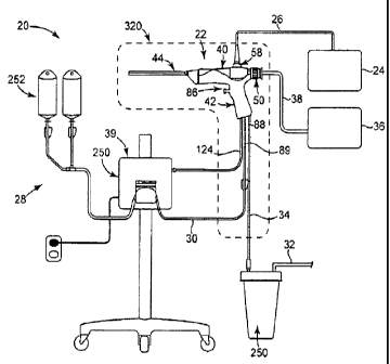
FIG. 1 shows a surgical biofilm removal system 20, according to some
embodiments. The system 20 includes a biofilm removal surgical instrument 22,
a light
source 24, a light connector 26, a fluid source 28, a fluid connector 30, a
vacuum source
32, a vacuum connector 34, an imaging device 36, an imaging connector 38, and
a
5 controller 39. In general terms, the light source 24 provides light to
the instrument 22
through the light connector 26; the fluid source 28 provides fluid to the
instrument 22
through the fluid connector 30; and the vacuum source 32 provides vacuum flow,
or
aspiratory flow, to the instrument 22 through the vacuum connector 34. The
controller 39
controls operation of the system 20 and is shown as being associated generally
with the
fluid source 28, although the controller 39 is optionally a stand-alone device
or physically
associated with any of the other system components, including, for example,
the
instrument 22.
In some embodiments, the instrument 22 includes an endoscope 40, a handle 42,
and a removable endoscope sheath 44. In general terms, the endoscope 40 is
secured
relative to the handle 42, with the handle 42 being used, in part, to
facilitate maneuvering
of the endoscope 40. The sheath 44 is secured over the endoscope 40, and in
some
embodiments, the sheath 44 is also secured to the handle 42. The sheath 44
provides a
protective barrier for the endoscope 40 and is adapted to facilitate delivery
of pressurized
fluid in substantially removing a layer of biofilm (not shown), as
subsequently described.
As shown in FIG. 2, the endoscope 40 can include various optical components
and
is generally adapted to image internal bodily structures (FIG. 10). In some
embodiments,
the endoscope 40 includes an eyepiece 50, a focus ring 52, a housing 54, a
control
assembly 56, a connection post 58, and an insertion tube 60 that defines a
working end 62
of the endoscope 40. In general terms, at least a portion of the insertion
tube 60 is
disposed inside a human body (not shown) with the working end 62 of the
endoscope 40
being disposed at a target site (FIG. 10) to be imaged. "Imaging," "adapted to
image," and
similar language should be understood to be inclusive of direct visualization
through the
optical components of the endoscope 40 as well electronic visualization and/or
data
analysis via electronic imaging, for example using the imaging device 36 (FIG.
1) or other
electronics.
CA 02674323 2009-07-02
WO 2008/085668
PCT/US2007/087696
6
In some embodiments, the eyepiece 50 is connected to the housing 54 for direct
visualization and/or electronic visualization as referenced above, with the
focus ring 52
being disposed about the eyepiece 50 and usable to bring images, or image
data, into
focus. The housing 54 maintains various optical components of the endoscope 40
and
includes a body portion 66 and a neck portion 68. The body portion 66 is
relatively
bulbous in shape. In turn, the neck portion 68 extends in a tapering manner
from the body
portion 66 and distally forms an annular connector flange 69 from within which
the
insertion tube 60 projects.
With continued reference to FIG. 2, in some embodiments, the control assembly
56
and the connection post 58 are maintained by the body portion 66. In turn, the
insertion
tube 60 is maintained by the neck portion 68 and projects from the connector
flange 69 as
referenced above. During operation, the control assembly 56 is adapted to
control
selective bending of the insertion tube 60. The connection post 58 is adapted
for
connection to the light connector 26, which, in combination with other
components of the
endoscope 40, provides light at the working end 62 of the endoscope 40.
In some embodiments, the insertion tube 60 includes optical components, such
as a
fiber-optic bundle (not shown), and is substantially elongate, defining a
proximal portion
70, which is connected to the housing 54, and a distal portion 72, which, more
specifically,
defines the working end 62 of the endoscope 40. The proximal portion 70 is
substantially
rigid while the distal portion 72 is adapted to be selectively bendable as
indicated
generally by broken lines in FIG. 2. For example, the distal portion 72 is
optionally
formed of a flexible material, a series of links, vertebrae, or is otherwise
suited to embody
bendability. The endoscope 40 includes components for actuating the distal
portion 72,
including those known to one having ordinary skill in the art, where the
control assembly
56 is operable by a user to actuate bending of the distal portion 72 to aim
the working end
62 in a desired direction.
For reference, FIG. 2 shows the distal portion 72 in several positions with
the use
of broken lines. Although, the direction of bending is shown as being within a
plane of the
drawing sheet, or within a "drawing plane," it should be understood that the
distal portion
72 additionally or alternatively is selectively bendable in a plane orthogonal
to the drawing
plane, or any number of planes for that matter. It should also be noted that,
in other
CA 02674323 2009-07-02
WO 2008/085668
PCT/US2007/087696
7
embodiments, both the proximal and distal portions 70, 72 are substantially
flexible, or
alternatively, substantially rigid. In still other embodiments, the proximal
portion 70 is
selectively bendable and/or substantially flexible, while the distal portion
72 is
substantially rigid. From this, it is readily understood that a variety of
endoscope
configurations are contemplated in association with the instrument 22 (FIG.
1).
During operation of the endoscope 40, light is optionally provided to the
working
end 62 to illuminate an internal bodily structure or other target site being
imaged, with
associated images, or image data, being transmitted back from the working end
62 through
the insertion tube 60 to the eyepiece 50 and/or associated electronic devices,
such as the
imaging device 36.
Returning to FIG. 1, the handle 42 can similarly assume a variety of forms.
One
example configuration of the handle 42 is shown in greater detail in FIGS. 3
and 4, and
includes or defines an interior 80 and optionally includes a grip portion 82,
a support
portion 84, a trigger assembly 86, first tubing 88, and a second tubing 89. As
a point of
reference, the tubings 88, 89 are removed from the view of FIG. 3 to better
illustrate other
features of the handle 42.
In some embodiments, the grip portion 82 extends from a butt end 90 and can be
characterized as being structured according to a pistol-grip configuration. In
terms of use,
the grip portion 82 is ergonomically designed to assist a user (not shown)
with grasping
and manipulating the instrument 22 (FIG. 1) during use. Alternatively, the
grip portion 82
can assume a variety of other shapes and/or sizes, and defines at least a
portion of the
interior 80 along which the trigger assembly 86 and the first and second
tubings 88, 89 are
maintained, as described below.
With specific reference to FIG. 3, the support portion 84 is connected to the
grip
portion 82, and in some embodiments is integrally formed with the grip portion
82, for
example via injection molding. Regardless, the support portion 84 forms a
scope cradle
96 adapted to releasably retain the endoscope 40 (FIG. 2), and a sheath
interface 98
adapted to releasably retain the sheath 44 (FIG. 1).
The scope cradle 96 includes or defines a proximal bracket 100, a housing
carriage
102, and a distal bracket 104. The proximal bracket 100 is substantially U-
shaped and is
configured to form a complementary fit with the endoscope 40 (FIG. 2), for
example a
CA 02674323 2009-07-02
WO 2008/085668
PCT/US2007/087696
8
frictional fit with the eyepiece 50 (FIG. 2). The proximal bracket 100 is
optionally
adapted to flex apart to some extent in order to facilitate a releasable,
friction fit with the
eyepiece 50. If desired, the proximal bracket 100 additionally or
alternatively includes a
variety of means for releasably securing the eyepiece 50 in the proximal
bracket 100,
including, for example, detents, magnets, clips, adhesives, retaining pins,
and others.
In turn, the distal bracket 104 is substantially U-shaped according to some
embodiments and includes detents 107, 108, where the distal bracket 104 is
configured to
form a complementary fit with the neck portion 68 of the endoscope 40 (FIG.
2). In this
regard, the distal bracket 104 can be adapted to flex apart to some extent in
order to
facilitate a releasable, friction fit with the neck portion 68. In particular,
the detents 107,
108 are used in some embodiments to assist in frictionally and releasably
securing the
neck portion 68 in the distal bracket 104. If desired, the distal bracket 104
additionally or
alternatively includes a variety of means for releasably securing the neck
portion 68 in the
distal bracket 104, including, for example, additional detents, magnets,
clips, adhesives,
retaining pins, and others.
The housing carriage 102 is sized and shaped to receive and support the
endoscope
40 (FIG. 2) as maintained in the proximal and distal brackets 100, 104. If
desired, the
housing carriage 102 also includes means for releasably securing the endoscope
40, such
as those mentioned in association with the proximal and distal brackets 100,
104. In some
embodiments, the housing carriage 102 defines a concave surface 106 adapted to
receive
the body portion 66 of the endoscope 40 such that there is room for the
control assembly
56, and a sloped surface 109 for receiving and/or supporting part of the neck
portion 68.
With reference between FIGS. 3 and 4, the sheath interface 98 of the grip
portion
82 forms a first receptacle 110 and a second receptacle 112 for sealingly
receiving
complementary features of the sheath 44 (FIG. 1), as will be further
elucidated in the
ensuing discussion. Additionally, the first and second receptacles 110, 112
optionally
form first and second fittings 114, 116 (FIG. 4), respectively, within the
interior 80 (FIG.
4) of the handle 42.
In some embodiments, the trigger assembly 86 includes a trigger member 120, a
trigger sensor 122, such as a switch, and a connector 124. The trigger member
120
extends external to the grip portion 82 and is adapted to be actuated by a
user (not shown),
CA 02674323 2009-07-02
WO 2008/085668
PCT/US2007/087696
9
for example via a sliding interface relative to the grip portion 82. As best
shown in FIG. 4,
the trigger member 120 can be slidably retained within a collet 125 that
further retains a
biasing device 126 (e.g., a spring) that serves to bias the trigger member 120
to the
extended position (relative to the grip portion 82) reflected in FIGS. 3 and
4. Activation
of the trigger member 120 thus entails a pushing force being applied thereon,
sufficient to
overcome a force of the biasing device 126 to thus slide the trigger member
120 inwardly
relative to the collet 125. Other actuation arrangements of the trigger member
120 are also
acceptable.
The trigger sensor 122 is adapted to provide an output indicative of actuation
(e.g.,
sliding movement) of the trigger member 120, and thus can assume a variety of
forms
appropriate for sensing movement of the trigger member 120. The connector 124,
in turn,
is adapted to carry, or transmit, the output from the trigger sensor 122.
Thus, the
connector 124 can assume a variety of forms (e.g., tubing, wire, etc.), and is
connected to
the controller 39 (FIG. 1). For example, the connector 124 is connected to the
trigger
sensor 122 and protrudes externally to the handle 42 through the butt end 90
of the grip
portion 82.
With specific reference to FIG. 4, the first tubing 88 of the handle 42 is
connected
to the first receptacle 110 via the first fitting 114. The first tubing 88
extends through the
interior 80 of the handle 42 and out of the butt end 90 of the grip portion
82. The second
tubing 89 of the handle 42 is connected to the second receptacle 112 via the
second fitting
116. The second tubing 89 also extends through the interior 80 of the handle
42 and out of
the butt end 90 of the grip portion 82. As a point of reference, a portion of
the second
tubing 89 is hidden from view behind the first tubing 88 in FIG. 4.
FIG. 5 shows the sheath 44 of the system 20 from a perspective view, according
to
some embodiments. For reference, the sheath 44, or portions thereof, is
optionally
disposable. Alternatively, the sheath 44 can be reusable and adapted for
sterilization or
otherwise adapted to be cleaned. In some embodiments, the sheath 44 includes a
manifold
128, a barrier portion 130, an aspiration duct 132 (referenced generally), and
an irrigation
duct 134 (referenced generally). In general terms, the manifold 128 is adapted
to be
releasably connected to the endoscope 40 (FIG. 2) and the handle 42 (FIG. 3).
In turn, the
barrier portion 130 is adapted for insertion into a patient's anatomy.
CA 02674323 2009-07-02
WO 2008/085668
PCT/US2007/087696
The barrier portion 130 includes an outer sleeve 135, and, in some
embodiments, is
assembled to define a distalsegment 136. The distal segment 136 is described
below as
being bendable in association with some embodiments; it will be understood,
however,
that a remainder of the barrier portion 130 can be substantially flexible,
rigid, malleable, or
5 combinations thereof as desired. Alternatively, the distal segment 136
can be substantially
rigid and not bendable.
With additional reference to FIG. 6 (that otherwise illustrates portions of
the outer
sleeve 135 with broken lines), in some embodiments, the manifold 128 includes
or forms a
primary frame 137, a sleeve hub 138 and an insertion tube guide 140. The
manifold 128
10 also defines an interior 142 (FIG. 9) and forms a scope connector 144
and a handle
interface 146. The scope connector 144 is adapted to be releasably secured to
the
connector flange 69 (FIG. 2) of the endoscope 40 (FIG. 2).
In some embodiments, the sleeve hub 138 projects distally from the frame 137
and
is adapted to form a complementary fit with the barrier portion 130. The
insertion tube
guide 140 is an annular, hollow body, projecting distally from the sleeve hub
138. The
insertion tube guide 140 is adapted to slidably receive the insertion tube 60
(FIG. 2) of the
endoscope 40 (FIG. 2) according to some embodiments.
The scope connector 144 extends from the frame 137 opposite the sleeve hub
138,
and includes a plurality of projections or fingers 148. In addition, the scope
connector 144
can include a first release member 150 and a substantially similar second
release member
(hidden in the view of FIG. 6) opposite the first release member 150, in some
embodiments. In particular, one or more of the plurality of projections 148
are adapted to
be deflected upon insertion within the connector flange 69 (FIG. 2) of the
endoscope 40
(FIG. 2) to releasably mate therewith. The first release member 150 and the
second
release member are associated with one or more of the plurality of projections
148 such
that depression of the respective release member(s) 150 causes one or more of
the plurality
of projections 148 to deflect inwardly to release the scope connector 144 from
the
connector flange 69. In this manner, the scope connector 144 acts according to
what can
be described as a "spring clip and release" or a "quick connect and release"
mechanism in
combination with the handle interface 146.
CA 02674323 2009-07-02
WO 2008/085668
PCT/US2007/087696
11
In some embodiments, the handle interface 146 forms a first coupling head 154
and second coupling head 156, which are adapted to be insertable within, as
well as form
complementary fits with, the first and second receptacles 110, 112 (FIG. 4),
respectively,
of the handle 42 (FIG. 4). Each of the first and second coupling heads 154,
156 optionally
includes a plurality of other sealing means 160, such as o-rings, for forming
a vacuum-
tight and/or a liquid-tight seal, for example, with the first and second
receptacles 110, 112,
respectively.
In some embodiments, the outer sleeve 135 includes a substantially cylindrical
sleeve body 178 defining a proximal end 174, a distal end 176, and a central
lumen or
similar open space 180. The outer sleeve 135 also includes a viewing window
182. For
reference the distal end 176 is sealed to the viewing window 182, as well as
the aspiration
and irrigation ducts 132, 134 such that the central lumen 180 is closed off,
or sealed, from
environment at the distal end 176. However, it is contemplated that in other
embodiments,
the distal end 176 is not sealed or is open, providing a path into the central
lumen 180. As
referenced above, in FIGS. 6-8, a border of the sleeve body 178 is shown with
broken
lines to better allow understanding of features residing within the sleeve
body 178.
The sleeve body 178 is optionally formed of a substantially flexible, and, in
some
embodiments, elastomeric material. Although the figures reflect the sleeve
body 178 as
being substantially circular in transverse cross-section, it should be
understood that, in
some embodiments, the sleeve body 178 optionally conforms to the aspiration
duct 132
and/or irrigation duct 134 to a greater extent than shown. Additionally or
alternatively, the
sleeve body 178 is substantially rigid or substantially malleable in other
embodiments.
In order to give a point of reference as to the variety of sheath
configurations
contemplated, it should be noted that in some embodiments, substantially all
the sleeve
body 178 of the outer sleeve 135 is flexible, or bendable; in other
embodiments, the sleeve
body 178 is flexible proximate the distal end 176 and more rigid proximate the
proximal
end 174, or vice versa; and in still other embodiments, substantially all of
the sleeve body
178 is substantially rigid.
As best shown in FIG. 7, the viewing window 182 includes a housing 184 and a
lens 186 secured to the housing 184, where the housing 184 is hollow and
adapted to
receive the working end 62 (FIG. 2) of the endoscope 40 (FIG. 2) such that the
working
CA 02674323 2009-07-02
WO 2008/085668
PCT/US2007/087696
12
end 62 abuts or comes in close proximity to the lens 186 upon final assembly.
The
viewing window 182 is secured within the central lumen 180 at or adjacent the
distal end
176 of the sleeve body 178. For example, the viewing window 182 is optionally
adhesively secured at the distal end 176. For reference, and as alluded to
above, the distal
end 176 of the sleeve body 178 is optionally sealed to the lens 186 to help
prevent
environment at the distal end 176 from entering the central lumen 180.
With reference to FIGS. 6, 8, and 9, the aspiration duct 132 is formed of, or
defined by, a plurality of sections 190, including a manifold section 190A, a
proximal
sleeve section 190B (largely obscured by the irrigation duct 134 in FIG. 6),
and a distal
sleeve section 190C. The aspiration duct 132 can be supported by a
reinforcement
assembly 192 (FIG. 8), and defines a proximal end 194 (FIG. 9), a distal inlet
end 196
(FIG. 8), a distal inlet 197 (FIG. 8), and a lumen 198 (FIG. 8) for conveying
an aspiratory
flow between the proximal and distal ends 194, 196. For reference, the
plurality of tubular
sections 190 is formed as a single, continuous component; as separate,
connected
components; or combinations thereof, according to various embodiments. The
aspiration
duct 132, is optionally substantially flexible, substantially rigid,
substantially malleable, or
combinations thereof
As best shown in FIG. 9 (that otherwise illustrates the instrument 22 upon
final
assembly), the manifold section 190A is optionally substantially rigid and/or
formed as a
part of the manifold 128, for example being injection molded as a single piece
with the
manifold 128. In other embodiments, the manifold section 190A is formed of a
separate,
substantially elongate, flexible, tube (or "cannula"). Regardless, the
manifold section
190A of the aspiration duct 132 is in fluid communication with the first
coupling head 154
of the manifold 128 and defines a portion of the lumen 198 (FIG. 8) of the
aspiration duct
132.
With specific reference to FIGS. 6 and 8, in some embodiments, the proximal
sleeve section 190B (largely hidden) of the aspiration duct 132 is
substantially rigid and/or
is formed continuously with the manifold section 190A (FIG. 9), for example
being
injection molded as a single piece with the manifold section 190A. In other
embodiments,
the proximal sleeve section 190B is formed of a separate, substantially
elongate, flexible,
tube (or "cannula"), in fluid communication with the manifold section 190A.
Regardless,
CA 02674323 2009-07-02
WO 2008/085668
PCT/US2007/087696
13
the proximal sleeve section 190B extends distally from, and is in fluid
communication
with, the manifold section 190A and defines a portion of the lumen 198.
As best shown in FIG. 8, in some embodiments, the distal sleeve section 190C
is
substantially flexible and/or is formed as a separate, substantially elongate,
tube (or
"cannula"), in fluid communication with the proximal sleeve section 190B. As
will be
described in greater detail below, flexibility of the distal sleeve section
190C allows
selective bending of the distal portion 72 (FIG. 2) of the endoscope 40 (FIG.
2) according
to some embodiments. In other embodiments, the distal sleeve section 190C is
substantially rigid and/or is formed continuously with the proximal sleeve
section 190B as
a single piece. Regardless, the distal sleeve section 196C of the aspiration
duct 132
extends distally from, and is in fluid communication with, the proximal sleeve
section
190B and defines a portion of the lumen 198.
As mentioned above, the aspiration duct 132, and in particular the distal
sleeve
section 196C thereof, can be supported by the reinforcement assembly 192. With
this in
mind, the reinforcement assembly 192 can include a reinforcement member 200
and an
end piece 202. The reinforcement assembly 192 is maintained within the distal
sleeve
section 190C, proximal the distal inlet end 196.
The reinforcement member 200 is optionally a spring-like member which is
bendable, yet resistant to being radially collapsed. Thus, the reinforcement
member 200
provides the distal sleeve section 190C with some resistance to collapsing,
while still
being bendable, for example, where the distal sleeve section 190C is otherwise
formed of
a substantially flexible member that might collapse under the negative
pressure of an
aspiratory flow. It should also be noted that in other embodiments, the
reinforcement
member 200 is disposed around the distal sleeve section 190C, or even as an
integral
component of the distal sleeve section 190C.
The end piece 202 is tubular and is optionally substantially rigid, assisting
with
reinforcement of the distal sleeve section 190C according to some embodiments.
For
reference, the end piece 202 and/or the distal inlet end 196 of the aspiration
duct 132 is
optionally sealed to the distal end 176 of the outer sleeve 135 to help
prevent
contamination of the central lumen 180 of the outer sleeve 135.
CA 02674323 2009-07-02
WO 2008/085668
PCT/US2007/087696
14
The irrigation duct 134 is similar to the aspiration duct 132, and includes
(with
combined reference to FIGS. 6, 8, and 9) a plurality of sections 210,
including a manifold
section 210A, a proximal sleeve section 210B, and a distal sleeve section
210C. The
irrigation duct 134 is fluidly connected to a nozzle 212, and defines a
proximal end 214
(FIG. 9), a distal outlet end 216, a distal outlet 217 (FIG. 7), and central
lumen 218 for
conveying a fluid (not shown) between the proximal and distal ends 214, 216
and out the
distal outlet 217. For reference, the plurality of sections 210 is formed as a
single,
continuous component; as separate, connected components; or combinations
thereof,
according to various embodiments. The irrigation duct 134, is optionally
substantially
flexible, substantially rigid, substantially malleable, or combinations
thereof Although, it
should be noted that the distal sleeve section 210C is bendable in some
embodiments to
accommodate flexibility of the bendable section 136 (FIG. 5) of the barrier
portion 130
(FIG. 5).
With reference to FIG. 9, the manifold section 210A is optionally
substantially
rigid and/or formed as a part of the manifold 128, for example being injection
molded as a
single piece with the manifold 128. In other embodiments, the manifold section
210A is
formed of a separate, substantially elongate, flexible, hollow, tube, which
can also be
described as a "cannula." Regardless, the manifold section 210A of the
irrigation duct 134
is in fluid communication with the second coupling head 156 of the manifold
128 and
defines a portion of the lumen 218 (FIG. 8) of the irrigation duct 134.
With reference between FIGS. 6 and 9, in some embodiments, the proximal sleeve
section 210B is substantially rigid and/or is formed continuously with the
manifold section
210A, for example being injection molded as a single piece with the manifold
section
210A. In other embodiments, the proximal sleeve section 210B is formed of a
separate,
substantially elongate, flexible, tube (or "cannula"), in fluid communication
with the
manifold section 210A. Regardless, the proximal sleeve section 210B of the
irrigation
duct 134 extends distally from, and is in fluid communication with, the
manifold section
210A and defines a portion of the lumen 218 (FIG. 8) of the irrigation duct
134.
In some embodiments, the distal sleeve section 210C is substantially flexible
and/or is formed as a separate, substantially elongate, tube (or "cannula"),
in fluid
communication with the proximal sleeve section 210B. As will be described in
greater
CA 02674323 2009-07-02
WO 2008/085668
PCT/US2007/087696
detail below, flexibility of the distal sleeve section 210C allows selective
bending of the
bendable section 136 of the endoscope 40 according to some embodiments. In
other
embodiments, the distal sleeve section 210C is substantially rigid and/or is
formed
continuously with the proximal sleeve section 210B as a single piece.
Regardless, the
5 distal sleeve section 210C of the irrigation duct 134 extends distally
from, and is in fluid
communication with, the proximal sleeve section 210B and defines a portion of
the lumen
218 (FIG. 8) of the irrigation duct 134.
With reference to FIG. 8, the nozzle 212 is a hollow, tube (or "cannula")
adapted
to act as a flow restricter in some embodiments. The nozzle 212 defines the
distal outlet
10 217 in some embodiments, causing fluid to be ejected from the irrigation
duct 134
according to a desired flow rate and/or flow pattern, such as, a jet, spray,
stream, aerosol,
or other flow pattern. The nozzle 212 is maintained within the central lumen
218 at the
distal sleeve section 210C, at or adjacent the distal outlet end 216 of the
irrigation duct
134. In some embodiments, the nozzle 212 and/or the distal outlet end 216 of
the
15 irrigation duct 134 is sealed to the distal end 176 of the outer sleeve
135 to help prevent
environmental contamination of the central lumen 180 of the outer sleeve 135
while still
allowing a flow of fluid through the nozzle 212 and out of the distal outlet
217.
With reference to FIG. 6, the sheath 44 is assembled according to some
embodiments by disposing the proximal and distal sleeve sections 190B, 190C,
210B,
210C, of the aspiration duct 132 and the irrigation duct 134, respectively,
within the
central lumen 180 of the outer sleeve 135. In turn, the proximal end 174 of
the outer
sleeve 135 is secured, releasably or otherwise, over the sleeve hub 138 of the
manifold
128. The distal ends 196, 216 of the aspiration and irrigation ducts 132, 134,
respectively,
are sealed to the distal end 176 of the outer sleeve 135 in some embodiments
to help close
the lumen 180 of the outer sleeve 135 from environment at the distal end 176
thereof
However, it should be understood that the aspiration and irrigation ducts 132,
134
themselves, and in particular the central lumens 198, 218 (FIG. 8),
respectively, at the
distal inlet end 196 and distal outlet end 216 are exposed, or open, through
the distal end
176 of the outer sleeve 135 such that irrigant can pass out of the irrigation
duct 134 and
inspiratory flow and associated, aspirated matter can pass into the aspiration
duct 132
proximate the distal end 176 of the outer sleeve 135.
CA 02674323 2009-07-02
WO 2008/085668
PCT/US2007/087696
16
With reference to FIG. 7, in some embodiments, the distal outlet end 216 of
the
irrigation duct 134 is secured relative to the distal end 176 of the outer
sleeve 135 such
that the nozzle 212 (referenced generally) points longitudinally in
substantially the same
direction as the viewing window 182. In this manner, the working end 62 (FIG.
2)
endoscope 40 (FIG. 2) can be used to observe an area or target that a flow of
irrigant from
the nozzle 212 is striking when the irrigant is within a field of view of the
endoscope 40.
In other embodiments, the nozzle 212 and the viewing window 182 are oriented
to define
an intersection point (i.e., where the longitudinal line-of-sight from the
viewing window
182 intersects the longitudinal line of flow from the nozzle 212) distal to
the viewing
window 182, to promote viewing of the flow of irrigant proximate the
intersection point.
The distal inlet end 196 of the aspiration duct 132 is also secured relative
to the outer
sleeve 135 and/or irrigation duct 134, according to some embodiments, such
that the distal
inlet end 196 points in a substantially similar direction as the nozzle 212
and/or viewing
window 182, although other orientations are also contemplated.
In view of the above, it should be understood that in some embodiments, at
least
one of the aspiration and irrigation ducts 132, 134 is associated with the
sheath 44. As
used herein, "associated with the sheath" is indicative of at least one of the
ducts 132, 134,
respectively, being included as a part of the sheath 44, such as being
disposed or formed
within the outer sleeve 135, on the outer sleeve 135, or being secured
relative to the outer
sleeve 135. Furthermore, it should be understood that in some embodiments, the
distal
sleeve sections 190C, 210C of the aspiration and irrigation ducts 132, 134, as
well as at
least a corresponding portion of the outer sleeve 135, respectively, form the
bendable
section 136 of the barrier portion 130 such that it is repeatably bendable in
conjunction
with selective bending of the endoscope 40, as previously alluded to, and as
subsequently
described.
Assembly of the surgical instrument 22 according to some embodiments is
described below with reference to FIG. 9. The endoscope 40 is secured to the
handle 42
by releasably receiving the eyepiece 50 of the endoscope 40 in the proximal
bracket 100
(FIG. 4) of the handle 42. The neck portion 68, and in particular, the
connector flange 69,
of the endoscope 40, in turn, is releasably received in the distal bracket 104
(FIG. 4) of the
handle 42. With the endoscope 40 so-received, the body portion 66 rests over
the concave
CA 02674323 2014-04-10
53591-6
17
surface 106, while allowing room for actuation of the control assembly 56,
with the neck
portion 68, in turn, resting over and/or against the sloped area 109 of the
housing carriage
102.
In some embodiments, the endoscope 40 is assembled to the sheath 44 as
follows.
The insertion tube 60 of the endoscope 40 is slid through the scope connector
144 and the
insertion tube guide 140 of the manifold 128, and into the central lumen 180
of the outer
sleeve 135, such that the working end 62 (referenced generally) is received
against the lens
186 (FIG. 7). With the working end 62 so-received, the working end 62 is
secured relative
to the sheath 44, and in particular relative to the irrigation duct 134, the
aspiration duct
132, and the nozzle 212 (FIG. 8).
The endoscope 40 is releasably secured to the handle 42 by inserting the scope
connector 144 of the handle 42 into the connector flange 69 of the endoscope
40 to
releasably secure the two, as previously referenced. From the foregoing, it
should be
understood that features and methods for assembling the instrument 22 as
provided above
are not only releasable, but also quick and intuitive in nature according to
some
embodiments.
Returning to FIG. 1, other components of the system 20 can assume a variety of
forms. For example, the light source 24 can be adapted to provide illumination
to the
endoscope 40, is secured to the connection post 58 of the endoscope 40 via the
light
connector 26, and can be of a type known to those of skill in the art. As
previously
referenced, the light source 24 provides light to the instrument 22, for
illuminating a target
site (FIG. 10).
The fluid source 28 includes a pump 250 connected to a reservoir 252. In some
embodiments, the pump 250 is a peristaltic pump, such as those typically used
in
association with surgical and/or endoscopic procedures, the pump 250 serving
to
pressurize a flow of fluid from the reservoir 252 to the instrument 22 as
described below.
The reservoir 252 includes one or more IV bags, for example, filled with an
irrigant,
including the irrigating fluids described in U.S. Pat. Publication No.
2007/0264296 Al,
entitled, "Biofilm Extracellular Polysaccharide Solvating (EPS) System," and
filed on
May 10, 2006. In some embodiments, the irrigant includes medicaments,
including those
adapted to interfere with bacterial
CA 02674323 2009-07-02
WO 2008/085668
PCT/US2007/087696
18
biofilm re-growth, surfactants, gels, antimicrobials, steroids, growth
hormones, chemicals
for reducing biofilm adhesion force, and others.
The fluid source 28 is fluidly connected to the instrument 22 via the fluid
connector 30, which is a tubing set, for example. In particular, the fluid
connector 30 is in
fluid communication with (or is formed as part of) the second tubing 89 of the
handle 42.
The second tubing 89, in turn, is in fluid communication with the irrigation
duct 134 (FIG.
9) of the sheath 44 upon assembly of the instrument 22. This places the
irrigation duct
134 in fluid communication with the fluid source 28. It should also be noted
that, in some
embodiments, the fluid connector 30 can include an auxiliary inlet or port
(not shown), for
introducing medicaments into irrigant (not shown) flowing from the fluid
source 28 and to
irrigation duct 134, for example, medicaments such as those previously
referenced.
The vacuum source 32 (referenced generally) is adapted to provide an
aspiratory,
or vacuum flow, to the instrument 22 via the vacuum connector 34. The vacuum
source
32 is optionally of a type commonly used in association with surgical and/or
endoscopic
procedures and can include a collection canister 250 fluidly connecting a
source of
negative pressure (not shown) to the vacuum connector 34. The vacuum connector
34 is
placed into fluid communication with, or is formed as part of, the first
tubing 88 of the
handle 42 and the source of negative pressure 32. The first tubing 88, in
turn, is in fluid
communication with the aspiration duct 132 (FIG. 9) of the sheath 44 upon
assembly of
the instrument 22. In this manner, the aspiration duct 132 is in fluid
communication with
the vacuum source 32 according to some embodiments, such that an aspiratory
flow is
"pulled" through the aspiration duct 132 with the vacuum source 32.
Additionally, in
some embodiments, the canister 250 serves as a disposal means, such as a
disposal tank,
for collecting debris and other matter aspirated using the instrument 22,
including those
generally used in surgical and/or endoscopic procedures.
The imaging device 36 is optionally an image sensor, such as a video camera,
display, and/or other imaging electronics, including those typically used in
association
with endoscopic procedures. The imaging device 36 is connected to the
instrument 22 via
the imaging connector 38. In particular, the imaging connector 38 is placed
into optical
communication with the eyepiece 50 of the endoscope 40. As is conventionally
known,
CA 02674323 2009-07-02
WO 2008/085668
PCT/US2007/087696
19
the imaging device 36 and the endoscope 40 are used for imaging before,
during, and/or
after a surgical procedure using the instrument 22.
As previously referenced, the controller 39 controls operation of the system
20 and
is designated as being physically associated with the fluid source 28,
although the
controller 39 is optionally a stand-alone device or physically associated with
any of the
other system components, including, for example, the handle 42 or sheath 44 of
the
instrument 22. In some embodiments the controller 39 includes a microchip,
memory,
and/or other appropriate control electronics.
The controller 39 is placed in communication with the instrument 22 and the
fluid
source 28. For example, the controller 39 is electrically connected to the
instrument 22 via
the connector 124 of the trigger assembly 86 (referenced generally). The
controller 39 can
also be placed in direct or indirect communication with the fluid source 28
and/or vacuum
source 32 via wiring or alternate means as appropriate, for example using
wireless
transmitters and receivers. Regardless, in some embodiments, actuation of the
trigger
assembly 86 sends a signal to the controller 39, which in turn activates the
fluid source 28
to provide a flow of irrigant to the instrument 22 as desired. In some
embodiments, the
controller 39 can further control operation of the vacuum source 32, either
directly or
indirectly. It should also be noted that the controller 39 can be programmed
to operate the
system 20 according to a variety of desired irrigation and/or aspiration
profiles, including
ramped actuation, time delays, varied flow patterns, and others.
The surgical biofilm removal system 20 can be employed to perform a variety of
procedures at various anatomical locations of a patient. By way of but one
example, FIG.
10 illustrates internal bodily structures 300 of a patient, including sinus
cavities such as
maxillary sinuses 310A, 310B and frontal sinuses 312A, 312B, which are
accessed
through nares 314A, 314B. It should be noted that external features of the
patient,
including the nares 314A, 314B, are shown in dotted lines. For some procedures
with
which the system 20 is useful (e.g., a patient suffering from chronic
rhinosinusitis), a first
target site 316 can be designated in association with a surface of the
maxillary sinus 310A
for description of a surgical methodology for substantially removing a layer
of biofilm. It
should be understood, however, that similar principles apply across
embodiments,
including a variety of target sites associated with a variety of internal
bodily structures,
CA 02674323 2009-07-02
WO 2008/085668
PCT/US2007/087696
such as sinus cavities (the maxillary, frontal, sphenoid, and others),
cavities of the ear (the
middle ear, and others), etc. With that in mind, in some embodiments, the
first target site
316 is ciliated epithelium of the maxillary sinus 310A that has an associated
layer of
bacteria and associated biofilm (not shown). In other embodiments, the target
site 316 is
5 an artificial structure (not shown), such as sinus packing or a stent
covered with a layer of
bacterial biofilm, for example.
With combined reference to FIG. 1 and FIG. 10, and with the foregoing
description
of the system 20 in mind, some methods of removing bacterial biofilm (not
shown) from
one or more target sites internal to a patient include the following: setting
up the system
10 20; inserting a distal portion of the instrument 22 into the maxillary
sinus 310A; aiming
the distal portion of the instrument 22 (in particular the nozzle 212 (FIG.
8)) at the target
site 316; delivering a pressurized flow of irrigant (not shown) from the
irrigation duct 134
(FIG. 8) and the nozzle 212 to the target site 316 to remove a substantial
amount of the
bacterial biofilm; and aspirating the irrigant, removed biofilm, and/or bodily
secretions
15 (not shown) away from the target site 316 through the distal inlet 197
(FIG. 7) of the
aspiration duct 132 (FIG. 8).
In some embodiments, a functional endoscopic sinus surgery (FESS) is also
performed prior to, or concurrently with, insertion of the instrument 22. For
example, the
endoscope 40, and more generally, the instrument 22, is optionally adapted
for, and/or
20 used in combination with other implements as desired for, gaining access
to the target site
316 as part of an FESS procedure.
Setting up the system 20 according to some embodiments includes releasably
securing the endoscope 40, the handle 42, and the sheath 44 together as
previously
described, where friction fit, detent, and/or "spring clip and release"
mechanisms
according to some embodiments provide a releasable assembly, that is quick and
intuitive
in nature. Other system components, including the light source 24, fluid
source 28,
vacuum source 32, imaging device 36, and controller 39 are connected to the
instrument
22 as appropriate. Additionally, a sterile barrier 320 (illustrated
schematically in FIG. 1),
such as sheeting or others commonly used in surgical and/or endoscopic
procedures, is set
up around the instrument 22 and the patient in some embodiments to help
maintain a
sterile operating environment.
CA 02674323 2009-07-02
WO 2008/085668
PCT/US2007/087696
21
As referenced above, although some embodiments of acting upon a target site to
remove a layer of biofilm are described with reference to the maxillary sinus
310A and the
target site 316, it should be understood that biofilm removal at with other
target sites
and/or other cavities, including sinus cavities or cavities of the middle ear
(not shown),
proceeds in a substantially similar manner. With this in mind, inserting the
distal portion
of the instrument 22 into the maxillary sinus 310A includes a practitioner
(not shown)
grasping the handle 42 and inserting the working end 62 (FIG. 2) of the
endoscope 40
(FIG. 2) (as positioned within the sheath 44 as previously described) into the
nares 314A
and toward the maxillary sinus 310A. In some embodiments, the endoscope 40
acquires
images during insertion in order to assist a surgeon or other practitioner
guiding the
instrument 22.
With additional reference to FIG. 2, the distal portion 72 of the endoscope
insertion
tube 60 is then selectively bent using the control assembly 56 to aim the
working end 62 of
the endoscope 40 in a desired direction and/or to facilitate insertion of the
instrument 22
into the maxillary sinus 310A. The distal, bendable section 136 of the sheath
44 is also
bent in conjunction with the selective bending of the distal portion 72. In
particular, the
distal end 176 of the outer sleeve 135, including the viewing window 182 (FIG.
5), is
moved with movement of the working end 62 of the endoscope 40. Additionally,
the
distal ends 196, 216 (FIG. 8) of the aspiration and irrigation ducts 132, 134
(FIG. 8)
respectively, as well as the nozzle 212 (FIG. 8) are also aimed, or otherwise
track along
with the working end 62 of the endoscope 40.
In some embodiments, the user (not shown) determines that the instrument 22 is
properly "aimed" or otherwise disposed as desired in the maxillary sinus 310A
relative to
a target site for debriding. For example, the user optionally determines
proper positioning
using images acquired with the endoscope 40 and displayed to the user with the
imaging
device 36. In some embodiments, the user identifies target site 316 by
observing the
presence/location of the layer of biofilm, for example by evaluating images
displayed to
the user with the imaging device 36.
The user (not shown) then prompts delivery of a pressurized flow of irrigant
to the
target site 316 to effectuate removal or eradication of a substantial amount
of the bacterial
biofilm (not shown) from the target site 316 by squeezing the trigger member
120 (FIG.
CA 02674323 2009-07-02
WO 2008/085668
PCT/US2007/087696
22
3). In response to this actuation, a signal is sent to the controller 39 that
in turn prompts
activation of the fluid source 28 to provide a flow of irrigant through the
irrigation duct
134 (FIG. 8) and the nozzle 212 (FIG. 8). It is contemplated that the flow of
irrigant will
be directed through the nozzle 212 at a variety of flow rates according to
various
embodiments, including a flow rate from about 2 ml/s to about 12 ml/s. In some
embodiments, the system 20 is adapted to cause pulsed flow through the nozzle
212, in
others substantially continuous flow, and in still others, a flow pattern
other than pulsed or
substantially continuous flow.
In some embodiments, the flow of irrigant dispensed from the nozzle 212
directly
impinges upon, or otherwise directly strikes, the target site 316 to
mechanically agitate and
remove a substantial portion, or substantially all, of the biofilm (not
shown). In other
words, the nozzle 212 is able to be pointed directly at the target site 316 as
previously
described when sufficiently accessible with the instrument 22, such that a
mechanical
"scrubbing" action is accomplished. It should be noted that the pressure
and/or flow rate
of the irrigant is selected to promote mechanical removal of the biofilm
without substantial
damage to underlying tissue, such as a ciliated epithelium layer. For example,
in some
embodiments, a pressure of less than about 50 psi at the target site 316 is
selected,
although other pressures are contemplated.
In some embodiments, aspiration of bacterial biofilm, bacteria, mucous,
secretions,
dead tissue, or other unwanted matter is accomplished using the aspiration
duct 132 (FIG.
8), for example during and/or after dispensing the irrigant (not shown)
against the target
site 316. The instrument 22 is operated to selectively or continuously
activate the vacuum
source 32 in response to the user pulling the trigger member 120 (FIG. 3), for
example
concurrently with irrigation or with some time differential (for example,
before or after
irrigation). The unwanted matter is removed from proximate the target site 316
and is
optionally directed to the biological collection canister 250 associated with
the vacuum
source 32.
The systems and methods described above are highly useful in surgically
treating
various maladies associated with multiple different anatomical locations or
target sites.
For example, in addition to sinus and inner ear target sites, the systems and
methods of the
present disclosure can be used to treat target site(s) in patient's lungs
(e.g., cystic fibrosis
CA 02674323 2009-07-02
WO 2008/085668
PCT/US2007/087696
23
in the respiratory epithelium of the lungs), urological and/or gynecological
(e.g., urinary
tract infections), etc.
In view of the above, a method for removing biofilm from a surface within an
internal bodily cavity (or other target site) under endoscopic visualization
is provided
according to some embodiments. It should be noted that various functions of
the
instrument 22 are optionally provided according to alternative embodiments,
such as those
described below in association with FIGS. 11-14.
FIG. 11 shows a duct assembly 400 optionally forming a part of the system 20
(FIG. 1) according to some other embodiments. In some embodiments, the duct
assembly
400 is not otherwise associated with the sheath 44 (FIG. 5) and is usable as a
separate,
distinct component. With this in mind, the duct assembly 400 includes an inner
tube (or
"inner cannula") 410 and an outer tube (or "outer cannula") 412.
The inner tube 410 is elongate and hollow, and defines a proximal end 420, a
distal
end 422, and a distal portion 424 proximate the distal end 422. A connector
428, such as a
luer connector, is assembled to at the proximal end 420. In some embodiments,
the distal
portion 424 defines a natural bend and is substantially flexible, such that
the distal portion
424 is bendable into a substantially straight or less bent configuration upon
exertion of an
outside force, but will recover the natural bend upon removal of the external
force (it
being understood that in the view of FIG. 11, the distal portion 424 is
deflected to, or held
in, a straightened state).
The outer tube 412 is elongate and hollow, and defines a proximal end 430, a
distal
end 432, and a distal portion 434 proximate the distal end 432. In some
embodiments, the
distal portion 434 defines a bend and is substantially less flexible, or
relatively rigid, in
comparison to the distal portion 424 of the inner tube 410.
FIG. 12 shows the duct assembly 400 of FIG. 11 in a deployed state, versus a
retracted state as shown in FIG. 11. In particular, the inner tube 410 is
coaxially and
slidably received in the outer tube 412 such that the distal end 422 of the
inner tube 410
can initially be housed within the outer tube 412 in the retracted state and
be slid out of the
distal end 432 of the outer tube 412 to define the deployed state. In some
embodiments,
the natural bend of the distal portion 424, in combination with the bend of
the distal
portion 434, causes the distal end 422 of the inner tube 410 to travel through
an arcuate
CA 02674323 2009-07-02
WO 2008/085668
PCT/US2007/087696
24
path as the distal end 422 is deployed from the outer tube 412. In operation,
this allows
the distal end 422 to be deployed to a target site in relatively tight areas,
such as the sinus
cavities. In particular, the duct assembly 400 defines a relatively elongate
and compact
retracted state, but can be used to curve around into hard to reach areas in
the deployed
state.
In terms of use, the duct assembly 400 is optionally used to functionally
and/or
physically replace use of the aspiration duct 132 (FIG. 8), wherein the duct
assembly 400
is connected to the vacuum source 32 (FIG. 1) using the connector 428 to
aspirate
proximate the target site 316, for example. It should also be noted that a
reinforcement
member, such as one similar to the reinforcement member 192 (FIG. 8), is
optionally used
in association with the duct assembly 400, for example proximate the distal
end 422 of the
inner tube 410. Additionally, if desired, the duct assembly 400 can similarly
serve instead
as an irrigation duct, with a nozzle similar to the nozzle 212 (FIG. 8), for
example, secured
proximate the distal end 422 of the inner tube 410. Thus, where the duct
assembly 400 is
used, methods of biofilm removal include disposing an inlet end of an
aspiration duct non-
concurrently with disposing a nozzle of an irrigation duct proximate a target
site,
according to some embodiments where an irrigation duct and aspiration duct of
the system
are not physically associated with one another, for example where the duct
assembly
400 is used to replace (physically or functionally) features of the sheath 44
(FIG. 1),
20 according to some embodiments.
FIG. 13 shows an alternative duct assembly 500 optionally forming a part of
the
system 20 (FIG. 1). In some embodiments, the duct assembly 500 is not
otherwise
associated with the sheath 44 (FIG. 1) and is usable as a separate, distinct
component. The
duct assembly 500 includes an inner tube (or "inner cannula") 510 and an outer
tube (or
"outer cannula") 512.
The inner tube 510 is elongate and hollow and defines a proximal end 520, a
distal
end 522, a distal portion 524 proximate the distal end 522, a proximal portion
526 more
proximate the proximal end 520 and an intermediate portion 528 between the
distal and
proximal portions 524, 526. A connector 530, such as a luer connector, is
mounted to the
inner tube 510 at the proximal end 520. In some embodiments, each of the
distal and
proximal portions 524, 526 are substantially inflexible, while the
intermediate portion 528
CA 02674323 2009-07-02
WO 2008/085668
PCT/US2007/087696
defines a natural bend and is substantially flexible, such that the distal
portion 524 is
collapsible toward the proximal portion 526 into a more bent configuration
upon exertion
of an outside force, but will recover the natural bend upon removing the
external force.
The outer tube 512 is elongate and hollow, and defines a proximal end 530, a
distal
5 end 532, and a retainer 534 proximate the distal end 532. In some
embodiments, the
retainer 534 is sized and shaped to receive the distal portion 524 of the
inner tube 510.
FIG. 14 shows the duct assembly 500 of FIG. 13 in a deployed state versus a
collapsed state as shown in FIG. 13. In particular, the duct assembly 500
defines a
collapsed state where the inner tube 510 is coaxially and slidably received in
the outer
10 tube 512 such that the distal end 522 of the inner tube 510 is bent back
toward the
proximal portion 526, with the distal end 522 received in the retainer 534.
The inner tube
510 is then slid distally in the outer tube 512 to release the distal end 522
from the retainer
534, such that the intermediate portion 528 transitions back to the natural
bend and the
duct assembly 500 defines the deployed state. In operation, inserting the duct
assembly
15 500 in the collapsed state allows the duct assembly 500 to be deployed
to a target site in
relatively tight areas, such as the sinus cavities. In particular, the duct
assembly 500
defines a relatively compact collapsed state, but can be used to hook or curve
around into
hard to reach areas, such as sinus cavities, in the deployed state.
In terms of use, the duct assembly 500 is optionally used to functionally
and/or
20 physically replace use of the aspiration duct 132 (FIG. 8), wherein the
duct assembly 500
is connected to the vacuum source 32 (FIG. 1) using the connector 530 to
aspirate
proximate the target site 316 (FIG. 10), for example. It should also be noted
that a
reinforcement member, such as one similar to the reinforcement member 192
(FIG. 8), is
optionally used in association with the duct assembly 500, for example
proximate the
25 distal end 522 of the inner tube 510. Additionally, if desired, the duct
assembly 500 can
similarly serve instead as an irrigation duct, with a nozzle similar to the
nozzle 212 (FIG.
8), for example, secured proximate the distal end 522 of the inner tube 510.
Thus, where
the duct assembly 500 is used, methods of biofilm removal include disposing an
inlet end
of an aspiration duct non-concurrently with disposing a nozzle of an
irrigation duct
proximate a target site, where the irrigation duct and aspiration duct are not
physically
associated with one another. In other words, where the duct assembly 500 is
used for
CA 02674323 2014-04-10
53591-6
26
aspiration or irrigation and is separate from the sheath 44 (FIG. 1), for
example, the duct
assembly 500 is disposed at the target site 316 at a different time than the
sheath 44,
according to some embodiments.
The systems and methods of the present disclosure provide a marked improvement
over previous techniques and devices used to treat various ailments, such as
chronic
rhinosinusitis. By effectuating biofilm eradication using a focused,
pressurized fluid, a
more complete treatment is provided to the patient on a minimally invasive
basis. Further,
with sinus and other applications, drainage pathway(s) are restored,
ventilation of the
treatment site is provided (thus minimizing opportunities for biofilm re-
growth), and other
functional endoscopic sinus surgery treatments can be provided (e.g., topical
application
of medicaments, irrigation, etc.).
Although the present invention has been described with reference to preferred
embodiments, workers skilled in the art will recognize that changes can be
made in form
and detail without departing from the scope of the present invention. For
example, the duct assemblies described herein are optional components for the
biofilm
removal system, and thus can be eliminated, as can one or more of the other
components
apart from the surgical instrument.
=