Note: Descriptions are shown in the official language in which they were submitted.
CA 02674457 2013-11-27
INTEGRATED SOFT CENTER FLOOR CONSOLE
FIELD
[0002] The subject of the disclosure relates generally to the field of
vehicular
components and methods of making such components. More specifically, the
subject of the
disclosure relates to a center console with a storage compartment and a padded
armrest
configured to accommodate individuals of various sizes. The subject of the
disclosure further
relates to a method for making the center console.
BACKGROUND
[0003] Vehicles such as automobiles, trucks, airplanes, boats, etc. often
include a
number of various components which are configured to assist in vehicular
operation and/or
driver/passenger comfort. Components such as seats, seat belts, steering
wheels, and mirrors
are generally adjustable to accommodate drivers and passengers of varying
heights, weights,
arm lengths, leg lengths, etc. A center console is a vehicular component
positioned between
the front seats of an automobile, and may include an armrest, a storage
compartment, one or
more beverage holders, a cigarette lighter, etc.
[0004] Traditional center consoles are generally statically mounted to the
frame of a
vehicle. As a result, traditional center consoles are limited by their
inability to provide a
comfortable arm rest for drivers and passengers of varying sizes. Center
consoles which are
adjustably mounted to the frame of the vehicle are often secured to the frame
with a bulky,
complex mounting mechanism such as a 4-bar linkage. These mounting mechanisms
add
additional weight and complexity to the vehicle, and occupy a significant
amount of volume
which could otherwise be utilized for storage or other center console
accessories.
1
CA 02674457 2009-06-30
WO 2008/086089
PCT/US2008/050102
[0005] Traditional center consoles often have a storage compartment that is
accessible by opening a lid that is pivotally mounted to the top of the center
console. The lid
may be pivotally mounted through the use of a hinge or other pivot mechanism.
An upper
surface of the lid generally includes a padded surface which is configured to
act as an armrest
for the driver and/or the passenger. The lid may also include a latch, button,
or other release
which secures the lid to the top of the center console. To access the storage
compartment, the
top of the lid must be free from obstructions such that the lid can be
pivotally raised. As
such, a driver or passenger is forced to inconveniently remove his/her arm
from the armrest
on the lid prior to accessing the storage compartment. In addition,
traditional pivotally
mounted lids are generally bulky, occupying significant volume that could
otherwise be
utilized for the storage compartment.
[00061 Center consoles, dashboards, door panels, steering wheels, and other
vehicle
components which are likely to come into physical contact with a driver or
passenger often
include a padded portion configured to add comfort to the interior of the
vehicle. The padded
portion generally includes a rigid substrate, a soft and flexible outer
surface (or skin), and
padding positioned between the rigid substrate and the outer surface. Once the
padded
portion is assembled, the padded portion is mounted to a door panel, center
console lid,
dashboard, or other rigid surface. The padded portion is generally mounted by
securing the
rigid substrate of the padded portion to the rigid surface using fasteners,
adhesives, or other
mounting methods. Unfortunately, the use of a rigid substrate in traditional
padded portions
adds additional weight and cost (i.e., labor and parts) to the vehicle. The
use of fasteners to
mount the rigid substrate to the vehicle further adds weight and cost to the
vehicle.
[00071 Thus, the inventors have perceived a need for a center console that is
able to
provide a comfortable, convenient arm rest for drivers and passengers of
various sizes
without utilizing a bulky or complex adjustment assembly. The inventors have
also
perceived a need for a center console with an armrest and a storage
compartment that is
accessible without disrupting an individual using the armrest. The inventors
have further
perceived a need for making a lightweight, low cost padded portion which can
be positioned
on virtually any rigid surface in the interior of a vehicle.
2
CA 02674457 2009-06-30
WO 2008/086089 PCT/US2008/050102
SUMMARY
[0008] An exemplary center console is provided. The center console includes a
first
panel having a first upper surface and a first padded portion. The first
padded portion
includes a first outer cover. The first outer cover is mounted to the first
panel such that a first
cavity is formed by at least a portion of the outer cover and at least a
portion of the upper
surface. The first padded portion also includes first padding located in the
first cavity.
[0009] An exemplary method for making a padded portion of a center console is
provided. A molded panel having an upper surface is provided. An outer cover
is secured to
the panel such that a cavity is formed by at least a portion of the outer
cover and at least a
portion of the upper surface. Padding is inserted into the cavity to form a
padded portion on
the panel.
[0010] An exemplary center console includes a first panel and a first padded
portion. The first panel has a first upper surface. The first panel is mounted
to a vehicle floor
adjacent to a driver seat in a vehicle. The first padded portion has a first
outer cover and first
padding. The first outer cover is mounted to the first panel such that a first
cavity is formed
by at least a portion of the outer cover and at least a portion of the upper
surface. The first
padding is located in the first cavity. The first padded portion has a front
edge, a rear edge,
and a second upper surface mounted to the front edge and the rear edge.
Relative to the
vehicle floor, the second upper surface is contoured to have a first height at
the rear edge and
a second height at the front edge. The first height is greater than the second
height.
BRIEF DESCRIPTION OF THE DRAWINGS
[0011] Fig. 1 is an isometric view of a center console with a door in a closed
position in accordance with an exemplary embodiment.
[0012] Fig. 2 is an isometric view of the center console of Fig. 1 with the
door in an
open position in accordance with an exemplary embodiment.
[0013] Fig. 3 is a partial cross-sectional view of the center console of Fig.
1 taken
along a line 5-5 in accordance with an exemplary embodiment.
[0014] Fig. 4 is a side elevation view of the center console of Fig. 1 in
accordance
with an exemplary embodiment.
3
CA 02674457 2009-06-30
WO 2008/086089
PCT/US2008/050102
[0015] Fig. 5 is an exploded view illustrating a center console in accordance
with an
exemplary embodiment.
DETAILED DESCRIPTION
[0016] Fig. 1 is an isometric view of a center console 20 with a door 34 in a
closed
position in accordance with an exemplary embodiment. Center console 20 can be
mounted in
a vehicle between a first seat 14 and a second seat 15. In an exemplary
embodiment, the
vehicle can be an automobile. Alternatively, center console 20 may be used in
any other type
of vehicle, including a boat, a ship, a train, an airplane, a military
vehicle, farm equipment,
etc. Center console 20 can be mounted to the vehicle frame using fasteners or
any other
mounting method known to those of skill in the art. In addition to door 34,
center console 20
can also include a first side panel 32, a second side panel 33, a rear panel
24, and a shifter
panel 22. Exemplary individual components of a center console are more clearly
illustrated
in the exploded view of Fig. 5.
[0017] In an exemplary embodiment, first side panel 32 and second side panel
33
can be generally symmetric molded components having a rigid or semi-rigid
outer surface.
In another exemplary embodiment, first side panel 32 and second side panel 33
can be
composed of a thermoplastic resin such as polypropylene, polyethylene, high
density
polyethylene, acrylonitrile butadiene styrene (ABS), polycarbonate, vinyl,
polyester,
polyester, polyurethane, thermoplastic elastomer (TPE), thermoplastic
elastomer polyolefin
(TPO), thermoplastic vulcanite (TPV), polyvinyl chloride (PVC), nylon, etc.
Alternatively,
first side panel 32 and second side panel 33 may be composed of any other
polymers,
elastomers, thermoplastics, thermosets, etc., or any other suitable material
such as aluminum,
magnesium, or metal alloys.
[0018] First side panel 32 and second side panel 33 can be mounted to one
another
or adjacent to one another using snaps, fasteners, adhesive, clamps, or any
other mounting
method(s). First side panel 32 provides a first side surface (i.e., the side
adjacent first seat
14) of center console 20 and second side panel 33 provides a second side
surface (i.e., the
side adjacent second seat 15) of center console 20. First side panel 32 and
second side panel
33 can also form at least a portion of an upper surface (i.e., the top surface
of center console
20) and a front side (i.e., the side positioned closest to the front of the
vehicle) of center
4
CA 02674457 2009-06-30
WO 2008/086089
PCT/US2008/050102
console 20. Rear panel 24 can be mounted to first side panel 32 and second
side panel 33 to
provide a rear side (i.e., the side positioned closest to the rear of the
vehicle) of center console
20. Rear panel 24 may include a vent for rear seat ventilation, a control for
the rear seat
ventilation, an ashtray, a cigarette lighter, and/or any other accessories for
rear seat occupants
of the vehicle. In an alternative embodiment, first side panel 32 and second
side panel 33
may be molded to form the rear surface of center console 20 such that rear
panel 24 is not
used. In another alternative embodiment, center console 20 may be formed from
a single
molded panel.
[0019] Shifter panel 22, which is mounted between first side panel 32 and
second
side panel 33, can accommodate and/or support a shifter 48. A driver of the
vehicle in which
center console 20 is mounted can use shifter 48 to adjust a transmission of
the vehicle. In an
alternative embodiment, shifter 48 may be positioned on a dashboard of the
vehicle, on a
steering wheel of the vehicle, or on the floor of the vehicle in front of
center console 20. In
such an embodiment, shifter panel 22 may not be included in center console 20.
In another
alternative embodiment, first side panel 32 and second side panel 33 may be
formed to
accommodate and/or support shifter 48 such that a separate shifter panel 22 is
not used.
[0020] Door 34 can be used to cover a storage compartment 30, which is
illustrated
with reference to Fig. 2. Storage compartment 30 is defined at least in part
by first side panel
32 and second side panel 33. Door 34 includes a handle 58 such that a driver
or passenger is
able slide door 34 between the closed position illustrated in Fig. 1 and the
open position
illustrated in Fig. 2. Alternatively, door 34 may include an aperture, other
protrusion,
depression, or other feature which allows door 34 to be slid. Door 34 is
mounted to center
console 20 by way of a first track (not visible) mounted to first side panel
32 and a second
track 36 mounted to second side panel 33. The first track and second track 36
may be
molded as part of first side panel 32 and second side panel 33, respectively.
Alternatively,
the first track and second track 36 may be separate components which are
mounted to first
side panel 32 and second side panel 33, respectively. In an exemplary
embodiment, the first
track and second track 36 can include curved portions such that door 34 can
compactly retract
within storage compartment 30. Door 34 can be a paneled or segmented door that
is
configured to follow the first track and second track 36 similar to the way in
which a garage
door rides on tracks. In an exemplary embodiment, door 34 can be a tambour
door.
CA 02674457 2009-06-30
WO 2008/086089
PCT/US2008/050102
Alternatively, door 34 may be a rigid door and the first track and second
track 36 may be
straight tracks.
[0021] As illustrated with reference to Figs. 1 and 2, center console 20 also
includes
a beverage holder 46. In alternative embodiments, center console 20 may
include any other
accessories such as an electrical outlet, a cigarette lighter, an ashtray,
coin slots, a parking
break, etc. In an exemplary embodiment, beverage holder 46 is accessible when
door 34 is in
the closed position of Fig. 1. In an alternative embodiment, the first track
and second track
36 may extend over beverage holder 46 such that door 34 can be used to cover
beverage
holder 46. In another exemplary embodiment, storage compartment 30 may include
an insert
38 mounted to first side panel 32, second side panel 33, and/or rear panel 24.
In one
embodiment, beverage holder 46 and any other accessories included in center
console 20 may
be part of or mounted to insert 38.
[0022] Center console 20 also includes a first padded portion 28 and a second
padded portion 29. First padded portion 28 can be used as an armrest by an
individual seated
in first seat 14, and second padded portion 29 can be used as an armrest by an
individual
seated in second seat 15. As illustrated in Figs. 1 and 2, door 34 is mounted
at a lower height
than the upper surfaces of first padded portion 28 and second padded portion
29. As such,
door 34 can be opened and closed without obstructing the armrest function of
first padded
portion 28 or second padded portion 29. For example, a driver in second seat
15 may have
his/her arm located on second padded portion 29, and a passenger in first seat
14 may desire
to access storage compartment 30. Without disturbing the driver, the passenger
can use
handle 58 to open door 34 by sliding door 34 along the first track and second
track 36.
Because it is mounted at a lower height than the upper surface of second
padded portion 29,
door 34 is able to slide open without contacting the driver's arm. The
passenger can also use
handle 58 to close door 34 without contacting the driver's arm. First padded
portion 28 and
second padded portion 29 are described in more detail with reference to Fig.
3.
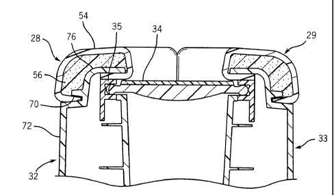
[0023] Fig. 3 is a partial cross-sectional view of center console 20 taken
along a line
5-5 (see Fig. 1) in accordance with an exemplary embodiment. As discussed
above, first side
panel 32 and second side panel 33 can include a rigid outer surface. In an
exemplary
embodiment, the rigid outer surface can act as a substrate for forming first
padded portion 28
and second padded portion 29. As such, first padded portion 28 and second
padded portion
6
CA 02674457 2009-06-30
WO 2008/086089
PCT/US2008/050102
29 are formed without a separate substrate, resulting in a low bulk, cost
efficient design.
Described below is an exemplary process for forming a padded portion on a
substrate. The
process is described in general and with reference to first padded portion 28.
It is to be
understood that the same process can also be used to form second padded
portion 29.
[0024] First padded portion 28 can include an outer cover (or skin) 54. In an
exemplary embodiment, outer cover 54 can be composed of a relatively soft or
flexible
polymeric material such as polyurethane, polyvinylchloride (PVC),
thermoplastic olefin
(TPO), etc. Alternatively, outer cover 54 may be composed of any combination
of polymeric
materials, cloth, leather, composite materials and/or any other materials
which are able to
provide comfort when in physical contact with an individual. In one
embodiment, outer
cover 54 can have a thickness ranging from approximately 0.5 millimeters to
approximately
3.0 millimeters. Alternatively, outer cover 54 may have a thickness ranging
from
approximately 1.0 millimeters to approximately 1.5 millimeters. Alternatively,
any other
thickness may be used. Outer cover 54 can be produced using a slush molding
process, a
vacuum forming process, an injection molding process, an extrusion process, a
casting
process (e.g., gravity casting), or any other suitable process known to those
of skill in the art.
[0025] First padded portion 28 also includes padding (or filler material) 56.
In an
exemplary embodiment, outer cover 54 can be mounted directly to first side
panel 32 such
that a cavity is formed. Padding 56 can be inserted into the cavity between
outer cover 54
and first side panel 32. As such, there is no need for first padded portion 28
to be formed on
an additional substrate which is in turn mounted to first side panel 32.
Elimination of the
additional substrate reduces the weight and cost of first padded portion 28,
simplifies the
manufacturing process, and provides a more aesthetically appealing first
padded portion 28.
In an exemplary embodiment, padding 56 can be a foam or foam-like polymeric
material
such as urethane foam. Alternatively, any other soft or semi-soft material may
be used. In
another exemplary embodiment, padding 56 can be disposed into the cavity
between outer
cover 54 and first side panel 32 in a liquid form. The liquid form can
solidify and/or expand
to fill the cavity. The amount of padding 56 disposed into the cavity can also
be used to
control the softness, structure, and/or shape of first padded portion 28. In
one embodiment,
padding 56 may be configured to bond with outer cover 54 and/or first side
panel 32. The
bond can be through a chemical reaction between padding 56 and outer cover 54
and/or first
7
CA 02674457 2009-06-30
WO 2008/086089 PCT/US2008/050102
side panel 32. Alternatively, the bond can be through an adhesive applied to
padding 56,
outer cover 54, and/or first side panel 32.
[0026] As illustrated with reference to Fig. 3, first side panel 32 includes a
mounting slot 70 configured to receive an edge of outer cover 54. Mounting
slot 70 can be a
tapered slot, groove, or channel which secures outer cover 54 through a
friction or
interference fit. Outer cover 54 can also be frictionally secured between an
interior surface of
first side panel 32 and an upper surface of a first track 35 to which door 34
is mounted. In
alternative embodiments, one or more fasteners such as screws, bolts, rivets,
etc. may be used
alone or in addition to an interference fit to secure outer cover 54 to first
side panel 32.
Alternatively, adhesives, clamps, or any other mounting methods may be used.
In another
alternative embodiment, first side panel 32 may include one or more apertures
configured to
receive portions of outer cover 54 such that outer cover 54 is secured. Outer
cover 54 can be
forced into the one or more apertures through external pressure.
Alternatively, outer cover 54
can be drawn into the one or more apertures using a vacuum. In another
alternative
embodiment, outer cover 54 may extend down and cover a lower portion 72 of
first side
panel 32 such that a larger visible portion of first side panel 32 is covered.
In such an
embodiment, outer cover 54 can be mounted adjacent (i.e., without a cavity
between first side
panel 32 and outer cover 54) to lower portion 72 of first side panel 32 using
adhesive,
fasteners, or any other mounting method. In another exemplary embodiment,
outer cover 54
can be mounted to first side panel 32 in a manner that provides a
substantially airtight and/or
watertight seal from the ambient environment.
[0027] As mounted, outer cover 54 and an upper surface 76 of first side panel
32
form a cavity in which padding 56 is placed. As illustrated in Fig. 3, outer
cover 54 is
mounted to first side panel 32 at two locations such that a single cavity for
receiving padding
56 is formed. In alternative embodiments, outer cover 54 may be mounted to
first side panel
56 in three or more locations such that a plurality of cavities for receiving
padding 56 are
formed. As such, a single outer cover can be used to form a plurality of
distinct padded
portions. Because a single outer cover is used, the plurality of padded
portions have tight,
consistent, and aesthetically pleasing seams. Traditional padded portions,
which included a
separate substrate mounted to a vehicular panel, are not able to achieve such
a tight,
consistent, and aesthetically pleasing appearance.
8
CA 02674457 2009-06-30
WO 2008/086089
PCT/US2008/050102
[0028] A plurality of padded portions may be formed on the substrate by
mounting
the outer cover to the substrate such that a plurality of cavities are formed.
The substrate can
include a plurality of vacuum apertures configured to receive and/or hold
portions of the
outer cover such that the plurality of substantially airtight cavities are
formed between the
substrate and the outer cover. The outer cover can be placed over at least a
portion of the
substrate, and a vacuum box can be used to draw the outer cover into or
adjacent to the
plurality of vacuum apertures in the substrate such that the outer cover is
secured to the
substrate and the plurality of cavities are formed. Alternatively, the outer
cover may be
secured or mounted to the substrate using fasteners, adhesives, or any other
methods. The
padding can be injected, poured, or otherwise inserted into the plurality of
cavities through
one or more padding apertures in the substrate. The padding apertures can be
positioned at
any location on the substrate which provides access to the plurality of
cavities. Because the
outer cover is secured to the substrate in a substantially watertight and
airtight manner, the
padding is not drawn into the vacuum through the vacuum apertures.
[0029] In an exemplary embodiment, a composite/aluminum tool as known to those
of skill in the art can be used to implement insertion of the padding into the
one or more
cavities. Alternatively, any other fill tube, insertion device, nozzle, etc.
can be used. The
substrate may also include one or more vent holes adjacent to the one or more
cavities to
reduce the amount of carbon dioxide or other gas which may accumulate in the
one or more
cavities during the filling operation. Once the padding is inserted into the
one or more
cavities, any vacuum pressure used to secure the outer cover to the substrate
can be removed,
and the outer cover can be mounted to the substrate using adhesives, one or
more fasteners,
and/or a bond formed between the outer cover and the padding. Alternatively,
the outer
cover may be mounted to the substrate prior to applying the vacuum. In another
alternative
embodiment, a vacuum may not be used. In one embodiment, the padded portion
may be
formed using a foam-in-place (FIP) process while the substrate is in a mold
used to form the
substrate. Alternatively, the padded portion may be formed after the substrate
is removed
from the mold. In an alternative embodiment, a self-skinning foam can be used
to form the
padded portion. Self-skinning foam can refer to any foam which forms its own
skin (or outer
cover) upon application, as known to those of skill in the art. The self-
skinning foam can be
applied to the substrate while the substrate is in a mold. In such an
embodiment, an outer
cover is not mounted to the substrate prior to insertion of the self-skinning
foam.
9
CA 02674457 2009-06-30
WO 2008/086089
PCT/US2008/050102
[0030] Fig. 4 is a side elevation view of center console 20 in accordance with
an
exemplary embodiment. As illustrated in Fig. 4, the visible upper surface of
center console
20 is formed in part by an upper surface 80 of first padded portion 28. Upper
surface 80 is
positioned between a rear edge 82 of first padded portion 28 and a front edge
84 of first
padded portion 28. First padded portion 28 is mounted to upper surface 76 of
first side panel
32. Upper surface 80 of first padded portion 28 forms a compound curve having
a convex
portion 42 and a concave portion 44. Concave portion 44 is also formed in part
by an upper
surface of shifter panel 22. As such, upper surface 80 is more highly elevated
(with respect
to a frame or floor of the vehicle) at rear edge 82 of first padded portion 28
than at front edge
84 of first padded portion 28. The higher elevation at rear edge 82 provides
taller individuals
with a higher armrest. Similarly, the lower elevation at front edge 84
provides shorter
individuals with a lower armrest. For example, a tall individual sitting in
the driver seat or
passenger seat of a vehicle is likely to have his/her seat adjusted toward the
rear of the
vehicle (i.e., away from a steering wheel 74) such that he/she has room for
his/her legs.
When the driver seat or passenger seat is adjusted toward the rear of the
vehicle, the tall
individual is positioned such that he/she is able to use the highest part of
first padded portion
28 (or second padded portion 29) as an armrest. As the seat is moved forward
(i.e., toward
steering wheel 74) to accommodate shorter individuals, the seated individuals
are positioned
adjacent to correspondingly lower portions of first padded portion 28 or
second padded
portion 29. As such, center console 20 is able to accommodate individuals of a
plurality of
different sizes without utilizing a bulky, complex adjustment assembly to
raise or lower
center console 20.
[0031] Fig. 5 is an exploded view of a center console in accordance with an
exemplary embodiment. Included in the exploded view are a first side panel 100
having a
first upper surface 102, a second side panel 104 having a second upper surface
106, a rear
panel 108, a shifter panel 110, a beverage holder 112, and an insert 114. The
exploded view
also illustrates a ventilation duct 116, a ventilation cover 118, and a
ventilation control 120.
Ventilation cover 118 and ventilation control 120 are accessible through
apertures in rear
panel 108 such that rear seat passengers can control ventilation. The exploded
view further
illustrates a first track 122, a second track 124, a first door segment 126,
and a second door
segment 128. In an exemplary embodiment, first door segment 126 and second
door segment
128 be mounted in first track 122 and second track 124, and can operate
independently of one
CA 02674457 2009-06-30
WO 2008/086089 PCT/US2008/050102
another. Also illustrated in the exploded view of Fig. 5 is a one-piece outer
cover 130 which
is configured to cover first upper surface 102 and second upper surface 106.
In an exemplary
embodiment, first side panel 100 can be mounted to second side panel 104, and
outer cover
130 can be mounted to first side panel 100 and second side panel 104 such that
a single cavity
is formed. Foam can be inserted into the cavity such that a single padded
portion is formed.
[0032] For purposes of this disclosure, the term "mount" and variations
thereof can
refer to the joining of two components (electrical or mechanical) directly or
indirectly to one
another. Such joining may be stationary in nature or movable in nature. Such
joining may be
achieved with the two components (electrical or mechanical) and any additional
intermediate
members being integrally formed as a single unitary body with one another or
with the two
components or the two components and any additional member being attached to
one
another. Such joining may be permanent in nature such as components which are
molded to
one another, or alternatively may be removable or releasable in nature. As
used in this
disclosure, the term "mount" can include join, unite, connect, associate,
insert, hang, hold,
affix, attach, fasten, bind, paste, secure, bolt, nail, glue, screw, rivet,
solder, weld, and other
like terms.
[0033] The embodiments described herein have been described with reference to
vehicle components. It is important to understand that the components and
methods shown
herein are not limited to vehicular applications. The components and methods
described
herein may also be used in non-vehicle applications such as chairs, desks,
benches, and other
furniture items.
[0034] The foregoing description of exemplary embodiments has been presented
for
purposes of illustration and of description. It is not intended to be
exhaustive or limiting with
respect to the precise form disclosed, and modifications and variations are
possible in light of
the above teachings or may be acquired from practice of the disclosed
embodiments. It is
intended that the scope of the invention be defined by the claims appended
hereto and their
equivalents.
11