Note: Descriptions are shown in the official language in which they were submitted.
CA 02674467 2009-07-03
WO 2008/086223
PCT/US2008/050299
HIGH OUTPUT LOUDSPEAKER
BACKGROUND OF THE INVENTION
1. Technical Field:
The present disclosure relates to a low-frequency sound
reproduction. system. for high power output, and. more particularly
to a low-frequency sound reproduction system having a manifold,
a low frequency speaker, and one or more passive radiators
and/or air ports.
' 2. Discussion of the Related Art:
A woofer is a loudspeaker driver that is designed to
produce low-frequency sounds, typically from around 40 Hertz up
to about a few thousand hertz. Nearly all woofers are driven by
a voice coil in a magnetic field, connected to an amplifier. The
voice coil assembly is an electric motor. When current flows
through the voice coil wire, the coil moves according to
Fleming's left hand rule, causing the coil to push or pull like
a piston. The voice coil is typically cemented to the back of
the speaker cone, which creates sound waves as it is pushed back
and forth.
J.
CA 02674467 2009-07-03
WO 2008/086223
PCT/US2008/050299
A sub-woofer is similar to a woofer, but is dedicated to
the reproduction of bass frequencies, typically from about 20 Hz
to about 200 Hz. Since it is difficult for small loudspeakers to
reproduce frequencies below 80 Hz, especially above 100 dB, a
loudspeaker intended specifically for this task is often used.
There is a growing demand for compact, high-output subwoofer
systems for use in both home and professional settings.
Many existing designs use horn loading to provide high
efficiency and low distortion, but these systems are typically
very large. Shorter horn-loaded systems such as those described
in U.S. Patent No. 5,898,138 detail a method of including
multiple drivers, ports or passive radiators into a single horn
throat- However, the very short nature of the horn severely
restricts the efficiency gain and air load effectiveness at low
frequencies. To obtain better efficiency and still keep a small
enclosure size, some designs use a low frequency horn that is
folded. U.S. Patent No. 4,215,761 relates to a bass sound
projection system which uses a folded horn. While this approach
reduces the overall size of the system, it is still very large
compared to a conventional sealed or ported enclosure.
An alternate solution to standard horn loading is called
"manifolding" and was proposed in U.S. Patent No. 4,733,749.
This design increases efficiency and reduces distortion while
allowing the use of relatively large loudspeakers in a very
2
CA 02674467 2009-07-03
WO 2008/086223
PCT/US2008/050299
compact cabinet. This configuration optionally uses a sealed or
ported cabinet, and the manifold may form the throat of a horn
for even higher performance at the cost of increased size.
Other designs employ multiple chambers in various styles of
bandpass enclosures. These systems can vary in size
significantly, but the smaller designs are usually designed to
have high mid-bass efficiency (50-150 Hz) and sacrifice low
frequency extension. Most commercial applications also have a
severely degraded transient response as a natural result of
high-order upper and lower frequency rolloffs.
Alternate designs use passive radiators (drones) in place
of ports as a method to decrease system size and reduce air
noise inevitable from a standard port. A passive radiator
ideally should be, capable of very high excursion and of
substantially greater surface area than the active woofer. A
known commercial design with such features uses large woofers
and multiple large passive radiators, both of which
significantly increase the size of the speaker system. Another
design uses very compact enclosures with multiple passive
radiators, but these are very low in efficiency and require very
powerful amplifiers to produce meaningful sound pressure level
(SPL).
3
CA 02674467 2009-07-03
WO 2008/086223
PCT/US2008/050299
There exists a need to provide a new loudspeaker system to
provide high output, low distortion, low noise, and extended
frequency response.
SUMMARY OF THE INVENTION
According to an exemplary embodiment of the present
invention there is provided a loudspeaker system which includes
a speaker enclosure having an opening in a front wall, and a
speaker manifold mounted within said enclosure and communicating
with the opening. The speaker manifold includes a pair of
substantially parallel side walls, a back wall, and top and
bottom walls, defining a manifold chamber. The wall opposite the
back wall is substantially open to define a manifold opening and
to permit the communicating. The manifold opening is
substantially in alignment with the front wall opening. A woofer
is mounted on a first wall of the speaker manifold. An acoustic
vent is mounted on a second wall of the manifold, such that the
woofer and the acoustic vent face each other at about a 180
degree angle or about a 90 angle.
According to an exemplary embodiment of the present
invention there is provided a loudspeaker system which includes
a speaker enclosure having a first opening in a first speaker
enclosure wall and a second opening in a second speaker
enclosure wall. A. first speaker manifold is mounted within the
4
CA 02674467 2009-07-03
WO 2008/086223
PCT/US2008/050299
enclosure and communicates with the first speaker enclosure wall
opening. The first speaker manifold includes a pair of
substantially parallel first side walls, a first back wall, and
first top and bottom walls, defining a first manifold chamber.
The wall opposite the first back wall is substantially open to
define a first manifold opening and to permit the communicating.
The first manifold opening= is substantially in alignment with
the first speaker enclosure wall opening. A second speaker
manifold is mounted within the enclosure and communicates with
the second speaker enclosure wall opening. The second speaker
manifold includes a pair of substantially parallel second side
walls, a second back wall, and second top and bottom walls,
defining a second manifold chamber. The wall opposite the second
back wall is substantially open to define a second manifold
opening and to permit the communicating. The second manifold
opening is substantially in alignment with the second speaker
enclosure wall opening. An acoustic vent is mounted on a first
wall of the first speaker manifold and disposed at about a 180
degree or about a 90 degree angle relative to a second wall of
the first speaker manifold. A woofer is mounted on a first wall
of the second speaker manifold and disposed at about a 180
degree angle or about a 90 degree angle relative to a second
wall of the second speaker manifold.
5
CA 02674467 2009-07-03
WO 2008/086223
PCT/US2008/050299
According to an exemplary embodiment of the present
invention there is provided a loudspeaker system which includes
a speaker enclosure having an opening in a front wall, a speaker
manifold mounted within the enclosure and communicating with the
opening. The manifold includes a pair of substantially parallel
side walls, a back wall, and top and bottom walls, defining a
manifold chamber. The wall opposite the back wail is
substantially open to define a manifold opening and to permit
the communicating. The manifold opening is substantially in
alignment with the front wall opening. A first acoustic vent is
mounted on a first wall of the speaker manifold. A second
acoustic vent is mounted on a second wall of the speaker
manifold, such that the first acoustic vent faces the second
acoustic at about a 180 degree angle. A woofer is mounted on a
third wall of the speaker manifold and faces the front wall
opening. The woofer is disposed at about a 90 degree angle
relative to the first and second acoustic vents.
According to an exemplary embodiment of the present
invention there is provided a loudspeaker system which includes
a speaker enclosure having a first opening in a first speaker
enclosure wall and a second opening in a second speaker
enclosure wall. A first speaker manifold is mounted within. the
enclosure and communicates with the first speaker enclosure wall
opening. The manifold includes a pair of substantially parallel
6
CA 02674467 2009-07-03
WO 2008/086223
PCT/US2008/050299
first side walls, a first back wall, and first top and bottom
walls, defining a first manifold chamber. The wall opposite the
first back wall is substantially open to define a first manifold
opening and to permit the communicating. The first manifold
opening is substantially in alignment with the first speaker
enclosure wall opening. A second speaker manifold is mounted
within the enclosure and communicates with the second speaker
enclosure wall opening. The second manifold includes a pair of
substantially parallel second side walls, a second back wall,
and second top and bottom walls, defining a second manifold
chamber. The wall opposite the second back wall is substantially
open to define a second manifold opening and to permit the
communicating to the second speaker enclosure wall opening. The
second manifold opening is substantially in alignment with the
second speaker enclosure wall opening. A first acoustic vent is
munted on a first wall of the first speaker manifold. A second
acoustic vent is mounted on a second wall of the first speaker
manifold, such that the first acoustic vent faces the second
acoustic vent at about a 180 degree angle or about a 90 degree
angle. A woofer is mounted on a first wall of the second speaker
manifold and faces a second wall of the second speaker manifold
at about a 180 degree angle or about a 90 degree angle.
It is to be understood that an "acoustic vent" as used
herein refers to a passive radiator, an air port, or other
7
CA 02674467 2009-07-03
WO 2008/086223
PCT/US2008/050299
similar device. An acoustic vent takes over the output load of a
woofer at low frequencies and provides much of the output. The
acoustic vent and enclosure airspace combine at a certain
frequency to resonate, and the woofer drives the resonance. At
a range of frequencies around this resonance, the acoustic vent
moves much more than the woofer.
BRIEF DESCRIPTION OF THE DRAWINGS
Exemplary embodiments of the invention can be understood in
more detail from the following descriptions taken in conjunction,
with the accompanying drawings in which:
FIGs. 1(a)-(o) illustrate a top cross-section, side cross-
section and front view of a loudspeaker system, respectively
according to an exemplary embodiment of the present invention.;
FIGs. 2(a)-(c) illustrate a top cross-section, side cross-
section and front view of the loudspeaker system of FIG. 1,
respectively where the passive radiator has been replaced with
an air port, according to an, exemplary embodiment of the present
invention;
FIGS. 3(a)-(c) illustrate a side top section, side cross-
section and front view of a loudspeaker system, respectively
according to an exemplary embodiment of the present invention;
8
CA 02674467 2009-07-03
WO 2008/086223
PCT/US2008/050299
FIGs. 4(a)-(c) illustrate a top cross-section, side cross-
section and front view of a loudspeaker system, respectively
according to an exemplary embodiment of the present invention;
FIGs. 5(a)-(c) illustrate a top cross-section, side cross-
section and front view of a loudspeaker system, respectively
according to an exemplary embodiment of the present invention;
FIG. 6 is a graph illustrating the output efficiency of the
loudspeaker system illustrated in FIG. 4 as compared to
conventional loudspeaker systems;
FIG. 7 is a relative graph of the maximum linear output
sound pressure level of the loudspeaker system referenced in
FIG. 6 as compared to conventional loudspeaker systems;
FIGs. 8(a)-(b) illustrate a top cross-section and side
cross-section, respectively, of a conventional loudspeaker
system having a compact design; and
FIGs. 9(a)-(b) illustrate a top cross-section and side
cross-section, respectively, of a conventional loudspeaker
system having a sub-compact design.
DETAILED DESCRIPTION OF THE EXEMPLARY EMBODIMENTS
Exemplary embodiments of the present invention will be
described below in more detail with reference to the
accompanying drawings. This invention may, however, be embodied
in different forms and should not be construed as limited to the
9
CA 02674467 2009-07-03
WO 2008/086223
PCT/US2008/050299
embodiments set forth herein. Rather, these embodiments are
provided so that this disclosure will be thorough and complete,
and will fully convey the scope of the invention to those
skilled in the art.
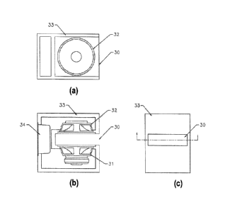
FIG. 1 illustrates different views of a loudspeaker system,
according to an exemplary embodiment of the present invention.
FIG. 1(a) illustrates a top cross-section of the present
exemplary embodiment. FIG. 1(b) illustrates a side cross-section
of the present exemplary embodiment. FIG. 1(c) illustrates a
front view of the present exemplary embodiment.
Referring to FIG. 1, the loudspeaker system has a speaker
enclosure 33 which includes a manifold 30, a woofer 31, a
passive radiator 32, and a power amplifier 34. The enclosure 33
(also known as a cabinet) is hollow and may be made out of wood,
metal or any other suitable material.
The manifold 30 is essentially a well in the enclosure 33
having a pair of substantially parallel side walls, a back wall,
a top wall, and a bottom wall, forming a manifold chamber. The
wall opposite the back wall is substantially open to define a
manifold opening.
The woofer 31 is mounted on a first wall of the manifold.
The passive radiator 32 is mounted on a second wall of the
manifold 30, such that the woofer 31 and the passive radiator 32
CA 02674467 2009-07-03
WO 2008/086223
PCT/US2008/050299
face each other at about a 180 degree angle or about a 90 degree
angle (not shown).
A surround of the woofer 31 may be adjacent to the first
wall of the manifold 30 and a surround of the passive radiator
32 may be adjacent to the second wall of the manifold 30. The
surround of the woofer may be partially covered by the speaker
enclosure 33.
The woofer 31 and the passive radiator 32 may be separated
from one another by a distance which may be determined through
experimentation by varying the dimensions of the manifold. The
dimensions of the manifold 30 may be optimized to improve low
frequency efficiency and distortion characteristics, and may
vary considerably depending on the woofer/passive radiator
suspension characteristics and desired bandwidth of the system.
The woofer 31 is an active woofer and may be of a
conventional high excursion design. The passive radiator 32 is
optionally oval in shape to save in cabinet volume. The oval
design allows for the highest overall surface area while keeping
the total depth of the cabinet to a minimum. It also reduces the
overall length of the manifold section, which helps to prevent
any standing wave resonances that may otherwise exit.
Embodiments of the present invention, however, are not limited
to oval shaped passive radiators or woofers, as each may be
shaped as a circle, a rectangle, a square, or any other suitable
11
CA 02674467 2009-07-03
WO 2008/086223
PCT/US2008/050299
shape. The dimensions of the passive radiator 32 illustrated in
FIG. 1 may be, for example, an oval of ten inches by eight
inches. However, the dimensions of the. woofer 31 and passive
radiator 32 may vary considerably. Although FIG. 1 illustrates
using a passive radiator 32 as an acoustic vent, the passive
radiator 32 may be replaced with an air port of suitable length
and diameter. The length and diameter of the air port may be
determined through experimentation and adjusted as necessary.
The power amplifier 34 is optionally part of the enclosure
33 since the loudspeaker system may be. adapted to use an
external power amplifier. The power amplifier may be class A,
class AB, class D, class H., or any other suitable type. The
power amplifier may have active electronics processing for
equalization, low-pass and high-pass crossovers and output
limiters to prevent woofer damage or excessive distortion.
FIG. 2 illustrates a different configuration of the
loudspeaker system. of FIG. 1, where the passive radiator 32 has
been replaced with an air port 43, according to an exemplary
embodiment of the present invention. FIG. 2(a) illustrates a top
cross-section of the present exemplary embodiment. FIG. 2(b)
illustrates a side cross-section of the present exemplary
embodiment. FIG. 2(c) illustrates a. front view of the present
exemplary embodiment.
12
CA 02674467 2009-07-03
WO 2008/086223
PCT/US2008/050299
Referring to FIG. 2, the loudspeaker system includes an
enclosure 42 having an air port 43, a woofer 41, a manifold 40,
and a power amplifier 44. While an opening of the air port 43 is
illustrated as facing the woofer 41 at an angle of about 180
degrees, the woofer may also- be adjusted to face the air port 43
at an angle of about 90 degrees (not shown). The air port 43,
having a. predetermined diameter extends into the enclosure 42
for a predetermined length. The length and diameter of the air
port can be determined through experimentation.
FIG. 3 illustrates different views of a. loudspeaker system,
according to an exemplary embodiment. of the present invention.
FIG. 3(a) illustrates a top cross-section of the present
exemplary embodiment. FIG. 3(b) illustrates a side cross-section
of the present exemplary embodiment. FIG. 3(c) illustrates a
front view of the present exemplary embodiment.
Referring to FIG. 3, the loudspeaker system includes an
enclosure 3 having a passive radiator manifold 5, a woofer
manifold 6, a passive. radiator 2, a woofer 1, and a power
amplifier 4. The passive radiator manifold 5 and the woofer
manifold 6 are similar to the manifolds illustrated in FIGS. 1-
2. The structure of the components that make up this embodiment,
such as the passive' radiator 2, the woofer 1, and amplifier are
similar to those discussed above in FIGS. 1-2.
13
CA 02674467 2009-07-03
WO 2008/086223
PCT/US2008/050299
The passive radiator 2 is mounted to a first side of the
passive radiator manifold 5, such that it faces a second side of
the passive radiator manifold 5 at about a 180 degree angle or
about a 90 degree angle (not shown). The woofer 1 is mounted to
a first side of the woofer manifold 6, such that it faces a
second side of the woofer manifold 6 at about a 180 degree angle
or about a 90 degree angle (not shown).
A passive radiator manifold opening or exit of the passive
radiator manifold 5 may be on the same side of the enclosure 3
as an exit of the woofer manifold 6 or may optionally exit on a
different surface.
The passive radiator 2 may be a predetermined distance away
from one side of the enclosure 3 based on the size of the
passive radiator manifold 5. The woofer 1 may be a predetermined
distance away from a side of the enclosure 3 based on the size
of the woofer manifold 6. These distances can be determined
through experimentation by varying the dimensions of the passive
radiator manifold 5 and the woofer manifold 6 as discussed in
connection with the manifold 30 illustrated in FIG. 1 above.
A surround of the passive radiator 2 may be adjacent to a
side of the passive radiator manifold 5. A surround of the
woofer may be adjacent to a side of the woofer manifold. The
surround of the woofer may be partially covered by the enclosure
3.
14
CA 02674467 2009-07-03
WO 2008/086223
PCT/US2008/050299
As discussed above for FIG. 1, the power amplifier is
optional and the passive radiator 2 may be replaced with an air
port.
FIG. 4 illustrates a loudspeaker system, according to an
exemplary embodiment of the present invention. FIG. 4(a)
illustrates a top cross-section of the present exemplary
embodiment. FIG. 4(b) illustrates a side cross-section of the
present exemplary embodiment. FIG. 4(c) illustrates a front view
of the present exemplary embodiment.
Referring to FIG. 4, the loudspeaker system includes an
enclosure 13, having a woofer 11, a first passive radiator 12, a
second passive radiator 14, and a manifold 10. The manifold 10
is similar to the manifolds illustrated in FIGs. 1-3. The
structure of the components that make up this embodiment, such
as the passive radiators 12 and 14, and the woofer 11 are
similar to those discussed above in FIGS. 1-3-
The first passive radiator 12 faces towards the second
passive radiator 14 at an angle of about 180 degrees. The
distance between the first passive radiator 12 and the second
passive radiator 14 depends on the dimensions of the manifold 10
and can be adjusted through experimentation. The woofer 11 is
arranged at about a 90 degree angle with respect to the first
passive radiator 12 and the second passive radiator 14.
CA 02674467 2009-07-03
WO 2008/086223
PCT/US2008/050299
A surround of the first passive radiator 12 may be adjacent
to a first side of the manifold 10. A surround of the second
passive radiator 14 may be adjacent to a second side of the
manifold 10. A surround of the woofer 11 may be adjacent to a
third side of the manifold. The woofer surround may be partially
covered by the walls of the manifold without ill effect. In some
instances, the entire surround and a portion of the cone may be
shaded by the enclosure construction, in a similar manner to
compression phase plugs in high-frequency horn transducers. This
serves to improve the coupling efficiency in addition to the
gains from manifolding.
As in the previous embodiments, the power amplifier is
optional and the passive radiators 12 and 14 may be replaced
with an air port.
FIG. 5 illustrates a loudspeaker system, according to an
exemplary embodiment of the present invention. FIG. 5(a)
illustrates a top cross-section of the present exemplary
embodiment. FIG. 5(b) illustrates a side cross-section of the
present exemplary embodiment. FIG. 5(c) illustrates a front view
of the present exemplary embodiment.
Referring to FIG. 5, the loudspeaker system has an
enclosure 25 which has a first passive radiator 23, a second
passive radiator 24, passive radiator manifold 22, a woofer 21,
a woofer manifold 20, and a power amplifier 26. The passive
16
CA 02674467 2009-07-03
WO 2008/086223
PCT/US2008/050299
radiator manifold 22 and the woofer manifold 20 are similar to
the manifolds illustrated in the previous figures. The structure
of the components that make up this embodiment, such as the
passive radiators 23 and 24, the woofer 21, and the amplifier 26
are similar to those discussed in the previous figures.
The first passive radiator 23 faces towards the second
passive radiator 24 at an angle of about 180 degrees or about 90
degrees (not shown). The first passive radiator 23 and the
second passive radiator 24, are mounted respectively to a first
and second wall of the passive radiator- manifold 22. A surround
of the first passive radiator 23 may be adjacent to a first side
of the passive radiator manifold. A surround of the second
passive radiator 24 may be adjacent to a second side of the
passive radiator manifold. A surround of the woofer 21 may be
adjacent to a side_ of the woofer manifold 20. The surround of
the woofer 21 may be partially covered by the enclosure 25.
As in the previous figures, the power amplifier 26 is
optional and each of the passive radiators 23. and 24 may be
replaced with an air port.
It should be noted that while all of the previously
discussed embodiments have been illustrated with one or two
manifolds, the present invention_ is not limited to any
particular number of manifolds. As an example, a third manifold
could be added to the loudspeaker system illustrated in FIG. 5.
17
CA 02674467 2009-07-03
WO 2008/086223
PCT/US2008/050299
Additionally, passive radiators, air ports, and woofers, could
be mounted to sides of the third manifold.
In operation, the interaction of an enclosure having a
woofer, a passive radiator, and a manifold vary based on
frequency. At upper frequencies, substantially- above the
resonant frequency of a enclosure/passive radiator combination,
the woofer cone is loaded in a small chamber, which provides an
improvement in the actual air displacement, and provides actual
acoustic output. The cone can get a smaller volume of air moving
easier than making the air in an entire living room. This shows
up as an acoustic resistance that acts against the cone's
excursion. Design of the passive radiators is very important at
these upper frequencies because if the passive radiators move
much, they will absorb some of the acoustic output of the active
woofer. This is because the improved efficiency of coupling the
woofer to the manifold's air also means that the air is
efficiently coupled to the front of the passive radiators. At
frequencies just above to just below the enclosure resonance,
the internal resonance of the enclosure is very effective at
controlling the cone motion. At frequencies below the resonance,
the manifold provides an acoustic resistance that is not seen in
conventional enclosures. The acoustic resistance of the manifold
tends to limit the maximum motion of the cones, which keeps
18
CA 02674467 2009-07-03
WO 2008/086223
PCT/US2008/050299
distortion down and helps the mechanical reliability of the
components.
FIG. 6 is a graph illustrating the output efficiency of an
embodiment of the loudspeaker system illustrated in FIG. 4 as
compared to a conventional compact loudspeaker system
illustrated in FIGs. 8(a)-(b), and a conventional sub-compact
loudspeaker system illustrated in FIGS. 9(a)-(b). FIG 8(a) and
FIG. 8(b) illustrate a top cross-section and side cross-section,
respectively, of a conventional compact loudspeaker system. The
compact loud speaker system includes a passive radiator 52, a
woofer 51, an enclosure 53, and a power amplifier 53. FIG. 9(a)
and FIG. 9(b) illustrate a top cross-section and side cross-
section, respectively, of a conventional sub-compact loudspeaker
system. The sub-compact loudspeaker system includes a passive
radiator 62, a woofer 61, an enclosure 63, and a power amplifier
64.
Referring to FIGs. 6, 8(a)-(b), and 9(a)-(b), the output
efficiency of a conventional loudspeaker system having a compact
design with a round ten inch diameter passive radiator 52 is
illustrated by a dotted curve, the output efficiency of a
conventional loudspeaker system having a sub-compact design with
a round ten inch diameter passive radiator 62 is illustrated by
a dashed curve, and the output efficiency of an embodiment of
the loudspeaker system illustrated in FIG. 4 having two oval ten
19
CA 02674467 2009-07-03
WO 2008/086223
PCT/US2008/050299
inch by eight inch passive radiators is illustrated by the solid
curve. As shown in FIG. 6, the embodiment of the present
invention illustrated outperforms the conventional designs by
several dB, particularly over the 20 to 100 Hz frequency range.
FIG. 7 is a relative graph of the maximum linear output
sound pressure level of the embodiment of the loudspeaker system
referenced in FIG. 6 as compared to the conventional loudspeaker
systems of FIGs. 8(a)-(b), and FIGS. 9(a)-(b).
Referring to FIG. 7, the curve of the conventional compact
loudspeaker system having a round ten inch diameter passive
radiator 52 is marked with diamonds, the curve of the
conventional subcompact loudspeaker system having a round ten
inch diameter passive. radiator 62 is marked with squares, and
the manifolded dual oval ten. inch by eight inch passive radiator
embodiment is marked with Xs. The manifolded design generally
outperforms the conventional designs between the pictured 20 and
125 Hz range. Between 25 and 50 Hz, the manifolded design
outperforms the conventional designs by at least 2-3 dB and at
some frequencies by as much as 4-6 dB.
Although the illustrative embodiments have been described
herein with reference to the accompanying drawings, it is to be
understood that the present invention is not limited to those
precise embodiments, and that various other changes and
modifications may be affected therein by one of ordinary skill
CA 02674467 2014-02-20
in the related art, and furthermore that the scope of the claims should not be
limited by the
preferred embodiments set forth in the examples, but should be given the
broadest interpretation
consistent with the description as a whole.
21