Note: Descriptions are shown in the official language in which they were submitted.
CA 02674528 2009-06-22
WO 2008/079032 PCT/NZ2007/000391
GAS DETECTOR
FIELD OF THE INVENTION
The present invention relates to a gas detector for sensing the concentration
of inultiple
target gases in an environment. In particular, althougli not exclusively, the
environment is a
confined space or other such space where the target gases may
congregate/concentrate.
BACKGROUND TO THE INVENTION
Various types of gas detectors are available, including catalytic, bead
(pellistor) gas
detectors, electrocliemical cell based gas detectors, photo-ionisation gas
detectors, and laser
spectroscopy gas detectors, such as laser diode spectxoscopy (LDS) gas
detectors for
example.
LDS gas detectors utilise laser diodes that transmit radiation at wavelengths
that
correspond to the optical absorption lines of the target gases being detected
in the
enviroriment. An optical detector senses the radiation that is transinitted
through a gas
sample of the environment so that the concentration or quantity of the target
gas can be
determined based on theintensity of the radiation received with the target gas
present and
the transmitted intensity without the target gas. One such LDS gas detector
design is
described in international PCT patent application publication WO 2005/08827.5.
In this specification where reference has been made to patent specifications,
other=external
documents, or other sources of information, this is generally for the purpose
of providing a
context for discussing the features of the invention. Unless specifically
stated othei.-wise,
reference to such external docuinents is not to be construed as an admission
that such
docuinents, or such sources of information, in any jurisdiction, are prior
art, or forin part
of the coinmon general Imowledge in the art.
It is an object of tlie present invention to provide a gas detector for
sensing the
concentration of inultiple target gases within a gas sainple from a
surrounding
environment, or to at least provide the public with a useful choice.-
1
CA 02674528 2009-06-22
WO 2008/079032 PCT/NZ2007/000391
SUMMARY OF THE INVENTION
In a first aspect, the present invention broadly consists in a gas detector
that is arranged to
sense the concentration levels of target gases ox-ygen, methane, carbon
monoxide, and
hydrogen.sulphide, within a gas sainple from an environinent surrounding the
detector,
comprising: a laser source or sources that is/are arranged to translnit
radiation through the
gas sainple at four target wavelengths that correspond approximately to the
optimu.in
absorption wavelengths of each of the target gases; an optical detector or
detectors that are
arranged to sense the intensity of the radiation tiansmitted through the gas
sample at each
of the target wavelengths; and a control. system that is arranged to operate
the laser
source(s) and optical detector(s), and which generates representative
concentration level
information relating to each of the target gases within the gas sample based
on the level of
absorption of the radiation transmitted into the gas sample at each of the
target
wavelengths.
Preferably, the control system is arranged to dete.tznine ditect absorption
levels based on
the intensity of the radiation received by the optical detector(s) relative to
the intensity of
the radiation transinitted by the laser source(s) at each of the target
wavelengths.
Preferably, the laser source(s) are arranged to transmit radiation in the
infrared band. In
one form, the laser source(s) are arranged to transmit radiation in the
wavelength range of
between about 760nin and about 1700nm. In another form, the laser source(s)
are arranged
to transmit the radiation in the wavelength range of between about 2 m and
about 6 m.
Preferably, the laser source(s) are laser diodes(s).
In one forin, the gas detector comprises four laser sources, each of which is
arranged to
transmit radiation at one of the target wavelengths corresponding to one of
the target
gases. Preferably, each of the four laser sources are laser diodes of either
vertical-cavity
surface-emitting laser (VCSEL) or distributed feedback laser (DFB) type.
2
CA 02674528 2009-06-22
WO 2008/079032 PCT/NZ2007/000391
In one form, the four laser sources coinprise one VCSEL laser diode that is
arranged to
transinit radiation at the target wavelength corresponding to oxygen and three
DFB laser
diodes that are arranged to transmit radiation at the respective target
wavelengths of
methane, carbon monoxide, and hydrogen sulphide. In another forin, the four
laser
sources comprise four VCSEL laser diodes that are arranged to tiansrnit
radiation at the
respective target wavelengths of oxygen, methane, carbon monoxide and hydrogen
sulphide.
In one form, the gas detector comprises a single optical detector that is
arranged to sense
the intensity of radiation transmitted th.tough the gas sample at all of the
target wavelengths
of the target gases.
In another form, the gas detector comprises a first optical detector that is
arranged to sense
the intensity of radiation transmitted through the gas sample at the target
wavelength of
methane, carbori monoxide and hydtogen sulphide, and a second optical detector
that is
arranged to sense the intensity of the radiation transmitted through the gas
sample at target
wavelength of oxygen. Preferably, the first optical detector is a germanium
(Ge)
photodiode and second optical detector is a silicon (Si) photodiode.
Preferably, the optical detector(s) are photodiode(s).
In one form, the control syste.n comprises a single current driver for driving
the laser
source(s). Preferably, there are four laser sources, each of which is arranged
to transmit
radiation at one of the target wavelengths corresponding to one of the target
gases, and
25. wherein the single current dtiver is arranged to drive all four laser
sources.
In another form, there are four laser sources, each of which is arranged to
transmit
radiation at one of the target wavelengths corresponding to one of the target
gases, and
wherein the control system coznprises a plurality of current drivers, each
current driver
driving one or more of the four laser sources.
Preferably, the laser source(s) are driven by one or rnore current drivers.
3
CA 02674528 2009-06-22
WO 2008/079032 PCT/NZ2007/000391
In one form, the control system is arranged to operate the current driver(s)
to activate all
laser sources concurrently and continuously. Preferably, the current driver(s)
of the control
system are arranged to drive thelaser source(s) with continuous drive
currents.
In another form, the control systein is' arranged to control the current dt-
iver(s) to activate
each laser source sequentially in a pre-deterxnin.ed pattern in a cyclical
inanner one at a
time. Preferably, the current driver(s) of the control system are arranged to
drive the laser
source(s) in a pre-deterlnined pattern via pulsed drive currents.
Preferably, the current driver(s) of the control system are arranged to drive
the laser
source(s) using di7ve currents that are modulated with a sine wave and a
triangle wave such
that the signals are simultaneously triangularly ramped and sinusoidall.y
inodulated. More
preferably, the current driver(s) of the control system are arranged to
generate current drive
signals in the forin of pulses that are triangularly ramped and sinusoidally
modulated.
Preferably, the control system further comprises a lock-in amplifier or
amplifiers that are
arranged to amplify or fzlter an output intensity signal from the optical
detector(s) at each
of the target wavelengths of the target gases.
In one form, the gas detector coinprises a single optical detector and wherein
the control
systein compi.-ises a single lock-irn aa.nplifier that is operated to amplify
and filter the output,
intensity signal froin the optical detector at each of the target wavelengths,
one target
wavelength at a time to correspond with radiation wavelengths transmitted by
the laser
source (s) .
Preferably, the control system further comprises a temperature control module
or modules
that are arranged to sense and control tlie operating temperature(s) of the
laser source(s).
More preferably, the temperature control module(s) are arranged to maintain
the operating
temperature of the laser source(s) at pre-determined temperature(s) that are
required for
transmission of radiation at the target wavelengths.
Preferably, there are four laser sources and four independent temperature
control modules,
one for each laser source.
4
CA 02674528 2009-06-22
WO 2008/079032 PCT/NZ2007/000391
Preferably, the gas detector further coinprises a gas space through which a
gas sample froin
the environment may pass, the laser source(s) and optical detector(s) being
arranged about
the gas space such that the laser source(s) transmit radiation through the gas
space for
detection by optical detector(s).
Preferably, the radiation at one or more of the target wavelengths is
transinitted from the
laser source(s) directly through the gas space to the optical detector(s).
Preferably, the laser source(s) transrnitting radiation at the target
wavelengths of oxygen
and methane are arranged to transmit the radiation ditectly through the gas
sample to the
optical detector(s).
Preferably, the radiation transmission path length between the laser source
transmitting at
the target wavelength of oxygen and the optical detector(s) is in the range of
about 0.01m
to about 0.1m. More preferably, the radiation transmission path length between
the laser
source translnitting at the target wavelength of oxygen an the optical
detector(s) is
approximately 0.05m.
Preferably, the radiation transmission path length between the laser source
transmitting at
the target wavelength for methane and the optical detector(s) is in the range
of about
0.05m to about 0.2m. More preferably, the radiation transmission path length.
between the
laser source transmitting at the target wavelength of inethane and the optical
detector(s) is
approximately 0.1 m.
Preferably, the gas space comprises an optical system and wherein the
radiation at one or
more of the target wavelengths is indirectly transinitted from the laser
source(s) to the
optical detector(s) via the optical system, the optical system being arranged
to inodify and
increase the radiation transinission path length at those target wavelengths
relative to a
direct transinission through the gas space.
5
CA 02674528 2009-06-22
WO 2008/079032 PCT/NZ2007/000391
Preferably, the laser source(s) ttansinitting at the target wavelengths of
carbon monoxide
and hydrogen sulphide are arranged to direct the radiation inditectly to the
optical
detector(s) via the optical system.
Preferably, the radiation transmission path length from the laser source
tiansmitting at the
target wavelength of carbon monoxide and the optical detector(s), after
transmission
through the optical system, is in the range of about 20m to about 50m. More
preferably,
the radiation transmission path length between the laser source transinitting
at the target
wavelength of carbon monoxide and the optical detector(s), after transmission
through the
optical system, is approximately 30m.
Preferably, the radiation transmission path length from the laser source
transmitting at the
target wavelength of hydrogen sulphide and the optical detector(s), after
transmission
through the optical system, is in the range of about lOm to about 35m. More
preferably,
the radiation transmission path length froin the laser source transinitting at
the target
wavelength of hydrogen sulphide and the optical detector(s), after
ttansmission through the
optical systein, is approximately 20m.
Preferably, the optical system in the gas space comprises a multi-pass cell
having an input
aperture through which radiation from the laser source(s) enters the cell and
an output
aperture through which the radiation exits the cell for detection by the
optical detector(s),
the ceIl further comprising reflecting surfaces that are arranged to reflect
the radiation back
aiid forth within the cell multiple times to extend the radiation transmission
path length
through the gas sample within the cell before the radiation exits the cell
through the output
aperture.
Preferably, the multi-pass cell of the optical system comprise two spaced-
apart reflecting
surfaces that are arranged to reflect the radiation entering the cell through
the input
aperture back and forth between the surfaces multiple tttnes before directing
the radiation
to exit the cell through the output aperture.
In one form, the reflecting surfaces of the inulti-pass cell are planar
inv:rors.
6
CA 02674528 2009-06-22
WO 2008/079032 PCT/NZ2007/000391
In another form, the reflecting surfaces of the multi-pass cell are curved
mirrors. The
curved mirrors of the x.nulti-pass cell may be in the forn7 of spherical
concave iniuors.
Alternatively, the curved initrors of the multi-pass cell may be in the form
of cylindrical
concave mirrors.
Preferably, the input and output apertures of the .inulti-pass cell of the
optical system may
be the same aperture of separate apertures.
Preferably, the multi-pass cell of the optical system is arranged to receive
two or more
radiation beams at two or more of the target,wavelengths.
Preferably, the multi-pass cell of the optical systein is arranged to reflect
the radiation
within the cell in a zig-zagged path in the cell before directing the
radiation to exit the cell
via the output apertuxe.
Preferably, the gas detector is in the form of a hand-held device having a
housing within
which the components are securely mounted and an aperture within the housing
through
which the gas saa.nple from th.e environinent may flow.
Preferably, the control systezn further comprises an output display for
displaying the
concentration levels of the target gases within tlle sainple.
Preferably, the control system coinprises an alar:m or alarms that are
arranged to
automatically trigger should the concentration levels of one or more of the
target gases
within the gas sample rise above or fall below predeterinined maximum and
ininirnum
thresholds, the alarm(s) being any one or inore of the following types:
audible, visual,
andJor tactile.
Preferably, the target wavelength transmitted for detecting oxygen is in the
range of about
760n.in to about 766nm. More preferably, the target wavelength transmitted for
detecting
oxygen is approximately 764nm.
7
CA 02674528 2009-06-22
WO 2008/079032 PCT/NZ2007/000391
Preferably, the target wavelength transmitted for detecting carbon monoxide is
in the range
of about 1560nm to about 1600nm. More preferably, the target tvavelength
trailsmitted for
detecting carbon monoxide is approximately 1565ntn.
Preferably, the target wavelength transiizitted for detecting metliane is in
the range of about
1630nm to about 1670nm. More preferably, the target wavelength transmitted for
detecting
methane is approximately 1665nm.
Preferably, the target wavelength transmitted for detecting hydrogen sulphide
is in the
range of about 1560nrn to about 1600nm. More preferably, the target wavelength
transmitted,for detecting hydiogen sulpliide is approximately 1576nm:
In a second aspect, the present invention broadly consists in a gas detector
that is arranged
to sense the concenttation levels of a plurality of target gases within a gas
sample from an
envitonment surrounding the detector, comprising: a laser source or sources
that is/are
arranged to transmit radiation through the gas sample at target wavelengths
that
correspond appioximately to the optimum absoiption wavelengtlls of each of the
target
gases; an optical detector or detectors that are arranged to sense the
intensity of the
radiation transmitted through the gas sample at each of the target
wavelengths; and a
control system that is arranged to operate the laser source(s) and optical
detector(s), and
which generates representative concentration level information relating to
eacli of the,
target gases within the gas sample based 'on the level of absorption of the
radiation
transn-zitted into the gas sample at each of the target wavelengths.
Preferably, .the target gases may comprise any two or more of the target
gases: oxygen,
inethane, carbon monoxide, hydrogen sulphide, a.intnonia, water, acetylene,
carbon dioxide,
nitrogen oxide, ethylene, and nitrogen dioxide.
The second aspect of the invention .tnay comprise any one or more of the
features outlined
above in respect of the first aspect of the invention.
The tei7n "gas sample" is intended to cover any volume of gas or mixture of
gases, typically
air, from the environment surround.ing the gas detector.
8
CA 02674528 2009-06-22
WO 2008/079032 PCT/NZ2007/000391
The term "comprising" as used in this specification means "consisting at least
in part of".
When interpreting each statement in this specification that includes the terin
"comprising",
features other than that or those prefaced by the term may also be present.
Related terms
such as "comprise" and "comprises" are to be interpreted in the same inanner.
The invention consists in the foregoing and also envisages constructions of
which the
following gives examples only.
BRIEF DESCRIPTION OF THE DRAWINGS
Preferred emboditnents of the invention will be described by way of example
only and with
reference to the drawings, in which:
Figure 1 is a scheinatic diagram of a first preferred form gas detector of the
.invention;
Figure 2 is `a schematic diagrain of the current dtiver for the laser sources
of the fi.tst
preferred form gas detector;
Figure 3 is a glaphical representation of sequential pulsed drive currents
generated by the
current driver of first preferred form gas detector;
Figure 4 is a schematic diagram of a lock-in amplifier that amplifies and
filters intensity
output sig .zals from the optical detector of the first preferred forin gas
detector;
Figure 5a is a schematic diagram of the closed loop temperature control
impleinented by
temperature control inodules of the fust preferred forin gas detector;
Figure 5b is a schematic diagram of a temperature control module of the first
preferred
form gas detector;
Figure 6 is a schematic diagram of a second preferred forin gas detector of
the invention;
Figure 7 is a schematic diagram of the current drivers for the laser sources
of the second
preferred forin gas detector;
Figure 8 is a schematic diagi:am of the signal processing modules for the
optical detectors
of the second preferred form gas detector;
Figure 9 is a schematic diagram of a lock-in amplifier that ainplifies and
filters intensity
output signals from the signal processing inodules of the second preferred
foi7n gas
detector;
9
CA 02674528 2009-06-22
WO 2008/079032 PCT/NZ2007/000391
Figure 10 is a schematic diagrain of a temperature control module of the
second preferred
forin gas detector;
Figure 11 is a schematic diagram of the main controller of the-second
preferred form gas
detector interfacing with main subsystems of the detector;
Figure 12 is a schematic diagram of a third preferred form gas detector of the
invention;
Figure 13 is a schematic diagram of the current driver for the laser sources
of the third
preferred form gas detector;
Figure 14 is a schematic diagram of an arrangement of laser sources and
optical detectors
for the second or third preferred forms of the gas detector, including an
optical system
having a multi-pass cell with planar mirrors;
Figure 15 is a schematic diagram of an arrangement of laser sources.and
optical detectors
for another possible form of the gas detector, including an optical system,
having a multi-
pass cell with spherical concave mirrors and a single input/output aperture;
Figure 16 is a schematic diagram of an arrangement of laser sources and
optical detectors
for another possible form of the gas detector, including an optical system
having a lnulti-
pass cell with spherical concave inirrors and two input/output apertures;
Figure 17a is a schematic diagram of an arrangement of laser sources and
optical detectors
for another possible form of the gas detector, including an optical system
having a inulti-
pass cell with cylindrical concave mirrors;
Figure 17b is the perspective view of the cylindrical concave mirrors of the
optical system
shown in Figure 17a and in particular showing the reflection of laser light
between the.
cylindrical concave mirrors; and
Figure 17c is a diagrain showing the rotation of the cyli.ndrical concave
mirrors of the
optical system of figure 17a relative to each other.
DETAILED DESCRIPTION OF PREFERRED EMBODIMENTS
The present invention relates to a gas detector.for sensing and determirnin.g
representative
concentrations or quantity levels of multiple target gases within an
envitonment. In
particular, the gas detector is arranged to sense a plurality of target gases
in a gas sample
from the environment surrounding the detector. The target gases may coinprises
any two
or inore of the following gases: oxygen, carbon monoxide, methane, hydrogen
sulphide,
ammonia, watet, acetylene, carbon dioxide, hydrogen cyanide, chlorine,
ethylene, i.nethyl
CA 02674528 2009-06-22
WO 2008/079032 PCT/NZ2007/000391
broinide, nitrogen oxide, and nitrogen dioxide, or any gas that has suitable
absorption
features in the infrared band. The concentration levels of the target gases
are determined
using laser spectroscopy. This. involves directing electromagnetic radiation,
such as
infrared light,. through the gas sample at specific target wavelengths that
coriespond
approximately to deterinined optimusn'absorption wavelengths for each of the
target gases
and then sensing the intensity of the radiation transmitted through the gas -
sample at each
of the target wavelengths. Representative concentration levels for each target
gas in the gas
sainple may then be calculated based on the level of absorption of the
radiation transmitted
into the gas sample at each of the target wavelengths. As mentioned, the
electromagnetic
radiation may be in the infrared band. Byway of example, the radiation may be
in the
wavelength range of 760 - 1700nm, or alternatively in the wavelength range of
2-6 rn, or
any other suitable range in the infrared band:
The gas detector 'is preferably portable and hand-held such that it may be
carried by a user
tliat is working in a confined space that may potentially contain, or be
subject to, a build-up
of hazardous gases, such as carbon monoxide, methane, hydrogen sulphide,
ammonia and
the like, or a diminished supply of breathable oxygen or a dangerously high
oxygen
concentration that presents an explosive risk. In operation, the gas detector
is arranged to
interrogate a gas sample witlzrn the surrounding environment to assess the
concenttation
levels, for example parts-per-inillion (ppin) levels of the target gases with
respect to air or
anotlier gas withi.n the environment, and continuously display those levels to
the user.
Additionally or alternatively, the gas detector inay be arranged to compare
the sensed
concentration levels with predeteiinined maxitnum or minimum threshold levels
and alerts
the user, via an audible and/or visual and/or tactile alarm or alarms, should
a breach of the
threshold levels occur. For exainple, the alarm of tlie gas detector may be
triggered if the
concentration levels of carbon monoxide, methane, hydrogen sulphide or ammonia
exceed
maximum preset thresholds that znay pose a danger to a user. Likewise, the
alarin(s) may be
triggered if the oxygen concentration level declines below a minimum preset
threshold such
that a user may not be able to safely breathe within the environment or if the
concentration
level increases to a point tliat presents an explosive risk.
First preferred form gas detector
11
CA 02674528 2009-06-22
WO 2008/079032 PCT/NZ2007/000391
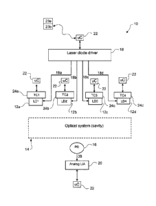
Referring to Figure 1, a scheinatic diagram of a first preferred form gas
detector 10 is
shown. The gas detector 10 is arranged to sense the concentration levels of
four target
gases, namely oxygen, carbon monoxide, methane and hydrogen sulplude. Four
laser
sources 12a-12d are provided that are arranged to transmit radiation at four
target
wavelengths corresponding to the fout target gases through a gas space 14 that
contains a
gas sainple from the sutrounding environment and an optical detector 16 is
provided for
sensing the intensity of the radiation transmitted tlv:ough the gas sample at
each target
wavelength. The gas detector 10 also comprises a control system that operates
and co-
ordinates the laser sources 12a-12d and optical detector 16 and wluch
processes the
detected intensity levels of the radiation emanating from the gas sample to
generate
representative concentration level information in relation to each of the four
target gases
based on the absorption levels. Various methods of calculating concentration
level
information based on absorption levels are known to a skilled person in the
art of laser
spectroscopy. Soine of these calculation techniques will be described below
but it wi11 be
appreciated that other known techniques may also be utilised.
In the first preferred forin, the four laser sources 12a-12d are each arranged
to transmit
infrared radiation at one of tlie target wavelengths corresponding to an
optimum selected
absoiption wavelength of one of the target gases. In particular, each laser
source has a
different wavelength specific to the gas it is targeting. By way of exainple,
Table 1 below
summarises which laser source 12a-12d relates to which target gas and the
associated
approximate transmission wavelength, by way of example only. The target.
wavelengths
may be set at the maximum absorption wavelengths for the target gases,
although other
wavelengths may be more suitable. Various factors are taken into account when
deter.tnining the target wavelengths, including the likely concentration
levels, gas absorption
characteristics (for example, line intensity), radiation path length, system
noise, interference
from other gases, and other such factors. The selected target wavelengths are
a
compromise between these things.
Laser Source Target Gas Target Radiation Wavelength Range, and
Preferable Wavelengths
12a Oxygen 760nm-766nm, preferably 764nm
12b Carbon Monoxide 1560nm-1600nm, preferably 1565nm
12
CA 02674528 2009-06-22
WO 2008/079032 PCT/NZ2007/000391
12c Methane 1630nm-1670nm, preferably 1665nm
12d Hydrogen Sulphide 1560nm-1600nin, preferably 1576nm
Table 1
In the first preferred form, the laser sources 12a-12d are laser diodes, such
as vertical-cavity
surface-emitting lasers (VCSELs) or distributed feedback lasers (DFBs), and
the optical
detector 16 is a suitable photodiode for sensing radiation transmitted for the
particular laser
diode.
Upon exiting the gas space 14, the radiation from laser diodes 12a-12d is
detected by an
optical detector, such as a photodiode 16. In operation, the control system of
the gas
detector 10 is arranged to measute a harmonic of the photodiode 16 output and
from this
extract the absorption level` for each of the target wavelengths transmitted
by the laser
diodes 12a-12d. This measured absorption level of the gas sample at each
wavelength is
proportional to the concentiation levels of the target gases in the gas
sarnple. Therefore,
the ineasured harmonic of the intensity, at each target wavelength, can be
processed to
generate corresponding target gas concentration levels in a inanner well known
to those
skilled in the art of laser spectroscopy. Broadly speaking there are two
methods for
calculating the concentration. The first one uses a sample of the gas of
interest with known
characteristics to calibrate the measureinent device (gas detector): The
second method is
based on knowledge of: the gas's absoiption properties, path length, pressure,
and
temperature. It uses either the signal peak height or a line shape fit of the
signal to extract
the required values for the concentration calculation.
In the fust preferred form, the control system of the gas detector coinprises
a number of
modules or subsystems. In particular, the control system comprises a main
contioller 22,
for exainple a programinable microcontroller or microprocessor, current driver
18, lock-in
amplifier 20, and temperature control modules 24a-24d. The control system may
also
comprise a liquid crystal display (LCD) or other output display, user
interface, teinperature
sensor, pressure sensor, lower explosive litn.it (LEL) sensor, therinistor,
multitone audible
alarin, vibration alarin module, and photodiode signal processing circuits. In
the fitst
preferred form, the main controller 22 interfaces with and conti:ols the
current driver 18
associated with the laser diodes 12a-12d and the lock-in amplifier 20
associated with the
13
CA 02674528 2009-06-22
WO 2008/079032 PCT/NZ2007/000391
photodiode 16. The main controller 22 of the control system also interfaces
and controls
the temperature control inodules 24a-24d associated witlz each of the laser
diodes 12a-12d.
Main controller controls and coordinates all the subsystei.ns. This includes
controlling the
generation of modulation signals, time management and signal processing.
In operation, the main controller 22 of the control system is arranged to
receive and
process the radiation intensity signals sensed by - the photodiode 16,
preferably after
amplification and filtering by the lock-in ainplif er 20, to generate
representative
concentration level information for each of the target gases. In particular,
main controller
22 is arranged to analyse a particular harmonic intensity signal at each of
the four target
wavelengths and then generates representative concentration level information
for each
target gas based on the harmonic signal at each respective target wavelength
in a manner
that has been previously described.
The control system may also comprise 'a user interface 23a and output display
23b
associated with the main controller 22. In particular, the output display may
be arranged to
display the representative concentration levels, for example in ppm levels,
for each of the
target gases on a display screen, such as a liquid crystal display (LCD),
electronic ink, LED
based display or the like. Additionally, the main controller 22 of the control
system may be
arranged to compare the representative concentration levels with preset
maximum or
min~tnum thresholds, tilne weighted averages (TWA), and short time exposure
limits
(STEL) associated with each of the target gases and activate an audible alarin
via a buzzer
and/or a visual alarm via the display and/or a tactile alarm via a vibration
module for the
user should the levels of any of the target gases breach those thresholds. TWA
is time
weighted average and is the recoinmended limit a person can be exposed to a
particular gas
over a period of time without causing harm. There are usually two tirne
periods: 8 hour
exposure and a 15 ininute short term exposure litnit (STEL).
For exainple, the main controller 22 may be preset with predetermined
maxiinuin
threshold, TWA, and STEL concentration levels for hazardous gases carbon
monoxide,
methane, and hydrogen sulphide. Likewise, the main controller 22 may be
provided with a
preset maximum threshold concentration level for oxygen for alerting the user
to an
explosive risk and additionally, a mir,imum preset threshold concentration
level for oxygen
14
CA 02674528 2009-06-22
WO 2008/079032 PCT/NZ2007/000391
to ensure the user can breathe safely within the environment. The control
system inay also
have associated internal or external memory, such as flash mernoiy or any
other type of
non-volatile memoiy, for storing data and input/output ports, for example a
universal
serial bus (USB) for transferring data in relation to the concentration level
information for
the target gases. Additionally, the gas detector 10 may also incorporate
temperature and
pressure sensors for sensing temperature and pressure within the environment
for
displaying to the user. The sensed temperature and pressure levels may also be
utilised by
the main controller 22 during the gas concentration level calculations to
reduceeerrors and
enhance accuracy. Further, the gas detector may also comprise a lower
explosive level
(LEL) sensor or sensors to provide an indication as to whether explosions are
likely within
the environment due to paxticular vapour levels or concentrations. As
mentioned, the gas
detector 10 is preferably portable and hand-held and will comprise power
supply circuitry, a
rechargeable battery and battery charging circuitry.
In the fitst preferred form, the laser diodes 12a-12d are sequ.entially
operated in a cycle to
transmit radiation one at a time by a single current driver 18 of the conttol
system. Further,
the control system includes a lock-in amplifier 20 that amplifies and filters
the intensity
output signal from the photodiode 16, with the lock-in ainplifier parameters
determined by
the laser diode that is operating. In particular, the current driver 18 pulses
each laser diode
12a-12d on and then off in a sequential .tnanner one at a time in a
predetermined pattern
and then repeats the sequential cycle. In a synchronous inanner, the lock-in
amplifier 20 is.,
arranged to sequentially filter and amplify the intensity output signals from
the photodiode
16 for the target wavelength corresponding to whichever laser 12a-12d is
operating for
final processing by the main controller 22 of the control systein. In the
first preferred form,
the currentdriver 18 and lock-in amplifier 20 are controlled and operated by
the main
controller 22 of the control system.
It will be appreciated that the laser diodes 12a-12d maybe operated in any
predetermined
pattern. For example, each laser diode 12a-12d may be operated one at a time
in a
sequence from left to right or specific laser diodes for particular target
gases znay be
operated in a particular preset order. It will also be appreciated that each
cycle of the
pattern may also include skipping operation of one or more of the laser diodes
for
particular target gases. For example, the laser diodes 12b-12d for detecting
target gases
CA 02674528 2009-06-22
WO 2008/079032 PCT/NZ2007/000391
carbon monoxide, methane and hydrogen sulphide may be operated in a
predeterm.ined
order eveiy cycle but Iaser diode 12a for detecting oxygen may only be
operated every tenth
cycle. The reason for this is that the concentration level of oxygen in most
environments is
likely to be inore stable relative to the other gases and therefore its
detection every cycle
inay not be necessaiy.
Referring to Figure 2, an expanded scheznatic diagram of the fu:st preferred
form single
current driver 18 of the gas detector 10 is shown. As mentioned, the gas
detector 10
preferably implements a pulsed current d.tiving scheme to sequentially operate
each of the
laser diodes 12a-12d one at a time in a repeating cycle. Therefore, at any
time only one of
the laser diodes 12a-12d will be switched on and transmitting, the others will
be running at
low power or off and will not be transrnitting. Such a scheine saves power for
the portable
hand-held gas detector 10 compared to continuous operation of the laser
diodes. As
mentioned, the main controller 22 is afranged to control the current ddver 18
to pulse each
laser diode 12a-12d on via pulsed current drive signals 18a-18d. Each current
drive signal
18a-18d comprises a coinbination of a sine wave, triangle (or alternatively
sawtooth) wave,
and DC offset, each of which may be varied according to the target wavelength
of the
radiation to be generated by the particular laser diode 12a-12d being
activated. For each
current drive signal 18a-18d, the particular sine and triangle waves are
generated by sine
wave and triangle wave modules 26 and 28 respectively. In the first preferred
form, the
sine and triangle wave 2nodules 26, 28 are performed by direct digital
synthesis (DDS)
chips that are controlled via the serial peripheral interface (SPI) of the
main controller 22
and the mastex clocks of the DDS chips are preferably driven by the pulse
width
modulation (PW1VI) output from the main contioller 22. The DDS chips can be
programmed to generate triangle or sine waves at a particular modulation
frequency, wlv.ch
may be the saine or alternatively different for each laser diode. The DC
offset is provided
directly from the main controller 22 via its digital-to-analogue converter
(DAC) or PWM
output ports. In the fitst preferred form., the same DDS chips are utilised
for generating
sine and triangle waves for all the laser diodes.
The sine wave, triangle wave, and DC offset signals are combined in adder 32,
such as a 3
signal opainp adder, to generate the particular modulated current drive signal
34 for driving
one of the laser diodes 12a-12d via the output ports 18a-18d of a
demultiplexer 36 that
16
CA 02674528 2009-06-22
WO 2008/079032 PCT/NZ2007/000391
channels the drive signal to the appropriate laser diode 12a-12d on
instruction by the main
controller 22. The resistance of the laser diodes 12a-12d may not be fixed and
therefore a
voltage-to-current converter, such as a transconductance ainplifier, may be
utilised on the
output of the current driver 18. Further, preferably a zener diode clamp is
utilised to ljniit
the output voltage of the adder 32. Iri the fix-st preferred form, a 3.3 volt
zener diode is
utilised or alternatively a 3.3 volt rail-to-rail opamp or any other suitable
voltage limiting
device could be used.
In summary; the main contioller 22 controls the current driver 18 to drive the
laser diodes
12a-12d in a sequential, predeterinined pattern, under the pulsed current
driving scheme
and co-ordinates the generation of the appropriate cuirent drive signal 18a-
18d
(combi.nation of sine wave, triangle wave, and DC offset) for each of the
laser diodes 12a-
12din turn. 15 By way of example, Figure 3 shows an example of the pulsed
current driving scheme and a
possible predetermined pattern of operation per cycle of current drive signals
18a-18d
generated. In summary, during the on pe.tiod for each .laser diode 12a-12d
during a cycle,
its current drive signal 18a-18d is simultaneously triangularly rainped and
sinusoidally
modulated in order to produce a scanned, wavelength modulated, infrared
radiation output
at the laser diode for detecting and ineasurin.g the concentration of one of
the four target
gases at its respective target 'wavelength. In the first pieferred form, the
radiation
transmitted by the laser diodes is scanned across a small range about each
respective target
wavelength to allow for long term drifts in each laser's centre wavelength. If
no target gas is
present, then there is no signal to reference to. The laser's wavelength may
drift over timme
and if a target gas is present it inay not be detected due to this drift.
Scanning each laser's
wavelength over a small range about its center target wavelength helps to
ensure that the
target wavelength is always present in the laser output and thus minimises the
effect of
drift. The pulse frequency and pattern, and DC level of the pulsed current
driving scheine
are preferably set so as to minitnise any laser diode temperature variation in
the target
wavelengths. Further, appropriate setting of the pulse duty cycle and relative
phase of the
individual pulse drive currents 18a-18d of the laser diodes facilitates
reduced power
consuw.nption. An additional method for nlnimising the effects of temperature
drift is the
implementation of periodic bump testing. The user is requested to expose the
detector to a
17
CA 02674528 2009-06-22
WO 2008/079032 PCT/NZ2007/000391
sainple of the gases of interest that allows the device to locate the signals
and correct for
any drift.
Referring to Figure 4, the lock-in ainplifier 20 is ar.ranged to amplify and
filter the intensity
output signal 38 generated by the photodiode 16 in response to detected
radiation. Firstly,
an amplifying component 40, such as a pre-amp, amplifies the intensity output
signal 38.
The amplified signal 42 is then multiplied with a reference signal 44 at
multiplier46. The
reference signal 44 is generated by a reference signal inodule 48, such as a
DDS chip, that is
controlled by the main controller 22 and is phase locked to the laser's sine
wave
modulation source. As rnentioned, the lock-in amplifier 20 is sequentially
configured in a
synchronous manner according to the activation of the laser diodes. 12a-12d
such that it
obtains the intensity output signal from the photodiode 16 for the target
wavelength being
transmitted by the currently activated laser diode 12a-12d. In particular, the
main
controller 22 controls the reference 'signal inodule 48 to generate a
reference signal 44
associated witli the target wavelength of interest, depending on which laser
diode 12a-12d
is activated. In the fust preferred form, the reference signal 44 wi11 be a
harmonic of the
modulation signal that modulates the radiation transmitted at each target
wavelength. By
way of exainple, the lnodulation signal may be the same for each of the laser
diodes. The
inain controller 22 controls the phase of the reference signal 44 generated by
the reference
signal module 48. In the first preferred forin, the main controller 22 ensures
that the phase
difference between the reference signal 44 and the modulation frequency
component in tlie
photodiode output is zero. Therefore, the main controller 22 controls the
phase and
frequency of the reference signal 44. In the first preferred form, the lock-in
amplifier 20
detection is at twice the modulation frequency and preferably the reference
signal 44 froin
the reference module 48 is filtered, for example, by a band pass filter. The
inultiplied signal
50 output froin the inultiplier 46 is then subjected to low pass filter module
52 which
extracts the DC coinponent. The final intensity output signal 54 is then
processed by the
main cont.roller 22 to generate or deterinine representative concentration
level information
for the target gas based on a harmonic signal of the radiation at the target
wavelength
tlzrough the gas sainple. The main controller may be arranged to process a
nw.nber of
signals and average them before using this average to calculate the gas
concentration level
for each target gas. This can iinprove the signal-to-noise ratio.
18
CA 02674528 2009-06-22
WO 2008/079032 PCT/NZ2007/000391
As mentioned, the laser diodes 12a-12d may, for example, be VCSEL or DFB based
lasers,
and each eznits electromagnetic radiation or -waves at one of the specific
target wavelengths
of the target gases. The wavelength of the radiation einitted by each of the
laser diodes
12a-12d is a function of both teinperature and driving current. This calls for
precision
temperature control to an accuracy of approximately 0.1 C as each of the
laser diodes 12a-
12d has to be maintained at a different temperature according to its target
wavelength.
Therefore, there are preferably four independent temperature control modules
24a-24d,
one associated with each of the laser diodes 12a-12d. At a general level, each
temperatu.te
control module 24a-24d comprises a temperature sensor, such as a temperature
dependent
resistor (thermistor), and a temperature controller or actuator, such as a
thermoelectric
cooler (TEC). In the first preferred form, the main controller 22 interfaces
with the
thermistor and TEC of each tei.nperature contiol module 24a-24d to control the
operating
temperatuie of each laser diode 12a-12d depending on the operating parameters
required
to generate radiation at the respective target wavelengths. The thermistor is
connected to a
series resistor to act a voltage divider. The thern-.tistor is supplied with a
precise bandgap
reference voltage generated by the main controller 22. The TEC needs a series
resistor to
limit current through it.
Referi7ng to Figure 5a, each temperature control module 24a-24d employs closed
loop
feedback, with the TEC controlling the laser diode temperature according to a
desired
temperature reference signal and the therinistor sensing and feeding back a
signal
representing the actual laser diode teinperature. By way of example, the
temperature
control module 24a associated with laser diode 12a will be described,
altliough the general
implementation is similar for each of the temperature control modules 24a-24d.
In operation, a desired temperature signal 56 is provided by main controller
22 representing
the desired operating temperature of laser diode 12a to generate its target
wavelength. The
thermistor 58 senses the temperature of the laser diode 12a and generates a
representative
actual temperature signal 60 which is then compared with the desired
temperatute signal 56'
at error module 62. A series resistor with the thermistor 58 supplied by a
regulated voltage
inay form the teinperature-to-voltage converter for the actual temperature
signal 60. A
temperature difference signal 64 representing the difference between the
actual 60 and
desired 56 temperature signals is then output froixi the error module 62 for
processing by
19
CA 02674528 2009-06-22
WO 2008/079032 PCT/NZ2007/000391
the main controller 22. The main controller 22 is then arranged to control the
TEC 66 via
control signals 68 to manipulate the temperature of the laser diode 12a so as
to minimsse
the temperature difference signal 64 and thereby bring the actual temperature
closer to the
desited temperature. With this closed loop feedback arrangement, the
teinperature control
inodule 24a mai.ntains the laser diode 12a at the desired operating
temperature.
Figure 5b shows one particular arrangement of how-the main controller 22
interfaces with
the thermistor 58 and TEC 66. In particular, the thermistor 58 provides a
representative
actual temperature signal 60 to the analogue-to-digital converter (ADC) port
of main
controller 22. The TEC can heat or cool the, laser diode according to the
direction of TEC
current flow. An H bridge may be utilised for changing the TEC current flow
direction. In
order to vary the current magnitude, the DAC of the main controller 22 is used
to generate
the required voltage. Tllis voltage along with the series resistance and TEC
resistance
generates the required current magnitude. The H-bridge may comprise four
analog
switches which are controlled by the control signal (CS) from the main
controller 22. The
temperature control is a software-based discrete proportional-integral-
derivative (PID)
controller running in the rnain controller 22.
Second preferred form gas detector
Referring to Figure 6, a schematic diagram of a second preferred forin gas
detector 100 is
shown. The second preferred form gas detector 100 is similar in functionality
to that of
the first preferred foirn gas detector 10 although there are differences in
configuration that
will be explained.
The gas detector 100 is arranged to sense the concentration levels of the same
four target
gases, namely oxygen, carbon monoxide, methane and hydrogen sulphide. Like gas
detector 10, four Iaser sources 102a-102d are provided for transmitting
infrared radiation at
four target wavelengths corresponding to the optimum absorption wavelengths of
the four
target gases. The radiation is transmitted through a gas space 104 that
contains a gas
sainple froin the environment surrounding the gas detector 100. In the second
preferred
form, a VCSEL laser 102a is utilised for detecting the oxygen concentration
level and three
DFB lasers 102b-102d are utilised for detecting the concentration levels of
carbon
CA 02674528 2009-06-22
WO 2008/079032 PCT/NZ2007/000391
monoxide, methane and hydrogen sulphide respectively. The radiation
transmitted by
VCSEL laser 102a thxough the gas sample is sensed by optical detector 106. The
radiation
transmitted by the three DFB lasers 102b-102d through the gas space 104 is
sensed by
optical detector 108. The output signals from the optical detectors 106,108
are processed
by optical detector signal processing 'module or systein 110 before being
amplified and
filtered by lock-in amplifier 112. In the second preferred form, the optical
detectors
106,108 are photodiodes and the signal processing module is referred to as a
photodiode
signal processing module 110. By way of example, the optical detector 106 may
be a silicon
(Si) photodiode and the optical detector 108 inay -be a germanium (Ge)
photodiode.
The output signals from the lock--in amplifier 112 are tlien processed by the
main controller
114 to generate representative gas concentration levels based on the radiation
absorption
levels at the target wavelength in a manner previously described witli respect
to the first
preferred forin gas detector 10.
The gas detector 100 cornprises a fitst current driver 116 for driving the
VCSEL laser 102a
and a second current driver 118 is arranged to dt-ive the three DFB lasers
102b-102d. The
first current driver 116 preferably activates the VCSEL 102a continuously. The
second
current driver 118 is arranged to sequentially activate the three DFB lasers
102b-102d one
at a time in a cycle using pulsed di-ive currents. Therefore, at any qne time
only one of the
three DFB laser diodes 102b-102d will be activated to transmit radiation while
the VSCEL
laser diode 102a is preferably activated continuously. It will be appreciated
that the VSCEL
laser diode 102a could alternatively be activated in a pulsed inanner to save
power if
desired.
The gas detector 100 also includes the same inain other subsysteins described
in respect of
the first preferred form gas detector 10. In particular, the gas detector 100
comprises four
individual temperature control modules 120a-120d for actively conttolling the
operating
temperature of the laser diodes 102a-102d. The gas detector 100 also comprises
an output
display, alarm modules, inemory (such as EEPROM or the like), on/off
controller, real-
time clock (RTC), output ports (USB, JTAG, or the like) for transferring data
to computers
or other devices, temperature sensor, pressure sensor, LEL, and power supply
circuitry and
charging circuitty as shown in modules 122,124,126 and 128.
21
CA 02674528 2009-06-22
WO 2008/079032 PCT/NZ2007/000391
Referring to Figure 7, a schematic diagram of the first 116 and second 118
current drivers
for the laser diodes 102a-102d is shown. In the second preferred form, the
first current
drive.r 116 is arranged to continuously activate VCSEL laser 102a while the
second current
driver 118 is arranged to sequentially activate the three DFB lasers 102b-102d
one at a tv.ne
in a predeterinined pattern or order and in a repeating cycle using pulsed
drive currents. As
previously described with respect to the first preferred form gas detector 10,
the drive
currents for the laser diodes 102a-102d comprise a sine wave, triangle wave,
and DC offset
to cause the laser diodes to transmit radiation, at each of the target
wavelengths, that is
sinusoidally modulated at the sine wave frequency and ramped according to the
triangle
wave. The current drive signals are modulated so that small signals can be
extracted from
the background noise using the lock-in arnplifier 112 as will be described
later..
DDS modules 142 and 144 generate the sine waves and triangle waves for tlie
current drive
signals 146a-146d. DDS modules 142,144 are controlled by the main controller
114 and
preferably each of the current drive signals 146a-146d for the laser diodes
102a-102d
comprise the same sine wave and triangle wave modulation frequencies or
components.
The VSCEL and DFB lasers utilise different DC offsets and therefore the main
controller
outputs two= different DC inputs. In particular, the DC offset for the VCSEL
laser 102a is
provided by the inain controller 114 via a low pass filter 148 wlvle the DC
offset signal for
the three DFB lasers 102b-102d is provided by the main controller 114 via low
pass filter.
150. Further, the DC offsets for each of the DFB lasers 102b-102d will likely.
be different
as each laser will have its own requirement for the DC offset to give the
target wavelength
requited.
As the current drive signal level (sine wave, triangle wave and DC magnitude)
is different
for the DFB and VSCEL lasers, the first and second current drivers 116 and 118
comprise
separate adders 152 and 154 respectively, such as three-signal opamp adders,
for adding the
sine wave, triangle wave and DC. offset signals. The output of the adders 152
and 154 are
voltage drive signals and are passed through =bandlitnited inverting
amplifiers 153,155
respectively. Then the signals are converted to current drive signals via
transconductance
amplifiers 156,158,160,162 as the resistance of the laser diodes 102a-102d is
not fixed. The
pulsed driving scheme for sequentially activating DFB lasers 102b-102d is
controlled by the
22
CA 02674528 2009-06-22
WO 2008/079032 PCT/NZ2007/000391
main controller 114 via the demultiplexer 164 in a manner similar to that
described in
respect of the first preferred form gas detector 10.
Referring to Figure 8, the signal processing modules or systein 110 for
processing the
output signals from the optical detectors 106 and 108 is shown. In the second
preferred
form, the optical detector 106 for the VSCEL laser 102a is preferably a
silicon (Si)
photodiode. The optical detector 108 for the DFB laser diodes 102b-102d is
preferably a
Ge.rxnanium (Ge) or Indium Gallium Arsenide (InGaAs) photodiode. The output
signals
from the photodiodes 106,108 generated in response to the sensed radiation
transmitted
through the gas sample are passed through current-to-voltage converters
164,166 and
buffers 168 and 170. The main controller 114 of the control system is arranged
to then
selectively channel the buffered signals from the optical detectors 106,108 to
the lock-in
amplifier 1.14 via multiplexer 172 so that the concentration levels for the
target gases can be
determined one at a time in a predetermined pattern in a iepeating cycle
substantially
similar to that described with respect to the first preferred forin gas
detector 10. Further
processing of the signals is provided after the multiplexer 172. In
particular, the
multiplexed signal is band pass filtered 174 to remove unwanted frequency
coinponents
and then amplified 176 before being mixed in the lock-in ainplifier 112.
Referring to Figure 9, a schematic diagram of the lock-in amplifier 112 of the
gas detector
100 is shown. The lock-in amplifier 112 is arranged to filter the signal from
the
photodiode signal processing system 110. In particular, the lock-in amplifier
112 is
arranged to extract a harmonic of the radiation modulation frequency from the
photodiode
signal for processing to detei7nine the gas concentration levels for the
target gases. The
output signal 178 from the photodiode signal processing system 110 is input
into the
multiplier (mixer) 180 of the lock-in amplifier 112. The multiplier 180 is
preferably a four
quadrant analogue multiplier that inixes the output signal 178 with a phase
locked
sinusoidal reference signal 182 generated by a DDS chip 184 as conts:olled by
the main
controller 114. The reference signal 182 is passed through a bandpass filter
and amplifier
186. The frequency of the reference signal 182 as generated by the DDS chip
184 is the
frequency component that is to be extracted from the photodiode output
sigi.ial, and
preferably is a harinonic of the modulation frequency. In one form, the
reference signal
182 may have' a frequency that is twice (or some other integer multiple) of
the modulation
23
CA 02674528 2009-06-22
WO 2008/079032 PCT/NZ2007/000391
frequency of the sine wave generated within the current drivers 116,118. The
mixed signal
188 is then passed through a low pass filter 190 and a level-shifting and
amplification
inodule 192 before being processed by main controller 114 to determine the gas
concentration level.
Referri.ng to Figure 10, a schematic of one of the temperature conttol modules
120a-120d
of the gas detector 100 is shown along with the micro-controller. The
temperature control
modules 120a-120d operate in the same way as those described with respect to
Figures 5a
and 5b of the first preferred form gas detector 10. In particular, the main
controller 114
implements a discrete PID controller (software) to control the operating
teinperature of
each of the laser diodes 102a-102d in accordance with preset temperature set
points with
closed loop feedback. The discrete PID controller interfaces with thermister
circuits 194
for sensing the actual temperatures of the laser diodes 120a and a TEC circuit
196 for
actively controlling the teinperatures of the laser diodes in accordance with
the desited set
points.
Figure 11 shows a possible configuration of the main controller 114
interfacing with the
other rnain subsystems.
Third preferred form gas detector
Referring to Figure 12, a schematic diagram of a third preferred form gas
detector 200 is
shown. The third preferred form gas detector 200 is sitnilar in functionality
and
configuration to that of the second preferred form gas detector 100 with like
components.
being referenced by like reference numbers. The primaiy difference between the
gas
detectors 100 and 200 is that gas detector 200 uti.lzses four VCSEL laser
diodes 202a-202d
for the laser sources for detecting oxygen, carbon monoxide, methane and
hydrogen
sulphide. The advantage of using VCSEL laser diodes over DFB laser diodes is
that the
operating power requirements of VCSEL laser diodes are less than DFB laser
diodes and
therefore provide power savings.
The VCSEL laser diodes 202a-202d are driven by a single current driver 216
which will
now be described with reference to Figure 13. The current driver 216 is
arranged to
24
CA 02674528 2009-06-22
WO 2008/079032 PCT/NZ2007/000391
generate the current drive signals 246a-246d for the laser diodes 202a-202d.
The current
driver 216 is similar to the configuration of the first current driver 116 of
the second
preferred forin gas detector 100. DDS modules 242,244 generate the sine and
tsiangle
waves respectively for the current drive signals 246a-246d. DDS modules
242,244 are
controlled by the main controller 114'and preferably the current driver
signals 246a-246d
comprise the same sine wave and triangle wave modulation frequencies or
components.
The DC offset for the current dsive signals 246a-246d is provided by the main
controller
114 via a low pass filter 248. The sine wave, triangle wave and DC offset
signals are added
together by adder 252, which may for example be a 3-signal op amp adder or the
like. The
output of the adder 252 is a voltage drive signal that is passed through a
bandl'united
inverting amplifier 253. Following the inverting amplifier 253 is a
demultiplexer 264 which
is controlled by the inain controller 114 to selectively channel the output
signal from the
inverting amplifier 253 to one of the VCSEL laser diodes 202a-202d in a
predetermined
order or pattern that repeats in a manner similar to that described in respect
of the first 10
and second 100 preferred forms of the gas detector. The four outputs of the
deinultiplexer
264 are connected to the inputs of the VCSEL laser diodes 202a-202d via
respective
transconductance amplifiers 256a-256d that are arranged to convert the voltage
drive
signals from the deinultiplexer 264 into current dtive signals 246a-246d.
Optical system configurations
In the preferred forms 10,100,200 of the gas detector described above, the gas
space 14,104
of the gas detector may preferably but not'necessarily contain an optical
system that is
arranged to provide modified radiation transinission paths (and therefore
modified path
lengths) in the gas space for one or more of the laser sources according to
the sensitivity
required for each particular target gas. The radiation emitted at the target
wavelengths for
detecting oxygen and methane may be transmitted along a shorter direct
straight path
through the gas sainple. In contrast, the radiation emitted at the target
wavelengths for
detecting carbon monoxide and hydrogen sulphide is preferably transinitted
along a longer
transmission path, for example a zigzagged path through the gas sa.tnple.
Generally, the
longer transinission paths allow gases having smaller concentrations to be
detected.
Oxygen, in a habitable environment, generally has high concentration levels
and therefore a
ditect shorter transmission path can be utilised. Methane has optical
abso:rption properties
CA 02674528 2009-06-22
WO 2008/079032 PCT/NZ2007/000391
at its optimum target wavelength that allow for a shorter direct transmission
path to be
utilised also.
By way of example, Table 2 below su.mi.naflses the preferred radiation
transinission path
5- length ranges and optimal path lengths for each laser source and its
associated target gas.
Laser Source Target Gas Preferred Radiation Transmission Path,
Length Range, and Optimum Path Length
12a,102a,202a , Oxygen 0.01m = 0.1m, preferably 0.05m
12b,102b,202b Carbon Monoxide 20m - 50m, preferably 30m
12c,102c,202c Methane 0.05m - 0.2m, preferably 0.1m
12d,102d,202d Hydrogen Sulphide 10rn - 35m, preferably 20m
Table 2
In the preferred form, the optical system inay comprise a multi-pass cell for
modifying and
increasing the radiation transmission path lengths through the gas sample for
the laser
sources detecting carbon monoxide and hydrogen sulphide relative to a d'v:ect
path through
the gas space. The multi-pass cell may comprise two opposed reflecting
surfaces, such as
miv:rors, located in the gas space and which are arranged to reflect the
infrared radiation
transinitted from the -laser sources inultiple times back and forth within the
gas space
before exiting the gas space for detection. Various shapes of inirrors can be
utilised,'
including planar mirrors and curved mirrors, such as spherical concave mirrors
and
cylindrical concave mirrors. Various examples of multi-pass cells for the
optical system of
the gas detector will be described below.
Example 1- Planar mirror multi-pass cell
Referring to Figure 14, an example of a multi-pass cell having a pait of
opposed planar
inirrors for increasing the path length of infrared radiation emitted froin
the laser sources
that are detecting carbon monoxide and hydrogen sulphide is shown. The planar
mirror
multi-pass cell exainple will be described with reference to the second 100
and third 200
preferred forms of the gas detector where like numbers reference like
components.
26
CA 02674528 2009-06-22
WO 2008/079032 PCT/NZ2007/000391
Laser diode 102a, 202a is arranged to transmit radiation 130 through the gas
space 104
directly to photodiode 106 for sensing the oxygen concentration level.
Likewise, laser
diode 102c,202c is 'arranged to transinit radiation 132 d.i_tectly through the
gas space 104 to
photodiode 108 for detecting the methane concentration level. In contrast,
laser diodes
102b,202b and 102d,202d for detecting carbon monoxide and hydrogen sulpl-iide
concentratioins levels respectively are arranged to transmit respective
radiation 134 and 136
in a zigzagged path through the gas space 104 via the optical system for
detection by
photodiode 108. The optical system comprises a multi-pass cell having a pair
of parallel
opposed planar reflecting surfaces 138 and 140, such as planar mirrors.
Therefore, the
radiation transmission paths for detecting oxygen and methane are shorter
direct straight
paths and the radiation transmission paths for detecting carbon monoxide and
hydrogen
sulphide are longer zigzagged paths. As mentioned, manipulating the radiation
transmission
paths and path lengths through the gas sample enables the sensitivity to be
altered for each
of the target gases depending on requirements.
Typically, the patli length for each target gas is determined based on the
chosen target
wavelength for the target gas (as this determines the gas absoiption
pa.tanieters), the
required detection limit, and the system noise. Oxygen has a high
concentration level in the
atmosphere and therefore a shorter path length can be utilised. Methane has a
stronger
maximum absorption (line sttength) relative to carbon monoxide and hydrogen
sulphide
and tlzerefore can utilise a shorter path length also. The longer zigzagged
transmission
paths of radiation 134 and 136 for carbon monoxide and hydrogen sulphide are
required to
enhance sensitivity for detecting the small concentration levels likely in the
gas sample and
given the optical absorption characteristics of these gases.
Example Z- Spherical concave mirror multi-pass cell with single aperture
With reference to Figure 15, an arrangement of laser sources 302a-302d (for
example laser
diodes such as VCSEL lasers or DFB lasers) and optical detectors
304a,304c,304b/d (for
example photodiodes) is shown. Laser sources 302a,302c transinit infrared
radiation
306a,306c ditectly to their respective optical detectors 304a,304c for
detecting oxygen and
methane respectively. Laser sources 302b,302d transmit infrared radiation
beai.ns
306b,306d via beam splitter 308 and into an optical systein. The optical
system coinprises
27
CA 02674528 2009-06-22
WO 2008/079032 PCT/NZ2007/000391
a multi-pass cell having a pait of opposed spherical reflecting surfaces, such
as spherical
concave mirrors 310,320, which are arranged to fold the infrared radiation
306b,306d back
and forth between the mirrors multiple times to increase the beam path length
through the
gas sample between the mirrors. The multi-pass cell is in the form of a
Heri7ot cell.
Infrared radiation 306b,306d is transmitted via the beam splitter 308 through
a single
input/output aperture 312 located toward the periphery of the fitst spherical
mirror 310
and then onto the reflecting surface of the second spherical mirror 320. The
infrared
radiation then bounces back and forth between the two mirrors 310,320 until
the radiation
beams exit the multi-pass cell through the input/output apertw:e 312. The
exiting beams
306b,d are reflected by a planar mirror 314 toward the optical detector.
304b/d.
Schematic diagrams 310a and 320a show a front view of the reflecting'surfaces
of the first
310 and second 320 mirrors with the input/output aperture 312 being shown. The
laser
spots 310b/d and 320b/d spaced about the peripheiy of the reflecting surfaces
are
examples of the reflection points on the surfaces after the infrared radiation
has entered the
multi-pass cell th.rough the aperture 312 and is periodically reflected and
refocused by the
mirrors 310,320 before exiting the znulti-pass cell through the input/output
aperture 312.
It will be appreciated that an alternative form of the multi-pass cell may
comprise separate
input and output apertures in the same or opposite mirrors though which the
infrared
radiation fro.tn the laser sources 302b,302d may enter and exit the cell. The
laser spot
patterns 310b/d,320b/d on the reflecting surfaces of the mirrors 310a,320a
will be in the
form of an ellipse. The total path length created by the multi-pass cell can
be
approximated by the number of passes back and forth between the inirrors
310,320
inultiplied by the distance or separation between the mirrors. The maximuin
number of
passes depends on the mirror diameter and the input/output aperture diaineter.
Example 3 - Spherical concave mirror multi-pass cell with two apertures
With reference to Figute 16, a modification to the arrangement of example 2
will be
described. Like nurnbers represent like coinponents. In the modified
arrangeinent shown
in Figure 16, the fitst sphei_-ical concave mirror 310 is provided with two
input/output
apertw:es 312b and 312d through which respective infrared beams 306b and 306d
from
28
CA 02674528 2009-06-22
WO 2008/079032 PCT/NZ2007/000391
respective laser sources 302b and 302d may enter and exit the multi-pass cell.
Schematic
diagrams 310a and 320a show the modified laser spot patterns on the reflecting
surfaces of
the mirrors 310 and 320. As shown, the input/output aperture 312b for the
carbon
monoxide laser beam 306b is located further toward the periphery of the first
mirrof 310
relative to the input/output aperture '312d for the hydrogen sulphide laser
beam 306d.
This results in outer elliptical laser spot patterns 310b,320b for the carbon
monoxide
detecting laser beam and inner elliptical laser spot patterns 310d,320d for
the hydrogen
sulphide detecting laser beam on the reflecting surfaces 310a and 320a. Upon
exiting the
multi-pass cell via the input/output apertures 312b,312d the laser beams
306b,306d are
reflected by respective planar mirrors 316,318 to respective optical detectors
304b,304d.
It will be appreciated that the multi-pass cell may have multiple input/output
apertures or
alternatively separate input and output apertures on the- same or opposite
mirrors in
alternative forms if desired. It will also be appreciated that all of the
laser beams 306a-306d
may be arranged to enter and exit the .inulti-pass cell to modif-y and
increase their radiation
transmission path lengths through the gas sample relative to a ditect
transmission path
through the gas sample. In the example above, two laser beams 306b,306d
propagate
within the multi-pass cell in a non-interfering manner in separate regions of
the reflecting
surfaces 310a,320a and this arrangement can be extrapolated to tbree or four
of the laser
beams if desired.
Example 4 - Cylindrical concave mirror multi-pass cell
With reference to Figures 17a-17c, another possible forin of multi-pass ce11
that iuay be
utilised in the optical system of the gas detector wiU. be described. The
arrangement of
laser sources 302a-302d and optical detectors 304a,304c,304b/d are
substantially the same
as that described in example 2 although there is no reflecting planar mirror
314 for
directing the exiting laser beam 306b,306d from the multi-pass cell toward the
optical
detector 304b/d. In this example, the multi-pass cell comprises two opposed
cylindrical
concave mirrors 410 and 420. In a similar manner to the multi-pass cell
described in
example 2, the laser beams 306b,306d enter the multi-pass cell through an
input/output
aperture located in the center of fitst cylindrical concave iyirror 410 and
are then reflected
back and forth between the first 410 and the second 420 cylindrical concave
mirrors
29
CA 02674528 2009-06-22
WO 2008/079032 PCT/NZ2007/000391
inultiple times before exiting the multi-pass cell through the input/output
aperture 412 for
detection at optical detector 304b/d.
Relative to the spherical concave iziirror multi-pass cell of example 2, the
cylindi.-ical
concave mirror multi-pass cell utilises niore of the reflecting surface area
of the mirrors in
that the laser spot pattern takes up more of the reflecting surface area.
Therefore, the
cylindrical concave mitror multi-pass cell can have a reduced cell volume as
well as miiror
size for a given path length desired. Cylindrical concave inirrors have two
principle axes,
one along their planar direction and one perpendicular to this along the
curved direction.
With reference to Figures 17b and 17c, it will. be appreciated by those
skilled in the art that
the cylinducal concave mirrors 410,420, at an appropriate spacing, may be
rotated relative
to one another to provide the desired laser beam reflection pattern and length
for a re-
entrant multi-pass cell. (a cell having a single input/output aperture). In
Figures 17b and
17c, axes Xl and X2 represent the cuived axes of the respective mirrors 410
and 420, and
axes Y1 and Y2 represent the planar axes of the respective mirrors 410 and
420. In one
form., the second mirror 420 may be rotated by an angle 430 with respect to
the first mirror
410. It will also be appreciated that the two opposed cylindtical concave
reflectin.g surfaces
410 and 420 may be provided in a single cylinder having an internal reflecting
surface if
desired.
Specific multi-pass eell parameter examples
Table 3 below sets out exainple parameters for the spherical concave mirror
multi-pass cell
explained in exaa.nple 2 for two particular desired radiation transniission
path lengths,
namely 20.6m and 30.Ozn. The parameters are as follows:
' Diameter = minimum nvrror diameter in mm,
L = path length for the optical cell,
d = mirror separation,
f = mirror focal lengtli (equal to the radius of cuivature divided by 2),
N = number of passes of the laser beams, and
Hole width = maximum diameter (in mm) of the input/output aperture to prevent
the
beain from exiting the cell early.
CA 02674528 2009-06-22
WO 2008/079032 PCT/NZ2007/000391
Path Length (L) 20.6m 30.Om
Diameter 25m.in 25mm
d 170.58mm 154.76ium
f 90mm 80mm
N 120 192
Hole width 1.4nvn 1.4mm
Table 3
Table 4 below sets out exaiziple parameters for the cylindrical concave mirror
multi-pass
cell explained in example 4 for two particular desired radiation
transmissionpath lengths,
namely 20.8m and 31.0m.
Path Length (L) 20.8m 31.Om
Diameter 40inm 40mm
d 138.48mm 156.15mm
f . 120mm 140mm
N 150 198
Hole width 2.5:mm 2.5mm
Table 4
Laser sources, optical detectors and drivers
It will be appreciated that alternative arrangements of laser sources and
optical detectors
may be used in other forms'of the gas detector. The types of laser sources
used, for
example DFBs or VCSELs, can be the same or can be mixtures of different types.
In one
alternative forin, the gas detector may einploy four laser diode and
photodiode aligned
pairs, each pait corresponding to a target wavelength of one of the target
gases. In
another alternative form, the gas detector inay employ a single laser diode
that is
sequentially tunable to each of the four target wavelengths and a
corresponding single
photodiode. Further, it will be appreciated that multiple current drivers may
be utilised to
31
CA 02674528 2009-06-22
WO 2008/079032 PCT/NZ2007/000391
drive multiple laser sotuces in alternative forins of the gas detector. For
ezample, each
laser source inay have its own current driver or alternatively there inay be
t~vo or more
current drivers that are each arranged to drive two or more lasers sources.
Also, multiple
lock-in amplifiers may be provided if multiple optical detectors are used.Each
laser may be
controlled by individual temperature control signals or individual
inicrocontrollers.
Further, it will be appreciated that the four lasers may be run continuously,
rather than in a
pulsed manner. To enable the different radiation signals to be identified at
the detection
end for processing, each laser may be modulated at different modulation
frequencies. A
single photodiode, having a broad wavelength detection range, may then be
utilised at the
detection end and the individual modulation frequencies may be used to
"identify" the
signals for gas concentration determination.
The foregoing desci-iption of the invention includes preferred forins thereof.
Modifcations
inay be made thereto without departing from the scope of the invention as
defined by the
accompanying claims.
32