Note: Descriptions are shown in the official language in which they were submitted.
CA 02674699 2009-07-30
ROCK DRILL TESTING APPARATUS AND METHOD
FIELD OF THE INVENTION
The present invention relates generally to equipment and methods for
testing of rock drills before each deployment for use to determine whether
they are
in good functional condition or in need of service or repair.
BACKGROUND OF THE INVENTION
Stoper and jack-leg drills are two types of rock drills commonly used in
mining operations. These pieces of equipment are deployed to different areas
of a
mine site as their use is required. As with all equipment, it is desirable to
minimize
down time in which the rock drill is not available for use. In mining, a
particular rock
drill will sometimes be deployed from an area at which it is normally stored
to a
particular location in the mine or use by an operator, only for the operator
to discover
that the rock drill is not functioning properly. Time is wasted as the
defective unit
must be transported back out of the mine for repair and a replacement rock
drill is
deployed in its place.
Accordingly there is a desire for rock drill testing equipment and
methods that facilitate testing of rock drills before their deployment into a
mine in
order to first establish that the equipment is in good working order, and not
in urgent
need of service or repair.
SUMMARY OF THE INVENTION
According to a first aspect of the invention there is provided a rock drill
testing apparatus comprising:
a base structure;
CA 02674699 2009-07-30
2
a displaceable structure spaced from the base structure and movable
toward and away from the base structure along a linear axis;
a fluid pumping mechanism mounted to a respective one of the base
and displaceable structures, the fluid pumping mechanism thereof being
operable by
driven rotation of an input shaft thereof extending parallel to the linear
axis, the input
shaft being rotatable about the linear axis relative to the base and
displaceable
structures and being engagable by a drill component of a rock drill at an end
of the
input shaft nearest an opposite one of the base and displacement structures;
a fluid passage communicating with an outlet of the pumping
mechanism;
a flow control mechanism operably installed on the fluid passage at a
distance therealong from the outlet of the fluid pumping mechanism to close
and
then open the fluid passage with the fluid pumping mechanism running to first
cause
a buildup of pressure in the fluid passage when closed and then relieve the
buildup
of pressure in the fluid passage when opened; and
an indicator mechanism associated with the fluid passage and
operable to provide an indication of a status of the buildup of pressure in
the flow
passage under operation of the fluid pumping mechanism with the fluid passage
closed.
Preferably the fluid pumping mechanism comprises a hydraulic pump
and the fluid passage is also communicating with an inlet of the fluid pumping
mechanism.
CA 02674699 2009-07-30
3
Preferably the fluid passage comprises a fluid conduit that
communicates with the inlet and outlet of the fluid pumping mechanism and a
hydraulic fluid reservoir connected inline with the fluid conduit at a
position
therealong between the flow control mechanism and the inlet of the fluid
pumping
mechanism.
Preferably the hydraulic fluid reservoir is mounted on the respective
one of the base and displaceable structures on which the hydraulic pump is
mounted.
Preferably the flow control mechanism comprises a pressure relief
valve installed on the fluid passage to open the fluid passage only after the
pressure
buildup therein exceeds a given level.
Preferably there are provided displacement resisting devices
associated with the displaceable structure to resist movement thereof away
from the
base structure. Preferably the displacement resisting devices are configurable
to
allow adjustment of resistance to movement of the displaceable structure away
from
the base structure.
Preferably the displaceable structure disposed over the base structure
and is movable upward and downward away from and toward the base structure.
Preferably the displacement resisting devices comprises weights
carried with the displaceable structure and suspended at a position downward
therefrom. Preferably the weights are selectively disconnectable from the
displaceable structure to facilitate swapping of different weights for one
another on
the apparatus.
CA 02674699 2009-07-30
4
Preferably the weights have guide features thereon cooperable with
stationary guide members projecting away from the base structure toward the
displaceable structure to guide motion of the weights along the guide members
during lifting and lowering of the displaceable structure away from and toward
the
base structure.
Preferably the guide features comprise collars fixed to the weights and
closing around the guide members.
Preferably there are provided stops defined on the guide members for
engagement thereagainst by the guide features on the weights under lifting of
the
displaceable structure away from the base structure by a given distance to
prevent
movement of the guide features passed upper ends of the guide members.
Preferably the weights comprise metal plates.
Preferably the guide members comprise outer tubular members fixed
to the base structure and projecting upward therefrom parallel to the linear
axis and
inner members fixed to and projecting downward from the displaceable structure
are
slidably received in the guide members to limit movement of the displaceable
structure to movement along the linear axis.
Preferably the indicator mechanism comprises a pressure gauge
operably installed on the fluid passage between the outlet of the fluid
pumping
mechanism and the flow control mechanism.
Preferably the fluid pumping mechanism is carried on the displaceable
structure on a side thereof opposite the base structure and the input shaft
projects
through the displaceable structure.
CA 02674699 2009-07-30
Preferably movement of the displaceable structure is guided by a pair
of parallel telescopic supports projecting from the base structure to the
movable
structure, the telescopic supports comprising stationary sections fixed to the
base
structure adjacent opposite sides thereof and movable sections slidable
relative to
5 the stationary sections toward and away from the base structure, and the
displaceable structure comprising a cross member fixed to and extending
between
the movable sections of the parallel telescopic supports for movement with the
movable sections toward and away from the base structure.
Preferably the stationary sections of the telescopic supports comprise
tubular members in which the movable sections of the telescopic supports are
slidably disposed.
Preferably the pumping mechanism is mounted to the displaceable
structure.
According to a second aspect of the invention there is provided a rock
drill testing apparatus comprising:
a base structure;
a displaceable structure positioned over the base structure at a
distance upward therefrom and lowerable and liftable toward and away from the
base structure along a linear axis;
a rotatable element mounted to a respective one of the base and
displaceable structures and extending parallel to the linear axis, the
rotatable
element being rotatable about the linear axis relative to the base and
displaceable
structures against a source of rotation resistance and being engagable by a
drill
CA 02674699 2009-07-30
6
component of a rock drill at an end of the rotatable element nearest an
opposite one
of the base and displacement structures; and
weights carried with the displaceable structure and suspended at
positions downward therefrom to resist lifting of the displaceable structure
away from
the base structure.
According to a third aspect of the invention there is provided a rock drill
testing method comprising:
positioning a rock drill between a base surface and a displaceable load
movable toward and away from the base surface;
with the rock drill remaining between the base surface and
thedisplaceable load, performing a leg test and a drill test, the leg test
comprising
attempting to extend a telescopic leg component of the rock drill against the
load to
move the load away from the base surface and the drill test comprising using a
drill
component of the rock drill as a drive source for a fluid pumping mechanism to
attempt to pump fluid into a closed fluid passage and buildup a pressure level
therein; and
deeming the rock drill either (a) suitable for use if the rock drill passes
both the leg test and the drill test by successfully moving the load away from
the
base surface in the leg test and successfully building up the pressure level
in the drill
test, or (b) unsuitable for use if the rock drill fails one or both of the leg
test and the
drill test.
CA 02674699 2009-07-30
7
BRIEF DESCRIPTION OF THE DRAWINGS
In the accompanying drawings, which illustrate an exemplary
embodiment of the present invention:
Figure 1 is a front elevational view of a rock drill test apparatus
according to the present invention.
Figure 2 is a side elevational view of the rock drill test apparatus.
Figure 3 is a front elevational view of a hanger bracket of the rock drill
test apparatus.
Figure 4 is a side elevational view of a weight of the rock drill test
apparatus.
Figures 5A and 5B are overhead plan and front elevational view of a
hydraulic pump mounting bracket of the rock drill test apparatus.
Figures 6A and 6B are overhead plan and front elevational views of a
hydraulic pump mounting spacer of the rock drill test apparatus.
Figure 7 is a front elevational view of a hydraulic reservoir mounting
bracket of the rock drill test apparatus.
Figure 8 is a side elevational view of a pressure relief valve mounting
bracket of the rock drill test apparatus.
Figures 9A and 9B are side elevational and overhead plan views of a
weight guiding bracket of the rock drill test apparatus
DETAILED DESCRIPTION
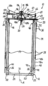
Figures 1 and 2 show an apparatus 10 for testing both the
pneumatically expanding and contracting leg component and pneumatically
rotating
CA 02674699 2009-07-30
8
drill component of a rock drill, whether a stopper drill or jack-leg drill.
The testing
apparatus 10 of the illustrated embodiment is configured as an upright stand
having
a horizontally oriented base frame 12, a pair of parallel telescopic support
leg
assemblies 14 projecting vertically upward from the base at opposite sides
thereof
and a horizontally oriented cross member 16 extending between the support leg
assemblies 14 at the movable upper ends thereof opposite the base frame 12. A
hydraulic pump 18 is mounted atop the cross member 16 and has its internal
drive
shaft coupled with a rod 20 that projects vertically downward through the
cross
member 16 at a central position between the support leg assemblies 14 to form
an
extension of the pump drive shaft so that the rod and driveshaft are rotatable
together and collectively form an input shaft assembly that is rotatable to
drive the
pump. For testing of a rock drill, the bottom base end of the rock drill's air
leg is
placed atop the base frame 12 of the test apparatus 10, or the ground
therebeneath,
and the chuck of the rock drill's drilling end is locked onto the rod 20.
Expansion of
the air leg with the rock drill in this vertically position in the test stand
acts to lift the
weight of the cross member 16 and the components carried therewith to verify
the
functionality of the air leg, and driving of the drill component of the rock
drill drives
the hydraulic pump to build up a pressure in a hydraulic conduit connected to
the
pump to confirm the rotational functionality of the rock drill.
Structure
The structure of the illustrated testing apparatus 10 is described in
further detail as follows.
CA 02674699 2009-07-30
9
The base frame 12 features a pair of feet 22 each disposed
immediately beneath a respective one of the telescopic leg assemblies 14 and
each
formed by a length of rectangular steel tubing extending horizontally in a
direction
normal to the vertical plane at which the two parallel support legs 14 lie. A
central
member 24 of the base frame 12 extends horizontally between the two feet 22 at
the
plane of the support legs 14, closing off a planar rectangular area bound
between
the two support legs 14 the cross member 16 and the central frame member 24.
Each support leg assembly 14 features a stationary section 26 defined by
another
length of rectangular steel tubing fixed at its lower end to the respective
foot 22 at a
central position therealong to project vertically upward from the horizontal
base
frame 12. The upper end of the stationary tube 26 is left open and a
respective
cross-sectionally smaller piece of steel rectangular tubing fixed at its upper
end to
the cross member depends downward into the stationary tube 26 through the open
upper end thereof to define a movable section 28 of the respective leg
assembly 14
slidably disposed within the stationary section to give the leg assembly a
telescopic
configuration. Triangular vertically oriented gusset plates 55 are fixed
between the
central frame member 24 and the stationary sections 26 to better support the
leg
assemblies 14.
The telescopically assembled linear sections 26, 28 of the leg
assemblies 14 allow the cross member 16 to move relative to the base frame 12,
but
substantially limit this motion of the cross member 16 to vertical
displacement along
a linear vertical axis A normal to the horizontal plane of the base frame 12.
The
displaceable cross bar 16 of the illustrated embodiment is defined by a piece
of
CA 02674699 2009-07-30
rectangular steel tubing of the same dimension as that of the movable inner
sections
28 of the leg assemblies 14, this cross bar being fixed to and crossing the
upper
ends of the inner leg sections 28 so as to extend laterally outward past the
two leg
assemblies on opposite sides of the base frame 12. At these shoulder-like end
5 portions 16a of the cross member 16 projecting outward past the respective
leg
assemblies 14, hanger brackets 30 are fixed to and project a short distance
downward from the bottom surface of the cross member 16. In the illustrated
embodiment, each of the two hanger brackets is defined by a small metal plate
30a
fixed to the cross member 16 at an upper end, for example by welding, and
having a
10 single round hole 30b passing normally therethrough near a bottom end of
plate
furthest from the cross member 16, as shown in Figure 3. A shackle 32 passes
through the hole of each hanger bracket 30 and a vertically hanging steel
cable 34
passes through the opening of the shackle 32 and then folds back over itself
to
define an upper end of the cable connected to the shackle and hanger bracket,
the
cable being secured to itself by cable clamps 36 to define this looped upper
end. A
likewise looped bottom end of the cable formed by another portion of the cable
where it is folded back over itself and secured by additional cable clamps 38
carries
a weight 40. As shown in Figure 4, the weight of the illustrated embodiment is
provided by a generally rectangular steel plate 40a having an integral lug 40b
projecting vertically upward from a top horizontal edge of the otherwise
rectangular
weight. A round hole 40c passing normally through the flat lug 40b has another
shackle 44 passed through it, which in turn has the looped bottom end of the
cable
34 passed through it to form the connection between the cable and the weight
40.
CA 02674699 2009-07-30
11
Each weight 40 is provided with a guide bracket 42 projecting from the
inwardly directed face of the weight facing toward the weight on the opposite
side of
the stand. The guide bracket 42 cooperates with the plate structure of the
weight to
define a rectangular collar that closes about the stationary lower section 26
of the
respective leg assembly adjacent the weight 40. With reference to Figure 9,
the
guide bracket 42 of the illustrated embodiment is a flat bar having been bent
at right
angles at four points along its width to take on a winged U-shape with
straight flat
sections and right angle corners. The resulting guide bracket 42 has two
spaced-
apart coplanar foot sections 42a at opposite ends, two parallel leg sections
42b
projecting at right angles from the adjacent inner ends of the foot sections
42a and a
central section 42c parallel to the foot sections to perpendicularly
interconnect the
leg sections 42b at ends thereof opposite the foot sections. The central and
leg
sections 42b, 42c define a squared-off U-shape, and the foot sections define
wings
of this U. Each foot section 42a has a round through hole 42d passing normally
therethrough to receive a respective one of two threaded studs 40d projecting
normally from the inwardly directed face of the respective weight 40 at
symmetrical
positions horizontally across a central vertical axis 40e of the weight's
plate
structure. The U-shape of the guide bracket 42 has its feet 42a placed against
the
inner face of the weight from the side of the respective leg assembly 14
opposite the
weight to slide the holes 42d of the guide bracket 42 over the studs 40d of
the
weight for tightening of nuts 44 onto the studs from the side of the feet 42a
opposite
the face of the weight to fasten the guide bracket onto the weight. As a
result, the
stationary lower section 26 of the telescopic support leg assembly 14 is
disposed
CA 02674699 2009-07-30
12
within a rectangular area bound by the three sides of U-shaped portion of the
guide
bracket 42 and the inner face of the weight.
Referring to Figure 1, lifting of the cross member 16 away from the
base frame 12 acts to also lift the inner sections 28 of the telescopic
support legs 14
and the weights suspended from the cross member by the hanger brackets 30 and
cables 34. The guide brackets 42 on the weights 40 slide along the stationary
lower
sections 26 of the support leg assemblies 14 to guide the weights during this
lifting
and subsequent lowering so that the weights follow linear paths parallel to
those of
the displacement of the cross member 16 and inner movable sections 28 of the
support legs 14. The stationary lower sections 26 of the telescopic leg
assemblies
14 thus not only define guides to establish the linear motion path of the
cross
member and attached inner leg sections 28, but also define guides to establish
parallel paths of motion for the weights. A small rectangular plate 46 fixed
to the
stationary lower section 26 of each telescopic leg assembly 14 projects
horizontally
inward therefrom a short distance toward the opposite leg assembly to form a
stop
that limits upward sliding of the guide brackets 42 on the weights to prevent
sliding
of the guide brackets 42, and the bottom ends of the movable inner sections 28
disposed at an elevation below the guide brackets 42, from sliding upwardly
past the
stops and off the top ends of the stationary lower sections 26 of the leg
assemblies
14.
At a central position along the cross member 16, a vertical hole passes
therethrough along the central axis A between the support leg assemblies 14.
Two
flanged roller bearings 48a, 48b are mounted on the cross member, one on the
CA 02674699 2009-07-30
13
upward facing side thereof to define an upper roller bearing 48a and one of
the
downward facing side of the cross member to define a lower roller bearing 48b.
The
central opening through each of these two roller bearings 48, 48b is
concentrically
aligned with the vertical hole through the cross member 16. In the illustrated
embodiment, the two roller bearings are the same and have their flanges bolted
to
the cross member 16 by bolts passing through the flanges of both bearings and
the
cross member therebetween. A thrust bearing 50 is mounted to the lower roller
bearing 48b at a position immediately therebeaneath. The rod 20 is made of
drill
steel and passes vertically upward form its bottom end through the thrust
bearing 50,
lower roller bearing 48b, cross member 16 and upper roller bearing 48a. At its
top
end, the rod 20 is fixed to a mechanical coupling 52 that couples the rod 20
to the
drive shaft of the hydraulic pump 18.
A pump mounting bracket 54 installed on the cross member 16
supports the hydraulic pump 18 at a distance above the cross member 16. The
pump mounting bracket of the illustrated embodiment, shown in isolation in
Figure 5,
is formed by a flat steel bar bent into a shape somewhat similar to that of
the guide
brackets 42, but on a larger scale. The installed pump mounting bracket 54
features
two coplanar horizontal feet 54a disposed on opposite sides of the rotational
rod and
bearing assembly at the center of the cross member 16, a pair of legs 54b
projecting
convergingly upward from adjacent inner ends of the feet 54a nearest the rod
20 and
a central section 54c horizontally interconnecting the top ends of the
converging legs
54b at a position over the connection of the mechanical coupling 52 to the rod
20. A
pair of round steel cylindrical spacers 56, one of which is shown in isolation
in Figure
CA 02674699 2009-07-30
14
6, each feature a bore 56a passing vertically therethrough along the
longitudinal axis
of the spacer's cylindrical shape. Each spacer is disposed between the top
surface
of the cross member 16 and the bottom surface of a respective foot 54a of the
pump
mounting bracket 54. A bolt passes vertically through the cross member 16, the
bore 56a of the spacer 56 and a through hole 54d in the respective foot 54a of
the
pump mounting bracket and is fitted with a mating nut to clamp these elements
together and secure the pump mounting bracket 54 in place atop the cross
member
16. The drive shaft of the pump 18, or part of the mechanical coupling 52
fixed
thereto, passes vertically through a central through hole 54e in the central
section
54c in the pump mounting bracket. Four mounting holes 54f near the four
corners of
the central section 54c of the pump mounting bracket 54 are provided to
receive
fasteners to facilitate mounting of the housing of the pump 18 to the top
surface of
the pump mounting bracket's central section 54c.
A reservoir 58 containing hydraulic fluid is also mounted atop the cross
member 16 using a bracket. The reservoir mounting bracket 60 of the
illustrated
embodiment, shown in isolation in Figure 7, is a flat steel bar bent into
three linearly
extending sections disposed at right angles to one another to create two legs
60a
fixed to the cross member, for example by welding, to project vertically
upward from
the top surface of thereof and a central section 60b extending horizontally
between
the upper ends of these legs. The hydraulic fluid reservoir 58 is fixed atop
the
central section 60b of the reservoir mounting bracket 60 and includes an oil
filler
tube 58a projecting vertically upward from within the reservoir. A first
section of
flexible tubing 62 is connected to the reservoir at one end in sealed fluid
CA 02674699 2009-07-30
communication with the reservoir's interior through a port in a wall of the
reservoir
and is coupled to the pump 18 at the opposite end in sealed fluid
communication
with an inlet 18a of the hydraulic pump 18. A second section of flexible
tubing 64 is
connected in sealed fluid communication with an outlet 18b of the hydraulic
pump at
5 one end and with in an inlet side of a pressure gauge 66 at an opposite end.
A third
section of tubing 67 is connected in sealed fluid communication with an outlet
of the
pressure gauge 66 at one end and with in an inlet side of a pressure relief
valve 68
at an opposite end. A final fourth section of tubing 70 is connected in sealed
fluid
communication with an outlet of the pressure relief valve 68 at one end and
with an
10 inlet port of the reservoir 58 at the opposite end. The tubing sections
thus define a
fluid flow passage that connects the inlet and outlet of the pump and by way
of a
conduit having an inline installation thereon of a pressure gauge, pressure
relief
valve and fluid reservoir, in this order, from the pump outlet to the pump
inlet. In the
illustrated embodiment, the reservoir and pressure relief valve are carried
adjacent
15 opposite ends of the cross member 16 on opposite sides of the centrally
mounted
pump, and the pressure relief valve 68 is mounted on top of the cross member
using
a valve supporting bracket 69, shown in isolation in Figure 8, formed by a
vertically
projecting plate having fastener holes 69a and being fixed to the top surface
of the
cross member 16, for example by welding.
Although not readily visible in the drawings, the test stand apparatus
may have rubber pads of 1/4-inch thickness placed between each foot of the
pump
mounting bracket and the respective spacer, between each spacer and the cross
member and between the pump housing and the central section of the pump
CA 02674699 2009-07-30
.............. ......
16
mounting bracket to provide vibratory isolation between the pump and the cross
member during operation of the pump.
Operation
The use of the illustrated testing apparatus 10 is described in further
detail as follows.
The air leg of a stoper or jack-leg type rock drill is stood vertically
between the parallel support leg assemblies 14 of to engage the base end of
the air
leg with the central frame member 24 or the ground on which the base frame 12
is
disposed. For example, a stoper drill with a pointed tip of its air leg's
piston rod may
engage the central frame member 24 by inserting the pointed tip into a
vertical hole
passing through the central frame member's 24, or at least through the
horizontal
top wall of the tubular structure of the illustrated central frame member 24,
at the
central vertical axis A of the test stand apparatus, as generally indicated at
72 in
Figure 1. The claw-like foot of a jack-leg drill may instead be placed over
the central
frame member 24 to instead seat upon the ground on opposite sides thereof. The
frame assembly or the ground on which it is disposed to support the test stand
apparatus thus forms a stationary horizontal base structure against which air
leg
may push when telescopically expanded under pneumatic actuation.
The stand is built sufficiently tall so that the cross member 16 is high
enough to accommodate the length of the rock drills to be tested between the
base
structure and the bottom end of the rod 20 when the cross member is in its
lowest
position, which may correspond to the movable sections 28 of the support legs
14
CA 02674699 2009-07-30
17
sitting atop the feet 22 of the base frame 12, the cross member 16 sitting
atop the
top ends of the stationary sections 26 of the support legs 14, or engagement
of
some other stop-defining configuration denoting the fully retracted position
in which
the cross member is nearest the base structure. The drill chuck of the rock
drill is
opened, the air-leg is telescoped to expand a short distance to position the
rod 20
within the drill chuck, and the chuck is subsequently closed around the rod 20
of the
test stand for gripping thereof in the same manner as it would engage a rock
drill bit
when prepared for use of the drill at a mining site. With the air leg and
drill
component of the rock drill coupled to a suitable source of compressed air in
its
normal manner, the rock drill is now considered installed in the test stand
apparatus
and ready for testing.
The stand enables testing of both the air leg and the drill component of
the rock drill simultaneously, or separately but without requiring any removal
of the
rock drill or reconfiguration of any aspect of the rock drill's installation
within the test
stand.
In a leg test or lift test, the air leg control is used to introduce
compressed air to force the expansion of the air leg and accordingly displace
the drill
component at the top of the air leg upward, this acts to lift the cross member
16 and
all components of the apparatus mounted thereon and carried therewith. The
mass
of the weights 40 supported from the cross member 16 are selected so that the
overall mass of the cross member and components carried therewith is low
enough
so that the drills being tested should be able lift this mass through
operation of the
air leg pneumatic controls in the expansion driving manner when the drill is
in good
CA 02674699 2009-07-30
18
operating condition, but sufficiently high so that a rock drill air leg not in
such good
operation condition, but rather being in need of service or repair would not
lift the
cross member and components carried therewith. Using a shackle at one or both
of
the connections between each cable and the cross member and respective weight
allows easy removal and installation of weights on the apparatus to allow
changing
of the lift-resisting weight to enable testing of rock drills with different
air leg
specifications and capabilities.
In a drill test or torque test, the drill component is driven to drive
rotation of the rod 20, which in turn drives operation of the hydraulic pump
18 via the
driveshaft thereof. This draws hydraulic fluid from the reservoir through the
pump,
forcing it onward past the pressure gauge into the normally closed pressure
relief
valve. With this valve mechanism closed, the pumping of fluid from the pump
against this closure of the conduit builds up the pressure within the portion
of the
conduit between the pump and the relief valve. Once this pressure buildup
exceeds
the threshold pressure value of the relief valve, the valve opens to allow the
pressurized fluid to continue onward through the remainder of the conduit back
to
the reservoir 58. An operator of the test apparatus can confirm that the
drill's torque
is driving the pump sufficiently to reach this threshold pressure value in the
closed
section of the conduit by monitoring the pressure gauge. As shown in Figure 2,
the
pressure gauge can be obliquely angled downward for easy viewing by the user
from below. If no pressure buildup and subsequent relief is occurring, then
the drill
is not sufficiently driving the pump. Like with the mass selected to resist
the lifting
action on the test stand by the air leg, the threshold or actuating value of
the relief
CA 02674699 2009-07-30
19
valve is selected on the basis that driving of the pump with a properly
operating drill
will be capable of exceeding the this pressure value in the conduit, but a
drill in need
of repair would not reach the threshold pressure value. Use of an adjustable
pressure relief valve allows this value to be changed to accommodate testing
of rock
drills with different drill specifications and rotational capabilities.
The testing apparatus can be calibrated once by determining the load
lifting and rotational capabilities of a particular type of drill, or of
different drills having
similar capabilities or ratings, and then used repeatedly to test multiple
drills of the
same type or ability. The individual tests require no taking of measurements
and no
comparison of performance values against the known performance characteristics
of
a properly functioning drill of the same type. The operator of the test stand
merely
needs to visually confirm the lifting of the cross member and visually confirm
the
fluctuating pressure in the fluid passage under the opening and subsequent re-
closing of the relief valve. Failure of the rock drill to upwardly displace
the cross
member in the leg test indicates repair of the air leg component of the rock
drill is
likely required, and accordingly the rock drill should not be dispensed for
use in a
mine. In the same manner, failure of the rock drill to build up sufficient
pressure to
actuate the relief valve indicates repair of the drill component of the rock
drill is likely
required, and accordingly the rock drill should not be dispensed for use in a
mine.
Acknowledging failure of one or both of the tests prevents an unsuitable rock
drill
from being sent out for use on the job, and identifying which of the two tests
failed
provides further information on which of the two components requires repair.
Not
only is time not wasted on transporting the rock drill into a mine, only to
realize it is
CA 02674699 2009-07-30
not functional and have to transport it back out of the mine for repair, but
also
diagnostic and/or disassembly and reassembly time during repair is minimized
since
which one(s) of the component require repair has already been identified.
The present invention can therefore be employed at a mining site, for
5 example at a shop or storage area outside the mine, to quickly and easily
test each
rock drill before its deployment into the mine to improve productivity by
reducing
otherwise wasted transport and repair downtime of a rock drill.
Variations
10 The particular materials and part configurations described with
reference to the illustrated embodiment reflect a prototype construction
employed in
development of the present invention, and will be appreciated that material
types,
structure of individual parts and configuration of the parts with one another
may be
varied without departing from the scope of the present invention. For example,
while
15 mild steel plates and bars and steel tubing were used in the prototype,
other
materials may be employed, for example to reduce the weight of the apparatus
to
increase portability, provided that the resulting parts are of suitable
strength for the
end use of the apparatus. Telescopic rail assemblies, as opposed to nesting of
a
tube or bar within a larger outer tube, may be employed for sliding lifting
and
20 lowering of the cross member. It also may be possible to replace the
telescopically
supported cross member with a displacable structure that slides or rolls along
vertical rails projecting away from the base and has its fully retracted
position
nearest the base defined by stops in the rails at a distance above the base.
CA 02674699 2009-07-30
...........
21
In a further alternate embodiment, the testing apparatus may be laid
out horizontally instead of being configured as the vertically extending test
stand of
the illustrated embodiment. A fixed body structure defining a vertical base
surface
against which the air leg can push could have a horizontally displaceable
structure
spaced therefrom, the rock drill being being placeable between the structures
to
bear against the fixed structure and displace the movable structure away
therefrom
under expansion of the leg. Telescopic or rail supports could again guide or
limit the
motion of the displaceable structure to occur in a linear manner. However, the
vertical stand construction has the benefit that the weight of the
displaceable
structure and components carried therewith acts to automatically return it to
the
retracted position, and also benefits from a smaller footprint (i.e. less
occupied
surface area / floor space). It will also be appreciated that the pump used to
test the
torque or rotational performance of the rock drill, and the associated
components
cooperating the pump, may alternatively be mounted on the stationary base, as
opposed to the displaceable structure movable relative thereto.
The suspended weights of the illustrated embodiment improve safety
by keeping a significant portion of the lift-resisting weight lower than if
carried directly
on the cross member, making the apparatus less top-heavy, and the weight
guides
prevent the weights from swinging or swaying and potentially injuring the
operator or
other personnel. However, other test systems or methods in which weights are
not
suspended below the cross member, including horizontally oriented test
apparatuses
mentioned above, could still make use of the easy to evaluate torque test
using the
pumping and pressurization of a fluid as the performance marker. Similarly,
CA 02674699 2009-07-30
22
vertically oriented stands using the suspended weights may benefit from their
advantages without necessarily using a fluid-based torque test if some other
source
of rotational resistance is instead employed to allow visual confirmation of a
rock
drill's rotational performance when the rotational resistance is overcome. In
the
illustrated embodiment, the lifting resistance is adjustable by adding to or
reducing
the weight carried by the cross member and attached movable sections of the
support legs and the rotational resistance is adjustable by changing the
threshold
pressure value of the relief valve benefits from flexibility and adaptability,
but test
systems intended for use with only one particular rock drill type may be
constructed
to have fixed resistances based on the known performance characteristics of a
properly functioning drill of that type.
While the illustrated embodiment uses a pressure gauge to reflect
whether the rotational drive of the drill is in good operating condition based
on the
pressure in the fluid passage, it may be possible to use other indicators. For
example, it may be possible to configure the relief valve to perform some
function
upon reaching the threshold pressure that provides an indication of a
successful
torque test to the operator. While this could trigger an audible signal,
preferably a
visual signal or indicator is used due to high noise levels associated with
the
operation of a rock drill.
It will also be appreciated that the fluid being pressurized through the
rotation of the rock drill need not necessarily be a hydraulic fluid or even a
liquid, as
an alternative embodiment could alternatively pressurize and subsequently
release a
gas or combination of gases. For example, one embodiment could use coupling of
CA 02674699 2009-07-30
23
the rock drill chuck to the driveshaft of an air compressor discharging into a
closed
conduit or vessel until the pressure buildup exceeds the actuating value of a
pressure relief valve installed thereon. The air compressor could draw on
ambient
air from the environment in which the apparatus is installed and bleed the
pressurized air off back into the environment through a suitable discharge
after the
pressure relief valve is opened.
Since various modifications can be made in my invention as herein
above described, and many apparently widely different embodiments of same made
within the spirit and scope of the claims without department from such spirit
and
scope, it is intended that all matter contained in the accompanying
specification shall
be interpreted as illustrative only and not in a limiting sense.