Note: Descriptions are shown in the official language in which they were submitted.
CA 02674820 2013-01-04
WO 2008/086196
PCT/US2008/050260
SYSTEMS AND METHODS FOR
SELECTIVELY IMAGING OBJECTS IN A DISPLAY
OF MULTIPLE THREE-DIMENSIONAL DATA-OBJECTS
FIELD OF THE INVENTION
[003] The present invention generally relates to systems and methods for
selectively
imaging objects in a display of multiple three-dimensional data-objects, which
include
objects of interest such as, for example, horizons, reservoir grids and well
paths.
BACKGROUND OF THE INVENTION
[004] In some fields, it is useful to model objects in two or three
dimensions.
Modeling such objects proves useful in a variety of applications. For example,
modeling the subsurface structure of a portion of the earth's crust is useful
for finding
oil deposits, locating fault lines and in other geological applications.
Similarly,
modeling human body parts is useful for medical training exercises, diagnoses,
performing remote surgery or for other medical applications. The foregoing
objects
are exemplary only, and other fields may likewise find utility in modeling
objects.
[005] In the field of earth sciences, seismic sounding is used for
exploring the
subterranean geology of an earth formation. An underground explosion excites
1
CA 02674820 2009-07-03
WO 2008/086196
PCT/US2008/050260
seismic waves, similar to low-frequency sound waves that travel below the
surface of
the earth and are detected by seismographs. The seismographs record the time
of
arrival of seismic waves, both direct and reflected. Knowing the time and
place of the
explosion, the time of travel of the waves through the interior can be
calculated and
used to measure the velocity of the waves in the interior. A similar technique
can be
used for offshore oil and gas exploration. In offshore exploration, a ship
tows a sound
source and underwater hydrophones. Low frequency, (e.g., 50 Hz) sound waves
are
generated by, for example, a pneumatic device that works like a balloon burst.
The
sounds bounce off rock layers below the sea floor and are picked up by the
hydrophones. In either application, subsurface sedimentary structures that
trap oil,
such as faults and domes are mapped by the reflective waves.
[006] In the medical field, a computerized axial topography (CAT) scanner
or
magnetic resonance imaging (MRI) device is used to collect information from
inside
some specific area of a person's body. Such modeling can be used to explore
various
attributes within an area of interest (for example, pressure or temperature).
[007] The data is collected and processed to produce three-dimensional
volume data
sets. A three-dimensional volume data set, for example, may be made up of
"voxels"
or volume elements, whereby each voxel may be identified by the x, y, z
coordinates
of one of its eight corners or its center. Each voxel also represents a
numeric data
value (attribute) associated with some measured or calculated physical
property at a
particular location. Examples of geological data values include amplitude,
phase,
frequency, and semblance. Different data values are stored in different three-
dimensional volume data sets, wherein each three-dimensional volume data set
represents a different data value.
2
CA 02674820 2013-01-04
WO 2008/086196
PCT/US2008/050260
[008] Graphical displays allow for the visualization of vast amounts of
data, such as
three-dimensional volume data sets, in a graphical representation. However,
displays
of large quantities of data may create a cluttered image or an image in which
a
particular object of interest is partially obscured by undesirable data or
other objects.
There is therefore, a need to restrict the data displayed to the objects of
interest.
[009] One conventional solution requires the selective deletion of
particular objects
that are blocking the view of an object of interest or cluttering the display
of graphical
data. There are disadvantages associated with this solution, which include
significant
time consumption and the required deletion of an entire object without any
spatial
point of reference to determine where the deleted object was located relative
to the
object of interest. A more efficient and selective technique is needed, which
will
allow the selective removal of undesirable data or other objects without
having to
individually select and remove each displayed object in its entirety. Such a
technique
should therefore, enable the selective removal of undesirable data or other
objects
without removing a spatial point of reference.
[0010] Another approach is described in U.S. Patent No. 6,765,570
(the "570 Patent"), which is assigned to Landmark Graphics Corporation.
This patent describes a system and method for analyzing and
imaging three-dimensional volume data sets using a three-dimensional sampling
probe. The sampling probe can be created, shaped, and moved interactively by
the
user within the entire three-dimensional volume data set. As the sampling
probe
changes shape, size or location in response to user input, an image
representing an
intersection of the sampling probe and the three-dimensional volume data set
is re-
drawn at a rate sufficiently fast to be perceived in real-time by the user. In
this
manner, the user can achieve real-time interactivity by limiting the display
of the
3
CA 02674820 2009-07-03
WO 2008/086196
PCT/US2008/050260
three-dimensional volume data set to an image of an intersection of the
sampling
probe and the three-dimensional volume data set.
[0011] Although the '570 Patent describes a method for limiting the
display of the
three-dimensional volume data set, the sampling probe, as a visualization
surface,
cannot limit the display to an image of an intersection between the object(s)
and the
sampling probe ¨ much less complex objects encountered in the oil and gas
industry
like a reservoir grid. In other words, the sampling probe, as a visualization
surface,
displays an image of an intersection of the sampling probe, the three-
dimensional
volume data set and the object(s). As a result, the image of the intersection
of the
sampling probe and the three-dimensional volume data set detracts/distracts
from the
image of the intersection between the object(s) and the sampling probe.
[0012] As such, there is a need for selectively removing undesirable
data or other
objects from a display of multiple three-dimensional data-objects, without
having to
individually select and remove each object, while maintaining a spatial point
of
reference with respect to the undesired object(s) removed from the display
relative to
the remaining object(s) in the display.
SUMMARY OF THE INVENTION
[0013] The present invention therefore, meets the above needs and
overcomes one or
more deficiencies in the prior art by providing systems and methods for
selectively
imaging objects in a display of multiple three-dimensional data-objects.
[0014] In one embodiment, the present invention includes a method for
selectively
imaging one or more objects in a display that comprises i) defining a
visualization
surface within the display; ii) selecting an object of interest from the
plurality of
objects within the display; and iii) displaying only an image of an
intersection
4
CA 02674820 2009-07-03
WO 2008/086196 PCT/US2008/050260
between at least one of the plurality of objects removed from the display and
the
visualization surface and an image of the object(s) remaining in the display
or an
image of an intersection between the remaining object(s) and the visualization
surface.
[0015] In another embodiment, the present invention includes a
computer-readable
medium having computer executable instructions for selectively imaging one or
more
objects in a display. The instructions are executable to implement i) defining
a
visualization surface within the display; ii) selecting an object of interest
from the
plurality of objects within the display; and iii) displaying only an image of
an
intersection between at least one of the plurality of objects removed from the
display
and the visualization surface and an image of the remaining object(s) in the
display or
an image of an intersection between the remaining object(s) and the
visualization
surface.
[0016] In another embodiment, the present invention includes a method
for
selectively imaging one or more objects in a display that comprises i)
defining a
visualization surface within the display; ii) selecting an object of interest
from a
plurality of objects within the display, at least one of the plurality of
objects
comprising a reservoir grid; and iii) displaying an image of an intersection
between
the reservoir grid and the visualization surface and an image of the object(s)
remaining in the display or an image of an intersection between the remaining
object(s) and the visualization surface.
[0017] In another embodiment, the present invention includes a
computer-readable
medium having computer executable instructions for selectively imaging one or
more
objects in a display. The instructions are executable to implement i) defining
a
visualization surface within the display; ii) selecting an object of interest
from a
CA 02674820 2009-07-03
WO 2008/086196 PCT/US2008/050260
plurality of objects within the display; and iii) displaying an image of an
intersection
between the reservoir grid and the visualization surface and an image of the
object(s)
remaining in the display or an image of an intersection between the remaining
object(s) and the visualization surface.
[0018] In another embodiment, the present invention includes platform
for selectively
imaging one or more objects in a display that is embodied on one or more
computer
readable media and executable on a computer that comprises i) a user input
module
for accepting user inputs related to defining a visualization surface within
the display
and selecting an object of interest from a plurality of objects within the
display; ii) a
visualization surface module for processing a set of instructions to determine
an
intersection between at least one of the plurality of objects removed from the
display
and the visualization surface and an intersection between the object(s)
remaining in
the display and the visualization surface; and iii) a rendering module for
displaying
only an image of an intersection between the at least one of the plurality of
objects
removed from the display and the visualization surface and an image of the
object(s)
remaining in the display or an image of an intersection between the remaining
object(s) and the visualization surface.
[0019] In another embodiment, the present invention includes a
platform for
selectively imaging one or more objects in a display that is embodied on one
or more
computer readable media and executable on a computer that comprises i) a user
input
module for accepting user inputs related to defining a visualization surface
within the
display and selecting an object of interest from a plurality of objects within
the
display, at least one of the plurality of objects comprising a reservoir grid;
ii) a
visualization surface module for processing a set of instructions to determine
an
intersection between the reservoir grid and the visualization surface and an
6
CA 02674820 2009-07-03
WO 2008/086196
PCT/US2008/050260
intersection between the object(s) remaining in the display and the
visualization
surface; and iii) a rendering module for displaying an image of an
intersection
between the reservoir grid and the visualization surface and an image of the
object(s)
remaining in the display or an image of an intersection between the remaining
object(s) and the visualization surface.
[0020] Additional aspects, advantages and embodiments of the invention
will become
apparent to those skilled in the art from the following description of the
various
embodiments and related drawings.
BRIEF DESCRIPTION OF THE DRAWINGS
[0021] The patent or application file contains at least one drawing
executed in color.
Copies of this patent or patent application publication with color drawing(s)
will be
provided by the Office upon request and payment of the necessary fee.
[0022] The invention will be described with reference to the
accompanying drawings,
in which like elements are referenced with like reference numerals, and in
which:
[0023] FIG. 1 is a block diagram illustrating one embodiment of a
software program
for implementing the present invention.
[0024] FIG. 2 is a flow diagram illustrating one embodiment of a
method for
implementing the present invention.
[0025] FIG. 3 is a color drawing illustrating a display of multiple
three-dimensional
data-objects comprising a well path, horizons, reservoir grids and three three-
dimensional seismic-data slices.
[0026] FIG. 4 is a color drawing illustrating the well path in FIG. 3
and an
intersection between the remaining objects in FIG. 3 and the three three-
dimensional
seismic-data slices that represent three separate visualization surfaces.
7
CA 02674820 2009-07-03
WO 2008/086196 PCT/US2008/050260
[0027] FIG. 5 is a color drawing illustrating another perspective of
the display in
FIG. 4 after each visualization surface is repositioned.
[0028] FIG. 6 is a color drawing illustrating another perspective of
the display in
FIG. 4 after each visualization surface is repositioned and a new
visualization surface
is added.
[0029] FIG. 7 is a color drawing illustrating another perspective of
the display in
FIG. 6 after the visualization surfaces in FIG. 5 are removed and another
visualization surface is added.
DETAILED DESCRIPTION OF THE PREFERRED EMBODIMENTS
[0030] The subject matter of the present invention is described with
reference to
certain preferred embodiments however, is not intended to limit the scope of
the
invention. The claimed subject matter thus, might also be embodied in other
ways to
include different steps, or combinations of steps, similar to the ones
described herein
and other technologies. Although the term "step" may be used herein to connote
different elements of methods employed, the term should not be interpreted as
implying any particular order among or between various steps herein disclosed
unless
otherwise expressly limited by the description to a particular order.
[0031] In one embodiment, the present invention may be described in
the general
context of a computer-executable program of instructions, such as program
modules,
generally referred to as software. The software may include, for example,
routines,
programs, objects, components, data structures, etc., that perform particular
tasks or
implement particular abstract data types. The software forms an interface to
allow a
computer to react according to a source of input. The software may also
cooperate
with other code segments to initiate a variety of tasks in response to data
received in
8
CA 02674820 2009-07-03
WO 2008/086196 PCT/US2008/050260
conjunction with the source of the received data. The software may be stored
onto
any variety of memory media such as CD-ROM, magnetic disk, bubble memory and
semiconductor memory (e.g., various types of RAM or ROM). Furthermore, the
software and results may be transmitted over a variety of carrier media such
as optical
fiber, metallic wire, free space and/or through any of a variety of networks
such as the
interne.
[0032] Those skilled in the art will appreciate that the present
invention may be
implemented in a variety of computer-system configurations including hand-held
devices, multiprocessor systems, microprocessor-based or programmable-consumer
electronics, minicomputers, mainframe computers and the like. Any number of
computer-systems and computer networks are therefore, acceptable for use with
the
present invention. The present invention may be practiced in distributed-
computing
environments where tasks are performed by remote-processing devices that are
linked
through a communications network. In a distributed-computing environment, the
software may be located in both local and remote computer-storage media
including
memory storage devices.
[0033] The present invention may therefore, be implemented using
hardware,
software or a combination thereof, in a computer system or other processing
system.
[0034] FIG. 1 is a block diagram illustrating one embodiment of a
software program
100 for the present invention. At the base of the program 100 is an operating
system
102. A suitable operating system 102 may include, for example, a Windows 0
operating system from Microsoft Corporation, or other operating systems as
would be
apparent to one of skill in the relevant art.
9
CA 02674820 2009-07-03
WO 2008/086196 PCT/US2008/050260
[0035] Menu/interface software 104 overlays the operating system 102.
The
menu/interface software 104 are used to provide various menus and windows to
facilitate interaction with the user, and to obtain user input and
instructions. As would
be readily apparent to one of skill in the relevant art, any number of
menu/interface
software programs could be used in conjunction with the present invention.
[0036] A basic graphics library 106 overlays menu/interface software
104. Basic
graphics library 106 is an application programming interface (API) for three-
dimensional computer graphics. The functions performed by basic graphics
library
106 may include, for example, geometric and raster primitives, RGBA or color
index
mode, display list or immediate mode, viewing and modeling transformations,
lighting and shading, hidden surface removal, alpha blending (translucency),
anti-
aliasing, texture mapping, atmospheric effects (fog, smoke, haze), feedback
and
selection, stencil planes and accumulation buffer.
[0037] A particularly useful basic graphics library 106 is OpenGL ,
marketed by
Silicon Graphics, Inc. ("SGI "). The OpenGL API is a multi-platform industry
standard that is hardware, window and operating system independent. OpenGL is
designed to be callable from C, Cd--1-, FORTRAN, Ada and Java programming
languages. OpenGL performs each of the functions listed above for basic
graphics
library 106. Some commands in OpenGL specify geometric objects to be drawn,
and others control how the objects are handled. All elements of the OpenGL
state,
even the contents of the texture memory and the frame buffer, can be obtained
by a
client application using OpenGL . OpenGL and the client application may
operate
on the same or different machines because OpenGL is network transparent.
OpenGL is described in more detail in the OpenGL Programming Guide (ISBN: 0-
CA 02674820 2013-01-04
WO 2008/086196
PCT/US2008/050260
201-63274-8) and the OpenGL Reference Manual (ISBN: 0-201-63276-4)
[0038] A rendering module 108 overlays basic graphics library 106. The
rendering
module 108 is an API for creating real-time, multi-processed three-dimensional
visual
simulation graphics applications. As will be understood by those skilled in
the art, the
rendering module 108 may include a suite of tools for two-dimensional and/or
three-
dimensional seismic data interpretations including, for example, interactive
horizon
and fault management, three-dimensional visualization and attribute analysis.
The
rendering module 108 therefore, provides functions that bundle together
graphics
library state control functions such as lighting, materials, texture, and
transparency.
These functions track state and the creation of display lists that can be
rendered later.
Asset ViewTM, which is a commercial-software package marketed by Landmark
Graphics Corporation for use in the oil and gas industry, is one example of an
appropriate rendering module for use with the present invention.
[0039] Another
example of an appropriate rendering module is OpenGL Perfornier ,
which is available from SG1 . OpenGL Performer supports the OpenGL graphics
library discussed above. OpenGL Performer includes two main libraries (libpf
and
libpr) and four associated libraries (libpfdu, libpfdb, libpfui and
libpfutil).
[0040] The basis
of OpenGL Performer is the performance rendering library libpr, a
low-level library providing high speed rendering functions based on GeoSets
and
graphics state control using GeoStates. GeoSets are collections of drawable
geometry
that group same-type graphics primitives (e.g., triangles or quads) into one
data-
object. The GeoSet contains no geometry itself, only pointers to data arrays
and index
arrays. Because all the primitives in a GeoSet are of the same type and have
the same
11
CA 02674820 2009-07-03
WO 2008/086196
PCT/US2008/050260
attributes, rendering of most databases is performed at maximum hardware
speed.
GeoStates provide graphics state definitions (e.g., texture or material) for
GeoSets.
[0041] Layered above libpr is libpf, a real-time visual simulation
environment
providing a high-performance multi-process database rendering system that
optimizes
use of multiprocessing hardware. The database utility library, libpfdu,
provides
functions for defining both geometric and appearance attributes of three-
dimensional
objects, shares state and materials, and generates triangle strips from
independent
polygonal input. The database library libpfdb uses the facilities of libpfdu,
libpf and
libpr to import database files in a number of industry standard database
formats. The
libpfui is a user interface library that provides building blocks for writing
manipulation components for user interfaces (C and C++ programming languages).
Finally, the libpfutil is the utility library that provides routines for
implementing tasks
and graphical user interface (GUI) tools.
[0042] An application program which uses OpenGL Performer and OpenGL
API
typically performs the following steps in preparing for real-time three-
dimensional
visual simulation:
I. Initialize OpenGL Performer ;
2. Specify number of graphics pipelines, choose the
multiprocessing
configuration, and specify hardware mode as needed;
3, Initialize chosen multiprocessing mode;
4. Initialize frame rate and set frame-extend policy;
5. Create, configure, and open windows as required; and
6. Create and configure display channels as required.
12
CA 02674820 2009-07-03
WO 2008/086196 PCT/US2008/050260
[0043] Once the application program has created a graphical rendering
environment
by carrying out steps 1 through 6 above, then the application program
typically
iterates through the following main simulation loop once per frame:
7. Compute dynamics, update model matrices, etc.;
8. Delay until the next frame time;
9. Perform latency critical viewpoint updates; and
10. Draw a frame.
[0044] Alternatively, Open Scene Graph may be used as another example
of an
appropriate rendering module. Open Scene Graph operates in the same manner as
OpenGL Performer , providing programming tools written in C/C-H- for a large
variety of computer platforms. Open Scene Graph is based on OpenGL and is
publicly available.
[0045] Overlaying the other elements of program 100 is visualization
surface module
110. The visualization surface module 110 is configured to interact with three-
dimensional data sets representing predetermined objects such as, for example,
horizons and faults or three-dimensional point sets. In a manner generally
well
known in the art, the visualization surface module 110 interfaces with, and
utilizes the
functions carried out by, the rendering module 108, the basic graphics library
106, the
menu/interface software 104 and the operating system 102. The visualization
surface
module 110 may be written in an object oriented programming language such as,
for
example, CH- to allow the creation and use of objects and object
functionality.
Methods enabled by the visualization surface module 110 are further described
in
reference to FIGS. 2 through 7.
[0046] The program 100 illustrated in FIG. 1 may be executed or
implemented
through the use of a computer system incorporating the program 100 and various
13
CA 02674820 2009-07-03
WO 2008/086196
PCT/US2008/050260
hardware components. The system hardware components may include, for example,
a
processor, memory (e.g., random access memory and/or non-volatile memory
devices), one or more input devices, one or more display devices, and one or
more
interface devices. These hardware components may be interconnected according
to a
variety of configurations and may include graphics cards like GeForce
marketed by
NVIDIA and processors manufactured by Intel and/or AMDO. Non-volatile
memory devices may include, for example, devices such as tape drives,
semiconductor ROM or EEPROM. Input devices may include, for example, devices
such as a keyboard, a mouse, a digitizing pad, a track ball, a touch-sensitive
pad
and/or a light pen. Display devices may include, for example, devices such as
monitors, projectors and/or head-mounted displays. Interface devices may be
configured to require digital image data from one or more acquisition devices
and/or
from one or more remote computers or storage devices through a network.
[0047] Any variety of acquisition devices may be used depending on the
type of
objects being imaged. The acquisition device(s) may sense various forms of
mechanical energy (e.g., acoustic energy, displacement and/or stress/strain)
and/or
electromagnetic energy (e.g., light energy, radio wave energy, current and/or
voltage).
[0048] A processor may be configured to reprogram instructions and/or
data from
RAM and/or non-volatile memory devices, and to store computational results
into
RAM and/or non-volatile memory devices. The computer-executable instructions
direct the processor to operate on three-dimensional data sets and/or three-
dimensional point sets based on the methods described herein.
[0049] In one embodiment, a three-dimensional volume data set may be
stored in a
format generally well known in the art. For example, the format for a
particular data
14
CA 02674820 2009-07-03
WO 2008/086196 PCT/US2008/050260
volume may include two parts: a volume header followed by the body of data
that is
as long as the size of the data set. The volume header typically includes
information
in a prescribed sequence, such as the file path (location) of the data set,
size,
dimensions in the x, y, and z directions, annotations for the x, y, and z
axes,
annotations for the data value, etc. The body of data is a binary sequence of
bytes and
may include one or more bytes per data value. For example, the first byte is
the data
value at volume location (0,0,0); the second byte is the data value at volume
location
(1,0,0); and the third byte is the data value at volume location (2,0,0). When
the x
dimension is exhausted, then the y dimension and the z dimension are
incremented,
respectively. This embodiment, however, is not limited in any way to a
particular
data format or data volume.
[0050] When a plurality of data volumes is used, the data value for
each of the
plurality of data volumes may represent a different physical parameter or
attribute for
the same geographic space. By way of example, a plurality of data volumes
could
include a geology volume, a temperature volume and a water-saturation volume.
The
voxels in the geology volume can be expressed in the form (x, y, z, seismic
amplitude). The voxels in the temperature volume can be expressed in the form
(x, y,
z, C). The voxels in the water-saturation volume can be expressed in the form
(x, y,
z, %saturation). The physical or geographic space defined by the voxels in
each of
these volumes is the same. However, for any specific spatial location (xo, yo,
zo), the
seismic amplitude would be contained in the geology volume, the temperature in
the
temperature volume and the water-saturation in the water-saturation volume.
[0051] The input data may be provided to the computer system through a
variety of
mechanisms. For example, the input data may be acquired into non-volatile
memory
and/or RAM using one or more interface devices. As another example, the input
data
CA 02674820 2009-07-03
WO 2008/086196
PCT/US2008/050260
may be supplied to the computer system through a memory medium such as a disk
or
a tape, which is loaded into/onto one of the non-volatile memory devices. In
this
case, the input data will have been previously recorded onto the memory
medium. It
is noted that the input data may not necessarily be raw sensor data obtained
by an
acquisition device. For example, the input data may be the result of one or
more
processing operations using a set of raw sensor data. The processing
operation(s) may
be performed by the computer system and/or one or more other computers.
[0052] Referring now to FIG. 2, one embodiment of a method 200 for
implementing
the present invention is illustrated.
[00531 In step 202, one or more three-dimensional data-objects may be
selected to
populate the scene on display using the GUI tools and menu/interface software
104
described in reference to FIG. 1. The selected data-objects are displayed for
interpretation and/or analysis. Various techniques generally well known in the
art
and/or described in the '570 Patent may be used to create certain types of
data-
objects. Some three-dimensional data-objects are created from three-
dimensional
volume data sets comprising voxels. Voxel data is read from memory and
converted
into a specified color representing a specific texture. Textures are tiled
into 254 pixel
by 256 pixel images. This process is commonly referred to as sampling by those
skilled in the art and may be coordinated among multiple CPU's on a per-tile
basis.
Other types of three-dimensional data-objects may represent an interpretation
of a
three-dimensional volume data-set or another three-dimensional data-object.
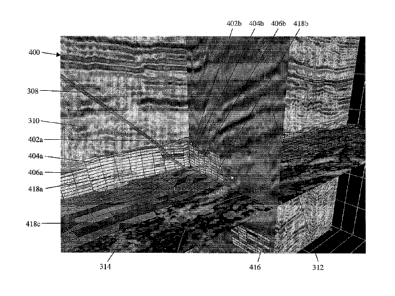
[0054] In FIG. 3, the results of step 202 are illustrated. The display
300 includes
three-dimensional data-objects such as horizons 302, 304, 306, seismic-data
slices
310, 312, 314, reservoir grids 316, 318 and a well path 308. It is noteworthy
that,
among other things, the horizon 302 and reservoir grid 318 appear to partially
block
16
= CA 02674820 2013-01-04
WO 2008/086196 PCT/US2008/050260
the view of the well path 308, making the location of the well path 308
difficult to
discern relative to the other objects in the display 300.
[0055] In step 204, at least one visualization surface is defmed
in the display using
the GUI tools and menu/interface software 104 described in reference to FIG.
1. A
visualization surface may be defined as any surface on which to display an
image of
an intersection with one or more objects removed from the display. A
visualization
surface may include, for example, any object within the display or any object
to be
added to the display. A visualization surface may also include, for example,
any
planar or non-planar object comprising three-dimensional seismic data or any
other
planar or non-planar object. A visualization surface may also be opaque or
transparent ¨ as determined by a default setting or using the GUI tools and
menu/interface software 104 described in reference to FIG. 1. In either case,
the
visualization surface displays at least an image of an intersection between
the
visualization surface and one of the objects removed from the display.
[0056] The visualization surface(s) defined in step 204 may be
implemented using
various techniques generally well known in the art and may include, for
example,
clipping pings planes that essentially "clip" or remove the seismic data
displayed
outside of the visualization surface(s). One technique, for example, is
described in
U.S. Patent No. 7,170,530. Another technique is described in U.S. Patent
No. 7,218,331. Other techniques are described in "VR User Interface: Closed
World Interaction" by Ching-Rong Lin and R. Bowen Loftin and
"Interaction with Geoscience Data in an Immersive Environment" by
Ching-Rong Lin, R. Bowen Loftin and H. Roice Nelson, Jr.,
17
CA 02674820 2009-07-03
WO 2008/086196 PCT/US2008/050260
include techniques for displaying an image of the contents of a bounding box
as the
bounding box is manipulated.
[0057] In step 205, at least one object of interest is selected from
the display using the
GUI tools and menu/interface software 104 described in reference to FIG. 1. An
object of interest may be selected for display and analysis or for removal
from the
display. An object of interest could be selected, for example, based on its
spatial
relationship with another object in the display or predefined using other
criteria to
allow the selection of objects that do not share a single defining
characteristic with
another object in the display. Default settings could therefore, be set, for
example, to
automatically and simultaneously display only the selected object(s) of
interest or to
remove only the selected object(s) of interest. Thus, the object(s) of
interest may be
collectively selected on the basis that the object(s) is/are unnecessary to
display and
should be removed from the display to better analyze the remaining object(s)
in the
display.
[0058] In order to more fully analyze the remaining object(s) in the
display relative to
the object(s) selected for removal from the display, an image of an
intersection
between the object(s) removed from the display and the visualization
surface(s) and
an image of an intersection between the object(s) remaining in the display and
the
visualization surface(s) or an image of the remaining object(s) are displayed
in step
206. The remaining object(s) in the display thus, may or may not intersect a
visualization surface. This step illustrates the location of removed objects
in the
display by depicting their intersection with the visualization surface(s).
[0059] In FIG. 4, the results of step 206 are illustrated. The display
400 includes
visualization surfaces 310, 312, 314, the remaining well path 308 and its
intersection
with the visualization surface 312. The display 400 also includes an image of
an
18
CA 02674820 2009-07-03
WO 2008/086196 PCT/US2008/050260
intersection between the horizons 302, 304, 306, which are removed from the
display
400 and the visualization surfaces 310, 312. Horizon 302, for example,
intersects
visualization surfaces 310, 312 at 402a, 402b, respectively. Horizon 304
intersects
visualization surfaces 310, 312 at 404a, 404b, respectively. And, horizon 306
intersects visualization surfaces 310, 312 at 406a, 406b, respectively. The
display
400 further includes an image of an intersection between the reservoir grids
316, 318,
which are removed from the display 400, and the visualization surfaces 310,
312 and
314. Reservoir grid 316, for example, intersects visualization surface 312 at
416.
Likewise, reservoir grid 318 intersects visualization surfaces 310, 312, 314
at 418a,
418b, 418c, respectively. The entire well path 308 in front of the
visualization
surfaces 310 and 312 is now visible. The display 400 further highlights the
positions
of horizons 302, 304, 306 and reservoir grids 316, 318 relative to the well
path 308.
The display 400 may also be manipulated in various ways to adjust the view of
the
well path 308 and its surroundings.
[0060] As the image is displayed in step 206, several options
described in reference to
steps 208 through 216 may be interactively controlled through the GUI tools
and
menu/interface software 104 to reduce the amount of extraneous three-
dimensional
data-objects and analyze the remaining object(s) in the display.
[0061] In step 208, the visualization surface(s) may be interactively
moved within the
display using the GUI tools and menu/interface software 104 described in
reference to
FIG. 1. As a visualization surface moves, the image of the intersection
between the
object(s) removed from the display and the visualization surface and the image
of the
intersection between the object(s) remaining in the display and the
visualization
surface or the remaining object(s) may be displayed. This step may be used to
view
fully displayed objects and the relative location of the object(s) removed
from the
19
CA 02674820 2009-07-03
WO 2008/086196
PCT/US2008/050260
display while a visualization surface is moved, which is illustrated by a
comparison of
the visualization surfaces 310, 312 and 314 in FIG. 4 and FIG. 5. Accordingly,
step
206 is repeated, in real-time, to provide a new display as the visualization
surface
moves.
[0062] In step 210, the image displayed in step 206 may be
interactively manipulated
(rotated or zoomed (in/out)) using the GUI tools and menu/interface software
104 to
view a different perspective of the image. As the image is rotated or zoomed,
the
image may be displayed. Accordingly, step 206 is repeated, in real-time, to
provide a
new display of a different perspective of the image.
[0063] In FIG. 5, compared to the display 400 in FIG. 4, the display
500 has been
zoomed (out) to view a different perspective of the well path 308 relative to
where
each horizon 302, 304, and 306 intersects the visualization surfaces 310 and
312.
Visualization surface 310, for example, intersects horizons 302, 304 and 306
at 502a,
504a and 506a, respectively. Visualization surface 312 intersects horizons
302, 304
and 306 at 502b, 504b and 506b, respectively. Because each visualization
surface
310, 312 and 314 has been moved in the display 500, compared to the display
400 in
FIG. 4, a different perspective of the well path 308 is illustrated relative
to where
each reservoir grid 316, 318 intersects a visualization surface 310, 312 or
314.
Reservoir grid 316, for example, intersects visualization surfaces 314 and 312
at 516a
and 516b, respectively. Likewise, reservoir grid 318 intersects visualization
surfaces
310 and 312 at 518a and 518b, respectively. In addition, another well path 520
is
visible.
[0064] In step 212, another visualization surface may be added to the
display using
the GUI tools and menu/interface software 104 described in reference to FIG.
I.
Accordingly, step 202 is repeated to add a new visualization surface to the
display.
CA 02674820 2009-07-03
WO 2008/086196 PCT/US2008/050260
[0065] In FIG. 6, for example, the display 600 includes a new
visualization surface
622, sometimes referred to as an opaque well section, that provides a
different
perspective of the display in FIG. 4. Alternatively, the visualization surface
622 may
be transparent. Visualization surface 622 intersects horizons 302, 304 and 306
at
602a, 604a and 606a, respectively. Visualization surface 312 intersects
horizons 302,
304 and 306 at 602b, 604b and 606b, respectively. Because each visualization
surface 310, 312 and 314 has been moved in the display 600, compared to the
display
400 in FIG. 4, a different perspective of the well path 308 is illustrated
relative to
where each reservoir grid 316, 318 intersects a visualization surface 310, 312
or 314.
Reservoir grid 316, for example, intersects visualization surfaces 314 and 312
at 616a
and 616b, respectively. Likewise, reservoir grid 318 intersects visualization
surfaces
622, 312 and 310 at 618a, 618b and 618c, respectively. In addition, an
intersection
between the new visualization surface 622 and another horizon (not shown) is
visible
at 620. The visualization surface 622 may be manipulated in the same manner as
the
visualization surface(s) described in reference to steps 208 and 210.
[0066] In FIG. 7, the display 700 includes another type of new
visualization surface
710, sometimes referred to as a bounding box, that provides a different
perspective of
the display in FIG. 6. The visualization surface 710 may be opaque or
transparent
and may be manipulated in the same manner as the visualization surface(s)
described
in reference to steps 208 and 210. The visualization surface 710 essentially
comprises
six separate planar visualization surfaces although only three are actually
displayed.
Visualization surface 622 intersects horizons 302, 304 and 306 at 602a, 604a
and
606a, respectively. Visualization surface 710 intersects horizons 302, 304 and
306 at
702, 704 and 706, respectively, Because each new visualization surface 622,
710 in
the display 700 replaces the former visualization surfaces 310, 312 and 314
illustrated
21
CA 02674820 2009-07-03
WO 2008/086196 PCT/US2008/050260
in FIG. 6, a different perspective of the well path 308 is illustrated
relative to where
each reservoir grid 316, 318 intersects a visualization surface 622 or 710.
Reservoir
grid 316, for example, intersects visualization surface 710 at 716. Likewise,
reservoir
grid 318 intersects visualization surfaces 622 and 710 at 618a and 718,
respectively.
The shape and size of the visualization surface 710, or any other
visualization surface,
may be interactively adjusted using the GUI tools and menu/interface software
104
described in reference to FIG. L
[0067] In step 214, another object may be added to the display using
the GUI tools
and menu/interface software 104 described in reference to FIG. 1. Accordingly,
step
202 is repeated to add another object to the display.
[0068] In step 216, the method 200 may be repeated by repopulating the
display at
step 202, which may also include removing an object or visualization surface
from the
display. The method 200 may also be repeated by defining another visualization
surface in the display at step 204 or by selecting another object of interest
in the
display at step 205.
[0069] Because the systems and methods described herein may be used to
selectively
and interactively analyze various three-dimensional data-objects, they may be
particularly useful for analyzing three-dimensional medical data or geological
data,
however, may also find utility for analyzing and interpreting any other type
of three-
dimensional data-objects.
[0070] While the present invention has been described in connection
with presently
preferred embodiments, it will be understood by those skilled in the art that
it is not
intended to limit the invention to those embodiments. It is therefore,
contemplated
that various alternative embodiments and modifications may be made to the
disclosed
22
CA 02674820 2015-06-23
embodiments without departing from the scope of the invention defined by the
appended claims
and equivalents thereof.
23