Note: Descriptions are shown in the official language in which they were submitted.
CA 02674975 2009-09-02
,
INTRAVASCULAR STENT HAVING IMPROVED DESIGN FOR
LOADING AND DEPLOYING
BACKGROUND OF THE INVENTION
1. Field of the Invention
The present invention relates to stents for use within a body
passageway or duct and more particularly to stents having improved strut
designs for
improved durability performance without sacrificing loading and deployment
ease.
2. Discussion of the Related Art
Percutaneous transluminal coronary angioplasty (PTCA) is a
therapeutic medical procedure used to increase blood flow through the
coronary arteries and may often be used as an alternative to coronary
by-pass surgery. In this procedure, an angioplasty balloon is inflated
within the stenosed vessel, or body passageway, in order to shear and
disrupt the wall components of the vessel to obtain an enlarged lumen.
With respect to arterial stenosed lesions, the relatively incompressible
plaque remains unaltered, while the more elastic medial and adventitial
layers of the body passageway stretch around the plaque. This process
typically produces dissection, or a splitting and tearing, of the body
passageway wall layers, wherein the intima, or internal surface of the
artery or body passageway, suffers fissuring. This dissection forms a
"flap" of underlying tissue which may reduce the blood flow through the
lumen, or block the lumen. Typically, the distending intraluminal
pressure within the body passageway can hold the disrupted layer, or
flap, in place. If the intimal flap created by the balloon dilation procedure
is not maintained in place against the expanded intima, the intimal flap
can fold down into the lumen and close off the lumen, or may even
become detached and enter the body passageway. When the intimal
CA 02674975 2013-09-04
2
flap closes off the body passageway, immediate surgery is necessary to
correct the problem.
Recently, transluminal prostheses have been widely used in the
medical arts for implantation in blood vessels, biliary ducts, or other
similar organs of the living body. These prostheses are commonly
known as stents and are used to maintain, open, or dilate tubular
structures. An example of a commonly used stent is given in U.S. Pat.
No. 4,733,665 filed by Palmaz on Nov. 7, 1985.
Such stents are often referred to as
balloon expandable stents. Typically the stent is made from a solid tube
of stainless steel. Thereafter, a series of cuts are made in the wall of the
stent. The stent has a first smaller diameter which permits the stent to
be delivered through the human vasculature by being crimped onto a
balloon catheter. The stent also has a second, expanded diameter,
upon the application, by a balloon catheter, from the interior of the
tubular shaped member of a radially, outwardly extending force.
However, such stents are often impractical for use in some vessels
such as the carotid artery. The carotid artery is easily accessible from
the exterior of the human body, and is often visible by looking at ones
neck. A patient having a balloon expandable stent made from stainless
steel or the like, placed in their carotid artery might be susceptible to
sever injury through day to day activity. A sufficient force placed on the
patients neck, such as by falling, could cause the stent to collapse,
resulting in injury to the patient. In order to prevent this, self expanding
stents have been proposed for use in such vessels. Self expanding
stents act like springs and will recover to their expanded or implanted
configuration after being crushed.
One type of self-expanding stent is disclosed in U.S. Pat. No.
4,665,771, which stent has a radially and axially flexible, elastic tubular
body with a predetermined diameter that is variable under axial
CA 02674975 2013-09-04
3
movement of ends of the body relative to each other and which
comprises of a plurality of individually rigid but flexible and elastic thread
elements defining a radially self-expanding helix. This type of stent is
known in the art as a "braided stent" and is so designated herein.
Placement of such stents in a body vessel may be achieved by a device
which comprise an outer catheter for holding the stent at its distal end,
and an inner piston which pushes the stent forward once it is in position.
However, braided stents have a number of disadvantages. They
typically do not have the necessary radial strength to effectively hold
open a diseased vessel. In addition, the plurality of wires or fibers used
to make such stents could become dangerous if separated from the
body of the stent, where it could pierce through the vessel. Therefore,
there has been a desire to have a self-expanding stent, which is cut
from a tube of metal, which is the common manufacturing method for
many commercially available balloon expandable stents. In order to
manufacture a self-expanding stent cut from a tube, the alloy used
would preferably have superelastic or psuedoelastic characteristics at
body temperature, so that it is crush recoverable.
TM
The prior art makes reference to the use of alloys such as Nitinol
(Ni-Ti alloy) which have shape memory and/or superelastic
characteristics in medical devices which are designed to be inserted into
a patient's body. The shape memory characteristics allow the devices to
be deformed to facilitate their insertion into a body lumen or cavity and
then be heated within the body so that the device returns to its original
shape. Superelastic characteristics on the other hand generally allow
the metal to be deformed and restrained in the deformed condition to
facilitate the insertion of the medical device containing the metal into a
patient's body, with such deformation causing the phase transformation.
Once within the body lumen the restraint on the superelastic member
may be removed, thereby reducing the stress therein so that the
superelastic member can return to its original un-deformed shape by the
CA 02674975 2009-08-07
4
transformation back to the original phase.
Alloys having shape memory/superelastic characteristics
generally have at least two phases. These phases are a martensite
phase, which has a relatively low tensile strength and which is stable at
relatively low temperatures, and an austenite phase, which has a
relatively high tensile strength and which is stable at temperatures
higher than the martensite phase.
Shape memory characteristics are imparted to the alloy by
heating the metal at a temperature above which the transformation from
the martensite phase to the austenite phase is complete, i.e. a
temperature above which the austenite phase is stable (the Af
temperature). The shape of the metal during this heat treatment is the
shape "remembered." The heat treated metal is cooled to a temperature
at which the martensite phase is stable, causing the austenite phase to
transform to the martensite phase. The metal in the martensite phase is
then plastically deformed, e.g. to facilitate the entry thereof into a
patient's body. Subsequent heating of the deformed martensite phase to
a temperature above the martensite to austenite transformation
temperature causes the deformed martensite phase to transform to the
austenite phase and during this phase transformation the metal reverts
back to its original shape if unrestrained. If restrained, the metal will
remain martensitic until the restraint is removed.
Methods of using the shape memory characteristics of these
alloys in medical devices intended to be placed within a patient's body
present operational difficulties. For example, with shape memory alloys
having a stable martensite temperature below body temperature, it is
frequently difficult to maintain the temperature of the medical device
containing such an alloy sufficiently below body temperature to prevent
the transformation of the martensite phase to the austenite phase when
the device was being inserted into a patient's body. With intravascular
CA 02674975 2009-08-07
devices formed of shape memory alloys having martensite-to-austenite
transformation temperatures well above body temperature, the devices
may be introduced into a patient's body with little or no problem, but they
must be heated to the martensite-to-austenite transformation
5 temperature which is frequently high enough to potentially cause tissue
damage and very high levels of pain.
When stress is applied to a specimen of a metal such as Nitinol
exhibiting superelastic characteristics at a temperature above which the
austenite is stable (i.e. the temperature at which the transformation of
martensite phase to the austenite phase is complete), the specimen
deforms elastically until it reaches a particular stress level where the
alloy then undergoes a stress-induced phase transformation from the
austenite phase to the martensite phase. As the phase transformation
proceeds, the alloy undergoes significant increases in strain but with
little or no corresponding increases in stress. The strain increases while
the stress remains essentially constant until the transformation of the
austenite phase to the martensite phase is complete. Thereafter, further
increases in stress are necessary to cause further deformation. The
martensitic metal first deforms elastically upon the application of
additional stress and then plastically with permanent residual
deformation.
If the load on the specimen is removed before any permanent
deformation has occurred, the martensitic specimen will elastically
recover and transform back to the austenite phase. The reduction in
stress first causes a decrease in strain. As stress reduction reaches the
level at which the martensite phase transforms back into the austenite
phase, the stress level in the specimen will remain essentially constant
(but substantially less than the constant stress level at which the
austenite transforms to the martensite) until the transformation back to
the austenite phase is complete, i.e. there is significant recovery in
strain with only negligible corresponding stress reduction. After the
CA 02674975 2009-08-07
6
transformation back to austenite is complete, further stress reduction
results in elastic strain reduction. This ability to incur significant strain
at
relatively constant stress upon the application of a load and to recover
from the deformation upon the removal of the load is commonly referred
to as superelasticity or pseudoelasticity. It is this property of the material
which makes it useful in manufacturing tube cut, self-expanding stents.
The prior art makes reference to the use of metal alloys having
superelastic characteristics in medical devices which are intended to be
inserted or otherwise used within a patient's body. See for example,
U.S. Pat. No. 4,665,905 (Jervis) and U.S. Pat. No. 4,925,445 (Sakamoto
et al.).
However, the prior art has yet to disclose ideal tube cut, self
expanding stents. In addition, a number of the prior art stents lacked the
necessary rigidity or hoop strength to keep the body vessel open. In
addition, a number of the prior art stents have large openings at their
expanded diameter. The smaller the openings are on an expanded
stent, the more plaque or other deposits it can trap between the stent
and the vessel wall. Trapping these deposits is important to the
continuing health of the patient in that it helps prevent stokes as well as
helps prevents restenosis of the vessel it is implanted into. In addition,
many of the prior art stents have failed to optimize stent mechanical
performance characteristics relative to their size for percutaneous
delivery.
SUMMARY OF THE INVENTION
The present invention overcomes the difficulties as briefly described
above.
In accordance with one exemplary embodiment, the present invention is
directed to an intraluminal device for maintaining vessel patency. The device
CA 02674975 2014-06-09
7
comprising a substantially tubular structure having a first diameter for
insertion
into a vessel and a second diameter for deployment in a vessel, the
substantially tubular structure being formed from a plurality of hoops,
wherein
adjacent hoops are connected by one or more bridges, each hoop comprising
a plurality of longitudinally arranged struts, each strut having two opposing
ends and a center therebeween, the width of the struts being greater at its
opposing ends than at its center, and a plurality of loops connecting the
plurality of struts to form a substantially s-shaped pattern, and wherein one
or
more struts in each hoop comprises an one or more circumferentially extending
protrusions proximate the center thereof.
In accordance with an aspect of the present invention, there is provided
an intraluminal device for maintaining vessel patency comprising a
substantially
tubular structure having a first diameter for insertion into a vessel and a
second
diameter for deployment in a vessel, the substantially tubular structure being
formed from a plurality of hoops, wherein adjacent hoops are connected by
one or more bridges, each hoop comprising a plurality of longitudinally
arranged struts, each strut having two opposing ends and a center
therebetween, the width of the struts being greater at its opposing ends than
at
its center, and a plurality of loops connecting the plurality of struts to
form a
substantially s-shaped pattern, and wherein one or more struts in each hoop
comprises an one or more circumferentially extending protrusions proximate
the center thereof.
In accordance with another aspect of the present invention, there is
provided an intraluminal device for maintaining vessel patency comprising a
substantially tubular structure having a first diameter for insertion into a
vessel
and a second diameter for deployment in a vessel, the substantially tubular
structure being formed from a plurality of hoops, wherein adjacent hoops are
connected by one or more bridges, each hoop comprising a plurality of
longitudinally arranged struts, each strut having two opposing ends and a
center the struts having a wider portion at their opposing ends tapering to a
narrower region between the wider portions such that a gap is formed between
= CA 02674975 2014-06-09
7a
two adjacent struts between their narrower regions when the tubular structure
is in the first diameter state, and a plurality of loops connecting the
plurality of
struts to form a substantially s-shaped pattern, and wherein one or more
struts
in each hoop comprises an one or more circumferentially extending protrusions
proximate located at the narrower region of each strut, wherein said
circumferentially extending protrusions are symmetric about the longitudinal
axis of each individual strut such that each protrusion on each strut contacts
a
protrusion on each adjacent strut when the tubular structure is the first
diameter state such that the combined length of the contacting protrusions is
approximately equal to the distance created by the gap formed between the
narrow regions between two adjacent struts, and wherein each protrusion is
configured to prevent axial displacement of each strut and improve fatigue
resistance when the tubular structure is in the first diameter state and the
protrusions are in contact with each other.
In accordance with another aspect of the present invention, there is
provided an intraluminal device for maintaining vessel patency comprising a
substantially tubular structure having a first diameter for insertion into a
vessel
and a second diameter for deployment in a vessel, the substantially tubular
structure being formed from a plurality of hoops, wherein adjacent hoops are
connected by one or more bridges, each hoop comprising a plurality of
longitudinally arranged struts, each strut having two opposing ends and a
center therebetween the struts having a wider portion at their opposing ends
tapering to a narrower region between the wider portions such that a gap is
formed between two adjacent struts between their narrower regions when the
tubular structure is in the first diameter state, and a plurality of loops
connecting the plurality of struts to form a substantially s-shaped pattern,
and
wherein one or more struts in each hoop comprises one or more
circumferentially extending protrusions located at the narrower region of each
strut, wherein the one or more circumferentially extending protrusions are
configured to abut one another on adjacent struts when the intraluminal device
is in the first diameter state such that the combined length of the abutting
protrusions is approximately equal to the distance created by the gap formed
CA 02674975 2014-06-09
7b
between the narrow regions between two adjacent struts and wherein the one
or more circumferentially extending protrusions interlock with one another on
adjacent struts when the intraluminal device is in the first diameter state to
prevent axial displacement of each strut and improve fatigue resistance when
the tubular structure is in the first diameter state and the protrusions are
interlocked.
The present invention utilizes small additional elements or features
added to tapered struts of a stent to increase the pushability of the stent
during
the process of loading the stent into a delivery device, and deployment of the
stent without complicating delivery system features. For example, the delivery
of a highly flexible stent may require the utilization of stent retention and
securement features built into one or both the stent and the stent delivery
system, such as maturing and/or interlocking features, which by necessity,
would have to be aligned with one another. As described in detail herein,
tapered struts offer an advantage over straight struts by distributing the
stress
over the length of the strut, and thus minimize local stress concentrations
near
the apex or loop of the strut. This improved distribution results in an
increase
in stent fatigue resistance. Also described in detail herein, while stent
flexibility
is paramount and may be optimized/achieved with tapered struts, use of
tapered struts may potentially result in buckling during stent loading into
the
delivery system. Accordingly, the present invention utilizes added features to
the tapered struts that stabilize the gaps between struts when the stent is
loaded into the delivery system. These additional features solve the problem
without adversely affecting the stress distribution. In fact, slight
improvement in
fatigue resistance occurs when these features are incorporated as part of the
tapered strut as confirmed using finite element analysis.
CA 02674975 2009-08-07
,
8
The present invention is a simple solution to the potential buckling problem
associated with loading. The additional elements are easily cut as part of the
overall manufacturing process and have no known adverse effects on stent
performance.
BRIEF DESCRIPTION OF THE DRAWINGS
The foregoing and other features and advantages of the invention
will be apparent from the following, more particular description of
preferred embodiments of the invention, as illustrated in the
accompanying drawings.
Figure 1 is a simplified partial cross-sectional view of a stent
delivery apparatus having a stent loaded therein, which can be used
with a stent made in accordance with the present invention.
Figure 2 is a view similar to that of Figure 1 but showing an
enlarged view of the distal end of the delivery apparatus in accordance
with the present invention.
Figure 3 is a perspective view of a stent made in accordance
with the present invention, showing the stent in its compressed state.
Figure 4 is a sectional, flat view of the stent shown in Figure 1.
Figure 4A is an enlarged view of section of the stent shown in
Figure 4.
Figure 5 is a perspective view of the stent shown in Figure 1 but
showing it in its expanded state.
Figures 6A and 6B are sectional, flat views of a first exemplary
embodiment of a stent having modified elements in accordance with the
CA 02674975 2009-08-07
A
9
present invention showing the expanded and compressed
states/configuration respectfully.
Figure 7 is a sectional, flat view of a second exemplary
embodiment of a stent in the expanded state having modified elements
in accordance with the present invention.
Figures 8A and 8B are sectional, flat views of a third exemplary
embodiment of a stent having modified elements in accordance with the
present invention showing the expanded and compressed
states/configuration respectfully.
Figure 9 is a sectional, flat view of a fourth exemplary
embodiment of a stent in the expanded state having modified elements
in accordance with the present invention.
Figures 10A and 10B are sectional, flat views of a fifth exemplary
embodiment of a stent having modified elements in accordance with the
present invention showing the expanded and compressed
states/configuration respectfully.
DETAILED DESCRIPTION OF THE PREFERRED EMBODIMENTS
Referring now to the figures wherein like numerals indicate the
same element throughout the views, there is shown in Figures 3, 4, and
4A a stent 50 made in accordance with the present invention. Figures 3
and 4 show stent 50 in its un-expanded or compressed state. Stent 50 is
preferably made from a superelastic alloy such as Nitinol. Most
preferably, stent 50 is made from an alloy comprising from about 50.5
percent (as used herein these percentages refer to atomic percentages)
Ni to about 60 percent Ni, and most preferably about 55 percent Ni, with
the remainder of the alloy Ti. Preferably, the stent is such that it is
CA 02674975 2009-08-07
a
superelastic at body temperature, and preferably has an Af in the range
from about twenty-four degrees Celsius to about thirty-seven degrees
Celsius. The superelastic design of the stent makes it crush recoverable
which, as discussed above, can be used as a stent or frame for any
5 number of vascular devices for different applications.
Stent 50 is a tubular member having front and back open ends 81
and 82 and a longitudinal axis 83 extending therebetween. The tubular
member has a first smaller diameter, Figures 3 and 4, for insertion into a
10 patient and navigation through the vessels, and a second larger
diameter, Figures 5 and 6, for deployment into the target area of a
vessel. The tubular member is made from a plurality of adjacent hoops
52, Figure 3 showing hoops 52(a)-52(d), extending between the front
and back ends 81 and 82. The hoops 52 include a plurality of
longitudinal struts 60. As seen from Figure 4A, each strut 60 has two
opposing ends 90 and 92 and a center 94 therebetween. The ends 90
and 92 of the struts 60 are curved or bent so as to form a plurality of
loops 62, which connect adjacent struts. The struts are so connected at
their opposite ends so as to form an S or Z shape pattern. The loops 62
are preferably curved, substantially semi-circular and symmetrical
sections.
Stent 50 further includes a plurality of bridges 70 which connect
adjacent hoops 52 and that may best be described by referring to Figure
4. Each bridge 70 has two ends, wherein one end is attached to one
strut and/or loop, and another end attached to a strut and/or loop on an
adjacent hoop 52. While the Figures show the bridges 70 connecting the
loop 62 of one bridge to the nearest loop 62 on the adjacent hoop 52,
this does not need to be so. The bridge 70 could be longer and extend
the length of many struts between its connection point on adjacent
hoops 52. The bridges 70 are curved, and are attached to loops 62 at
points off center of the radius of curvature of the loops 62.
CA 02674975 2009-08-07
11
The above described geometry helps to better distribute strain
throughout the stent, prevents metal to metal contact when the stent is
bent, and minimizes the opening size between the features, struts, loops
and bridges. The number of and nature of the design of the struts, loops
and bridges are important factors when determining the working
properties and fatigue life properties of the stent. It was previously
thought that in order to improve the rigidity of the stent, that struts
should be large, and therefore there should be fewer struts per hoop.
However, it has now been discovered that stents having smaller struts
and more struts per hoop actually improve the construction of the stent
and provide greater rigidity. Preferably, each hoop has between twenty-
four to thirty-six or more struts. It has been determined that a stent
having a ratio of number of struts 60 per hoop 52 to strut length L (in
inches) which is greater than four hundred has increased rigidity over
prior art stents which typically had a ratio of under two hundred. The
length of a strut 60 is measured in its compressed state parallel to the
longitudinal axis 83 of the stent.
The present invention may best be understood by referring back
to Figures 4 and 4A. As seen from Figure 4A, each strut has a width W,
measured in a substantially circumferential direction, which is greater at
its ends 90 and 92, and points adjacent thereto, than in its center 94.
Preferably, the width W tapers substantially continuously from each of
the ends 90 and 92 to the center 94. The effect of this tapering will be to
cause a greater resistance to deformation at the loops 62 (where the
bending moments are high), and to make the overall strain deformation
more uniform. The ideal reduction in width is a complex function, driven
by efforts to keep the bending radius constant. Bending of rectangular
beam is controlled by the formula:
1/R=12FL/(ETW3)
where R is the radius of curvature of the loops (to remain constant), F is
CA 02674975 2009-08-07
i
..
12
the applied force, L the distance from the endpoint, E is Young's
modulus, T the thickness of the strut (shown in Figure 3) and W the strut
width (shown in Figure 4A). Thus as a guideline, the strut width W
should vary as the cube root of the distance from either of the ends, 90
or 92. That is, at any point along the center 94 of a strut 60 the width
should be proportional to the cube root of the distance from the end
point that is closest to strut ends, 90 or 92. However, any taper, even a
simple linear tapered reduction in width would still represent a
substantial improvement over a constant width strut.
Because the struts are wider at their ends, the overall stent can
handle greater compressive and expanding forces. Therefore, stents
having smaller delivery diameters and greater expanded diameters can
be made while still being extremely flexible over the entire stent length.
In addition, the stent can handle greater fatigue stresses, which could
result in a longer lasting and stronger stent.
As seen from Figure 5, the geometry of the stent changes quite
significantly as a stent is deployed from its un-expanded state to its
expanded state. As a stent undergoes diametric change, the strut angle
and strain levels in the loops and bridges are effected. Preferably, all of
the stent features will strain in a predictable manor so that the stent is
reliable and uniform in strength. In addition, it is preferable to minimize
the maximum strain experienced by struts loops and bridges, since
Nitinol properties are more generally limited by strain, rather than by
stress as most materials are. As will be discussed in greater detail
below, the stent sits in the delivery system in its un-expanded or
compressed state as shown in Figure 3. As the stent is deployed, it is
allowed to expand towards it's expanded state, as shown in Figure 5,
which preferably has a diameter which is the same or larger than the
diameter of the target vessel. Nitinol stents made from wire (as opposed
to being cut from a tube) deploy in much the same manor and are
dependent upon the same design constraints as laser cut stents.
CA 02674975 2009-08-07
13
Stainless steel stents deploy similarly in terms of geometric changes
although they are assisted with forces from balloons or other devices.
In trying to minimize the maximum strain experienced by the
features (struts 60, loops 62 and bridges 70), the present invention
utilizes structural geometry's which distribute strain to areas of the stent
which are less susceptible to failure than others. For example, one of
the most vulnerable areas of the stent is the inside radius of the
connecting loops 62. The connecting loops 62 undergo the most
deformation of all the stent features. The inside radius of the loop 62
would normally be the area with the highest level of strain on the stent.
This area is also critical in that it is usually the smallest radius on the
stent. Stress concentrations are generally controlled or minimized by
maintaining the largest radii possible, and by dual tapering the width of
struts as disclosed above. Similarly, we want to minimize local strain
concentrations on the bridge 70 and bridge connection points. One way
to accomplish this is to utilize the largest possible radii while maintaining
feature widths which are consistent with applied forces. Another
consideration is to minimize the maximum open area of the stent.
Efficient utilization of the original tube from which the stent is cut
increases stent strength and its ability to trap embolic material.
As mentioned above, bridge geometry changes both as a stent is
deployed from its compressed state to its expanded state and from its
expanded state to a compressed state. As a stent undergoes diametric
change, strut angle and loop strain is effected. Since the bridges 70 are
connected to either the loops 62, struts 60 or both, they are effected.
Twisting of one end of the stent with respect to the other, while loaded in
the stent delivery system, should be avoided. Local torque delivered to
the bridge ends displaces the bridge geometry. If the bridge design is
duplicated around the stent perimeter, this displacement causes
rotational shifting of the two hoops being connected by the bridges. If
the bridge design is duplicated throughout the stent, this shift will occur
CA 02674975 2009-08-07
,
14
down the length of the stent. This is a cumulative effect as one
considers rotation of one end with respect to the other upon
deployment. A stent delivery system, such as the one described below,
will deploy the distal end first, then allow the proximal end to expand. It
would be undesirable to allow the distal end to anchor into the vessel
wall while holding the stent fixed in rotation, then release the proximal
end. In doing so, this could cause the stent to twist or whip in rotation to
equilibrium after it is at least partially deployed within the vessel. Such
whipping action could cause damage to the vessel.
However, in accordance with an exemplary embodiment of the
present invention, as shown in the figures, this design reduces the
chance of such events from happening when deploying the stent. By
mirroring the bridge geometry longitudinally down the stent, the
rotational shift of the Z-sections can be made to alternate and will
minimize large rotational changes between any two points on respective
hoops 52 on a given stent during deployment or constraint. That is the
bridges 70 connecting loop 52(b) to loop 52(c) are angled upwardly from
left to right, while the bridges 70 connecting loop 52(c) to loop 52(d) are
angled downwardly from left to right. This alternating pattern is repeated
down the length of the stent. This alternating pattern of bridge slopes
improves the torsional characteristics of the stent so as to minimize any
twisting or rotation of the stent with respect to any two hoops 52. This
alternating bridge slope is particularly beneficial if the stent starts to
twist
in vivo. As the stent twists, the diameter of the stent will change.
Alternating bridge slopes tend to minimize this effect. The diameter of a
stent having bridges 70 which are all sloped in the same direction will
tend grow if twisted in one direction and shrink if twisted in the other
direction. With alternating bridge slopes this effect is minimized and
localized.
The above-described feature is particularly advantageous for
stents having large expansion ratios, which in turn requires them to have
CA 02674975 2009-08-07
,
extreme bending requirements where large elastic strains are required.
Nitinol can withstand extremely large amounts of elastic strain
deformation, so the above features are well suited to stents made from
this alloy. This feature allows for maximum utilization of Ni--Ti or other
5 material capabilities to enhance radial strength, improve stent strength
uniformity, improve fatigue life by minimizing local strain levels, allow for
smaller open areas which enhance entrapment of embolic material, and
improve stent apposition in irregular vessel wall shapes and curves.
10 Preferably, stents are laser cut from small diameter tubing. For
prior art stents, this manufacturing process lead to designs with
geometric features, such as struts, loops and bridges, having axial
widths which are larger than the tube wall thickness T (shown in Figure
3). When the stent is compressed, most of the bending occurs in the
15 plane that is created if one were to cut longitudinally down the stent
and
flatten it out. However, for the individual bridges, loops and struts, which
have widths greater than their thickness, they have a greater resistance
to this in-plane bending than they do to out of plane bending. Because
of this, the bridges and struts tend to twist, so that the stent as a whole
can bend more easily. This twisting is a buckling condition which is
unpredictable and can cause potentially high strain.
However, this problem has been solved in a preferred exemplary
embodiment of the present invention, shown in the figures. For the
present invention, it is preferred that the maximum widths of the struts
60, hoops 52 and bridges 70 are equal to or less than the wall thickness
of the tube. Therefore, substantially all bending and, therefore, all
strains are "out of plane." This minimizes twisting of the stent which
minimizes or eliminates buckling and unpredictable strain conditions.
The feature is particularly advantageous for stents having large
expansion ratios, which in turn requires them to have extreme bending
requirements where large elastic strains are required. Nitinol can
withstand extremely large amounts of elastic strain deformation, so the
CA 02674975 2009-08-07
,
,
16
above features are well suited to stents made from this alloy as
described above.
While the current invention may be either a self expanding or
balloon expandable stent, and may be made from any number of
materials known in the art, including stainless steel, as mentioned
above, it is preferred that the stent of the present invention be made
from a superelastic alloy and most preferably made of an alloy material
having greater than 50.5 atomic percent Nickel and the balance
titanium. Greater than 50.5 atomic percent Nickel allows for an alloy in
which the temperature at which the martensite phase transforms
completely to the austenite phase (the Af temperature) is below human
body temperature and preferably is about twenty-four degrees Celsius to
about thirty-seven degrees Celsius so that austenite is the only stable
phase at body temperature.
In manufacturing the Nitinol stent, the material is first in the form
of a tube. Nitinol tubing is commercially available from a number of
suppliers. The tubular member is then loaded into a machine which will
cut the predetermined pattern of the stent, which was discussed above
and is shown in the Figures, into the tube. Machines for cutting patterns
in tubular devices to make stents or the like are well known to those of
ordinary skill in the art and are commercially available. Such machines
typically hold the metal tube between the open ends while a cutting
laser, preferably under microprocessor control, cuts the pattern. The
pattern dimensions and styles, laser positioning requirements, and other
information are programmed into a microprocessor which controls all
aspects of the process. After the stent pattern is cut, the stent is treated
and polished using any number of methods well known to those skilled
in the art. Lastly, the stent is then cooled until it is completely
martensitic, crimped down to its un-expanded diameter and then loaded
into the sheath of the delivery apparatus.
CA 02674975 2013-09-04
17
It is believed that many of the advantages of the present
invention may be better understood through a brief description of a
delivery apparatus for the stent, as shown in Figures 1 and 2. Figures 1
and 2 show a self-expanding stent delivery apparatus 1 for a stent made
in accordance with the present invention. Apparatus 1 comprises inner
and outer coaxial tubes. The inner tube is called the shaft 10 and the
outer tube is called the sheath 40. Shaft 10 has proximal and distal ends
12 and 14 respectively. The distal end 14 of the shaft terminates at a
luer lock hub 5. Preferably, shaft 10 has a proximal portion 16 which is
made from a relatively stiff material such as stainless steel, Nitinol, or
any other suitable material, and an distal portion 18 which is made from
TM TM TM
a polyethylene, polyimide, pellethane, Pebax, Vestamid, Cristamid,
TM
Grillamid or any other suitable material known to those of ordinary skill in
the art. The two portions are joined together by any number of means
known to those of ordinary skill in the art. The stainless steel proximal
end gives the shaft the necessary rigidity or stiffness it needs to
effectively push out the stent, while the polymeric distal portion provides
the necessary flexibility to navigate tortuous vessels.
The distal portion 18 of the shaft has a distal tip 20 attached
thereto. The distal tip 20 has a proximal end 34 whose diameter is
substantially the same as the outer diameter of the sheath 40. The distal
tip tapers to a smaller diameter from its proximal end to its distal end,
wherein the distal end 36 of the distal tip has a diameter smaller than
the inner diameter of the sheath. Also attached to distal portion 18 of
shaft 10 is a stop 22 which is proximal to the distal tip 20. Stop 22 may
be made from any number of materials known in the art, including
stainless steel, and is even more preferably made from a highly
radiopaque material such as platinum, gold tantalum. The diameter of
stop 22 is substantially the same as the inner diameter of sheath 40,
and would actually make frictional contact with the inner surface of the
sheath. Stop 22 helps to push the stent out of the sheath during
deployment, and helps the stent from migrating proximally into the
CA 02674975 2013-09-04
18
sheath 40.
A stent bed 24 is defined as being that portion of the shaft
between the distal tip 20 and the stop 22. The stent bed 24 and the
stent 50 are coaxial so that the portion of shaft 18 comprising the stent
bed 24 is located within the lumen of the stent 50. However, the stent
bed 24 does not make any contact with stent 50 itself. Lastly, shaft 10
has a guidewire lumen 28 extending along its length from its proximal
end 12 and exiting through its distal tip 20. This allows the shaft 10 to
receive a guidewire much in the same way that an ordinary balloon
angioplastly catheter receives a guidewire. Such guidewires are well
known in art and help guide catheters and other medical devices
through the vasculature of the body.
Sheath 40 is preferably a polymeric catheter and has a proximal
end 42 terminating at a hub 152. Sheath 40 also has a distal end 44
which terminates at the proximal end 34 of distal tip 20 of the shaft 18,
when the stent is in its fully un-deployed position as shown in the
Figures. The distal end 44 of sheath 40 includes a radiopaque marker
band 46 disposed along its outer surface. As will be explained below,
the stent is fully deployed when the marker band 46 is lined up with
radiopaque stop 22, thus indicating to the physician that it is now safe to
remove the apparatus 1 from the body. Sheath 40 preferably comprises
an outer polymeric layer and an inner polymeric layer. Positioned
between outer and inner layers a braided reinforcing layer. Braided
reinforcing layer is preferably made from stainless steel. The use of
braided reinforcing layers in other types of medical devices can be found
in U.S. Pat. No. 3,585,707 issued to Stevens on Jun. 22, 1971, U.S.
Pat. No. 5,045,072 issued to Castillo et al. on Sep. 3, 1991, and U.S.
Pat. No. 5,254,107 issued to Soltesz on Oct. 19, 1993.
Figures 1 and 2 show the stent 50 as being in its fully an-
CA 02674975 2009-08-07
,
19
deployed position. This is the position the stent is in when the apparatus
1 is inserted into the vasculature and its distal end is navigated to a
target site. Stent 50 is disposed around stent bed 24 and at the distal
end 44 of sheath 40. The distal tip 20 of the shaft 10 is distal to the
distal end 44 of the sheath 40, and the proximal end 12 of the shaft 10
is proximal to the proximal end 42 of the sheath 40. The stent 50 is in a
compressed state and makes frictional contact with the inner surface 48
of the sheath 40.
When being inserted into a patient, sheath 40 and shaft 10 are
locked together at their proximal ends by a Touhy Borst valve 8. This
prevents any sliding movement between the shaft and sheath which
could result in a premature deployment or partial deployment of the
stent. When the stent 50 reaches its target site and is ready for
deployment, the Touhy Borst valve 8 is opened so that that the sheath
40 and shaft 10 are no longer locked together.
The method under which apparatus 1 deploys stent 50 should be
readily apparent. The apparatus 1 is first inserted into a vessel so that
the stent bed 24 is at a target diseased site. Once this has occurred the
physician would open the Touhy Borst valve 8. The physician would
then grasp the proximal end 12 of shaft 10 so as to hold it in place.
Thereafter, the physician would grasp the proximal end 42 of sheath 40
and slide it proximal, relative to the shaft 40. Stop 22 prevents the stent
50 from sliding back with the sheath 40, so that as the sheath 40 is
moved back, the stent 50 is pushed out of the distal end 44 of the
sheath 40. Stent deployment is complete when the radiopaque band 46
on the sheath 40 is proximal to radiopaque stop 22. The apparatus I
may now be withdrawn through stent 50 and removed from the patient.
As described above, tapered stents better distribute stresses
along the strut as opposed to the old design which has a high axial
columnar stiffness, but which has its stresses concentrated proximate
CA 02674975 2009-08-07
,
,
the loops. Each strut of a stent is designed to optimize the mechanical
performance requirements of the stent while overcoming the size
limitations imposed by the small profile of the blood vessels into which
the stents are implanted.
5
The tapered strut design disclosed herein is directed toward
maximizing the stent's axial and radial fatigue resistance, thus
maximizing the stent's ability to resist the cyclical radial loading due to
the pulsatile forces in the cardiovascular system as well as the axial,
10 bending, crush and torsional loads due to forces external to the
blood
vessel in which the stent is implanted. These properties are crucial for
stent performance since the overall fatigue resistance is vital for the long
term integrity of the stent. The long term integrity of the stent, in turn, is
crucial for providing the long term patentcy of the treated blood vessel.
While the tapered design for the struts spreads the strain
distribution over the length of the struts, it also creates a potential for
difficulties in loading the stent into the stent delivery system. Due to the
tapering of the struts, larger gaps between struts remain when the stent
is fully compressed/crimped as compared to the older straight strut
design. Accordingly, when the compressed/crimped stent is pushed or
loaded into the delivery system, the thinned struts may tend to buckle
and/or twist which in turn may compress and/or deform the stent. This
compression and/or deformation may further increase the loading
resistance and may even potentially prevent the stent from being loaded
onto the delivery system. In addition, increased resistance may be
encountered during delivery of the stent into the vasculature if excessive
deformation of the stent occurs.
While mating delivery system elements may be added in an
alternative approach, it is extremely difficult to align the elements of the
modified delivery system with the strut gaps.
CA 02674975 2009-08-07
21
In accordance with another exemplary embodiment, features may
be added to the stent in localized areas, thereby increasing the
pushability and/or column strength as well as the fatigue resistance of
the stent while maintaining its flexibility during delivery and implantation,
and without loosing any of the benefit created by the tapered strut
design as described herein.
Referring to Figures 6A and 6B, there is illustrated a first
exemplary embodiment of a stent segment 600 having an improved
tapered strut design, shown in both the "as cut" state (Figure 6A) and
the "as crimped" state (Figure 6B), in accordance with the present
invention. The differences in shape between the stent segments
illustrated in Figures 6A and 6B are due to the change in diameter and
associated forces acting thereon. The shape of the strut in one state,
for example, "as cut" is sufficient to fully describe the shape and all other
design parameters of the stent. In this first exemplary embodiment, one
set of tapered struts 602 comprises no protrusions, while a second set
of tapered struts 604 comprises protrusions 606. Essentially, in this first
exemplary embodiment, every other strut comprises a protrusion 606
located substantially midway between the strut ends both on the
superior and inferior surfaces of the strut itself.
The protrusions 606 may comprise any suitable shape and or
configuration. In the illustrated first exemplary embodiment, the
protrusions 606 extend from both sides of the struts 604 like wings. The
length of the extension of each protrusion 606 is approximately equal to
the distance created by the gap 608 in the compressed state between
adjacent tapered struts 602, 604 where the gap is the greatest. In other
words, it is the gap created where each tapered strut is at its thinnest.
In this way, the protrusions 606 will prevent side-to-side movement and
thus will produce uniform and pushable stent elements. While this
design prevents side-to-side strut movement, it also improves the
CA 02674975 2009-08-07
,
,
22
fatigue resistance of the stent as evidenced by finite element analysis as
described in detail below.
The protrusions 606 are preferably positioned at or near the
center or thinnest section of the tapered struts 604. If the taper is not
uniform, the protrusions 606 may be positioned at the thinnest point and
not necessarily at the center. The protrusions 606 may be elements
added after the stent is cut or most preferably, be cut out of the tube
when all other elements and/or features of the stent are cut.
In accordance with another exemplary embodiment, extended
tips or protrusions may be added to one or more of the loops not having
bridges connecting adjacent hoops. Referring to Figure 7, there is
illustrated a stent segment 700 having the protrusions 606 described
above with respect to Figures 6A and 6B and extended tips 702. The
extended tips 702 function to minimize axial compression upon loading,
if required. As illustrated, only the loops 704 not having bridges 706
have the extended tips 702. Although, the extended tips 702 are only on
every other hoop 708 so that each extended tip 702 makes contact with
an adjacent loop 704 and not any other extended tip 702 it is envisioned
that the extended tip 702 may be on either hoop and may even be
present on both hoops if desired. The extended tips 702 may comprise
any suitable configuration. In the exemplary embodiment, the tips 702
comprises a substantially anvil shape. In addition, as with the
protrusions 606, the extended tips 702 may be a feature that is added to
the loop or most preferably, laser cut from the same tube as every other
element and/or feature.
In accordance with yet another exemplary embodiment,
protrusions may be added to all of the tapered struts, in contrast with the
device illustrated in Figures 6A and 6B. Figures 8A and 8B illustrate this
exemplary embodiment of the stent segment 800 in both the "as cut"
state (Figure 8A) and the "as crimped" state. In this exemplary
CA 02674975 2009-08-07
23
embodiment, the protrusions 802 are smaller in circumferential size as
compared to those in Figures 6A and 6B. The protrusions 802 are
smaller since they are on each of the tapered struts 804 and arranged
so that they make contact with one another as illustrated in Figure 8B.
Given that they make contact with one another, they can be
approximately half the size of those illustrated in Figures 6A and 6B and
cover the equivalent distance of the gap created between tapered struts,
yet still provide the same functionality.
It is interesting to note that in performing finite element analysis of
the stents illustrated in Figure 6A, 6B and Figures 8A, 8B, the maximum
alternating strain which is a measure of fatigue resistance for a -5
percent to a +5 percent axial fatigue loading is 0.26 percent as
compared to 0.27 percent for a tapered strut with no protrusions under
equivalent loading. The lower the alternating strain of the device, the
more fatigue resistant it becomes. From this analysis, it appears that
while the tapered strut design described herein maximizes the stent's
axial and radial fatigue resistance as compared to a straight strut, there
may also be additional increase in fatigue resistance by adding the
protusions which also relieves the problem of loading by increasing the
column strength of the stent construct as described in detail herein.
In accordance with yet another alternate exemplary embodiment,
multiple protrusions may be positioned one or more struts. Figure 9
illustrates a stent segment 900 having two wing shaped protrusions 902
extending from every other strut 904. The remaining struts 906 have no
protrusions. Essentially, this exemplary embodiment is identical to the
design illustrated in Figures 6A and 6B except for the number of
protrusions and their spacing. Given that there are two protrusions 902,
they are spaced apart and not centered as in the device illustrated in
Figures 6A and 6B. More than one protrusion 902 per stent 904 may
reduce the maximum alternating strain making the device more fatigue
resistant.
CA 02674975 2009-08-07
,
I
24
In all of the above described devices, the addition of protrusion(s)
addresses the difficulties associated with the tapered strut design as
well as slightly increasing the fatigue resistance which may be further
increased utilizing multiple protrusions. In alternate exemplary
embodiments, the protrusions may take on other shapes and/or
configurations. For example, the protrusions may interlock or lock onto
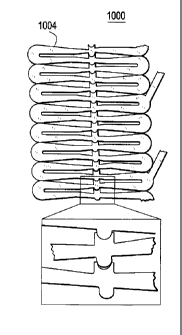
the adjacent tapered struts. Referring to Figures 10A and 10B, there is
illustrated this exemplary embodiment. As illustrated, a stent segment
1000 has interlocking protrusions 1002. Figure 10 illustrates the stent
1004 in the compressed state and Figure 10B illustrates the stent 1004
in the expanded state.
Although shown and described is what is believed to be the most
practical and preferred embodiments, it is apparent that departures from
specific designs and methods described and shown will suggest
themselves to those skilled in the art and may be used without departing
from the spirit and scope of the invention. The present invention is not
restricted to the particular constructions described and illustrated, but
should be constructed to cohere with all modifications that may fall
within the scope of the appended claims.