Note: Descriptions are shown in the official language in which they were submitted.
- --
CA 02675217 2009-08-11
70 TISSUE-MIMICKING PHANTOM FOR PROSTATE CANCER BRACHYTHERAPY
Field of the Invention
The present invention relates to a phantom for prostate cancer brachytherapy.
Background of the Invention
The prostate is a gland about the size and shape of a walnut. The prostate is
located between the pubic bone and rectum. It surrounds the upper part of the
urethra,
the tube that carries urine from the bladder. As a man ages, his prostate may
change.
Non-cancerous (benign) growths may form. Or some cells may change into
precancerous
cells and cancerous cells may form a malignant tumor. For some men, cancerous
cells
may form within the prostate but grow too slowly to cause problems. In other
cases,
cancerous tumors may grow inside the prostate, then spread.
Prostate cancer is the most frequently diagnosed cancer and the second leading
cause of death due to cancer in Canadian men [1]. During the last decade,
image-guided
prostate brachytherapy has become a mainstream treatment option [2,3].
Brachytherapy
includes a combination of fast imaging during the insertion of hollow needles
(size 18 ga)
to place radioactive seeds in the diseased tissue. The radioactive seeds
(about 120)
destroy only a small surrounding tissue envelope. The imaging techniques
include
transrectal ultrasound (TRUS), endorectal coil magnetic resonance imaging
(MRI), and
proton magnetic resonance spectroscopic imaging (MRS!), with TRUS being the
current
preferred option. Currently, the insertion of the needles during prostate
brachytherapy is
performed manually.
Two techniques currently exist for performing prostate brachytherapy: the "pre-
planning technique" and the "real-time technique". In both methods a post
operative CT
scan is required to evaluate the post procedure results, documenting seed
placement and
confirming that the prescribed minimum radiation dose was achieved.
The pre-planning technique requires a detailed map of the prostate prior to
surgery. Using transrectal ultrasound (TRUS), physicians complete a prostate
volume
determination and rendering of its spatial geometry. Based on these images, a
plan for
seed placement is created by the medical physicist and oncologist to achieve
the desired
radiation dose and dose pattern (dosimetry) to the prostate. During the
implant every
attempt is made to duplicate the pre-planned seed pattern in the patient.
Although exact
1
CA 02675217 2009-08-11
'duplication is never accomplished, effective results are achieved routinely
by experienced
brachytherapists.
The real-time planning technique requires only a preoperative sizing of the
prostate. Seeds are ordered based on prostate size and radiation strength of
the seeds.
The detailed mapping and planning for seed implantation (dosimetry) is
calculated using
a nomogram calculation or computer planning software on site at the time of
implantation.
The real time technique has been found to be the most accurate method of
placing seeds
in the prostate. This method eliminates the worry about matching a patient's
position to a
pre plan and permits instantaneous adjustments in the operating room when the
prostate
gland moves".
During prostate cancer brachytherapy about 16-30 needles are inserted in order
to deliver about 60 to 120 "seeds" (small radioactive rods). The needle
consists of a
metal tube (18 ga or 1.25 mm diameter, 222 mm in length) with a bevelled tip
and black
markings at 1 cm intervals along the length. The proximal end is a plastic hub
with an
embossed arrow aligned with the point of the bevelled tip and a luer-lok
thread. A solid
rod stylette, 0.92 mm or 20 ga and length of 239 mm with black markings at 1
cm
intervals, fits within the tube of the needle for the full length. The
proximal end is a plastic
hub. Each needle contains 1 to 6 seeds at the distal end of the tube that are
usually
connected by a thread. The distal end of the needle tube is plugged with wax
to prevent
loss of the seeds.
Brachytherapy for the treatment of prostate cancer involves the implantation
of
numerous radioactive seeds in a carefully pre-planned pattern in 3D within the
prostate.
The procedure serves to deliver a known amount of radiation dosage
concentrated
around the prostate, while at the same time sparing radiation-sensitive
tissues such as
the urethra, the bladder, and the rectum. Typically, 60 to 120 seed are placed
by means
of 15 to 30 needles in the inferior (feet) to superior (head) direction. These
needle
positions are selected from a 13 x 13 grid at approximately 0.5 cm evenly
spaced holes in
a template, which are used to achieve precise needle insertion. The numbers of
these
holes that intersect with the prostate cross section, and therefore are
potentially usable,
about 60. In current practice, the design of a suitable seed configuration
which is
customized to the anatomy of each patient is achieved by a specialist medical
physicist or
dosimetrist. The implantation is performed by an urologist or oncologist with
ultrasound
guidance, in consultation with a radiologist specializing in ultrasound.
2
CA 02675217 2009-08-11
x
The surgical team consists of two medical specialists (urologist and
oncologist),
an anaesthetist, a scrub nurse, an assistant nurse, a radiology technician (to
operate the
medical ultrasound) and a medical physicist. The order of the needle
insertions and their
position (coordinates on the template) is specified by the medical physicist.
The scrub
nurse selects the proper needle and passes to one of the specialists. This
medical
specialist places the needle tip into the hole of the template and pushes the
needle
through the skin and perineal tissue until penetrating the prostate while
using the
Transrectal Ultrasound (TRUS) image for guidance. Needle insertions consist of
a series
of pokes, sometimes accompanied by bi-directional rotation, with occasional
withdrawal/retraction to reposition. The bevel of the needle tip will cause
the needle to
deviate from a straight trajectory which is corrected by the medical
specialist. The
medical specialist may use "finger direction" (the for finger presses against
the needle
behind the template) to modify the angle of the needle insertion. The depth
and
angulation of the needle tip is positioned according to a "base" defined by
the distal
region of the prostate as observed on the TRUS. The final position is
confirmed by the
other medical specialist with a ruler. The seeds are ejected from the needle
by one
specialist holding the stylette hub fixed while the second specialist retracts
the needle
barrel until the hubs contact. The needle is completely removed and placed in
a waste
container.
As the needle is withdrawn the seeds are deposited into the tissue. Since the
needles are often deflected during insertion, 3D TRUS visualization helps to
detect the
deflection. Although the procedure is safe and effective it is still fraught
with inadequate
and inaccurate placement of the seeds. The consequences are zones of diseased
tissue
that are not destroyed resulting in re-growth of the cancer (requiring
subsequent
brachytherapy (ies)) and/or destruction of adjacent healthy cells that control
the bladder
sphincter muscle and/or penile erector muscles, which can result in
incontinence and/or
sexual dysfunction. These complications depend on the skill of the medical
specialist
performing the procedure.
The training of clinicians, (urologists, interventional radiologists,
radiation
oncologists, surgeons) would be improved by providing training simulators that
mimic the
morphology, mechanical properties (needle insertion) and imaging properties
(ultrasound)
of the tissue structures that comprise the prostate gland and adjacent tissues
(skin,
fascia, seminal vesicles, urethra, pelvic arch). A critical need exists is to
mimic the
tissues comprising the prostate by a tissue-mimicking phantom.
3
CA 02675217 2009-08-11
The use of a robot to place the seeds more accurately and quickly has been
proposed. The development of this technology and the need to provide
"objective
evidence" that the design output meets the design parameters for regulatory
submission
will require stringent evaluation of this technology. There are no suitable
animal models
that would permit the evaluation of both the needle insertion and ultrasound
guidance. A
tissue-mimicking phantom would provide a simulated tissue environment for
expediting
the testing, refinement and validation of this technology at reduced cost.
Phantoms for medical image modalities of ultrasound, magnetic resonance
imaging, computed tomography and x-ray as well as radiation therapy are
reported in the
literature [9-15]. All of these phantoms are intended to duplicate the image
generation
characteristics of tissues. The materials for these phantoms include: water,
agarose gel,
lipid particles, protein, glass beads, thimerosal (preservative), safflower
oil, EDTA, 'bone
equivalent material', evaporated milk, graphite particles, agar, animal hide
protein,
glycerol, polyurethane sponge, lexan, etc. Others [5,7] have prepared phantoms
to
address quality and consistency of Radiation Therapy Oncology for intensity
modulated
radiation therapy. There are published studies illustrating the effectiveness
of hydrogels
as tissue-mimicking phantoms [8].
A 'Tissue Equivalent Ultrasound Prostate Phantom' manufactured by CIRS [16] is
commercially available. The company commented that the sole purpose of the
phantom
is to mimic ultrasound imaging characteristics for propagation speed and
attenuation
coefficient. They acknowledged that they do not know if the mechanical
properties
represent the mechanical forces of tissues. Since a training simulator
requires a phantom
with both mechanical and ultrasound imaging properties, this commercial
product is not
appropriate and cannot be modified to suit this application.
PVA is a polymer that can be formulated as a hydrogel with desirable
properties
for biomedical applications, including tissue mimicking phantoms [17,18]. In
the late
1960's, PVA was cross-linked with formaldehyde to create a highly porous
sponge that
was marketed as IvalonTM [12]. It was used extensively in duct replacement,
articular
cartilage replacement [19], as pharmaceutical release agent [12] and in
reconstructive
(vocal cord) surgery [20]. Although PVA can be cross-linked using
glutaraldehyde, PVA
has unique properties that allow it to be cross-linked by freezing and thawing
(termed
polyvinyl alcohol cryogel or PVA-C). The ability to modify the mechanical
properties of
PVA gels by physical methods (e.g. freezing/vacuum cycles) has been
investigated by
several authors over the past 20 years [15,21,22]. Reliable techniques for
modifying the
mechanical properties of PVA-C have been demonstrated [23,24]. However, some
4
--- -
CA 02675217 2009-08-11
=
'authors have indicated that PVA is not stable enough and too stiff to be
suitable for
application to phantoms [41].
There remains a need for a phantom for prostate cancer brachytherapy that
suitably mimics the imaging and mechanical properties of a real prostate gland
and its
surrounding environment.
Summary of the Invention
A tissue-mimicking phantom for prostate cancer brachytherapy of the present
invention mimics the complex 3D morphology of the prostate gland as well as
the imaging
and physical properties of soft tissue structures (e.g. prostate tissue,
perineal tissue, skin
tissue). The tissue-mimicking phantom of the present invention advantageously
mimics
not only the imaging properties of the prostate and surrounding tissues, but
also their
mechanical properties, thereby providing a realistic phantom for prostate
cancer
brachytherapy. The tissue-mimicking phantom of the present invention is
especially
useful for mimicking human prostate glands and surrounding tissues.
Thus, there is provided a phantom for prostate cancer brachytherapy
comprising:
a prostate tissue phantom having a shape of a real prostate gland, the
prostate tissue
phantom comprising a polyvinyl alcohol cryogel having undergone 3-5 freeze-
thaw cycles
and having 10-20% w/w polyvinyl alcohol in a solvent, 4-8% w/w oil and an
amount of
acoustic scattering particles to ultrasonically distinguish the prostate
tissue phantom from
its surroundings; a perineal tissue phantom surrounding the prostate tissue
phantom, the
perineal tissue phantom comprising a polyvinyl alcohol cryogel having
undergone 1-2
freeze-thaw cycles and having 10-20% w/w polyvinyl alcohol in a solvent, 4-8%
w/w oil
and an amount of acoustic scattering particles to ultrasonically distinguish
the perineal
tissue phantom its surroundings; a skin tissue phantom separating all or part
of the
perineal tissue phantom from an outside environment, the skin tissue phantom
comprising a polyvinyl alcohol cryogel having undergone at least 6 freeze-thaw
cycles
and having 15-25% w/w polyvinyl alcohol in a solvent; and, an enclosure for
containing
the prostate tissue phantom, the perineal tissue phantom and the skin tissue
phantom.
There is further provided a method of producing a phantom for prostate cancer
brachytherapy comprising: providing an enclosure; positioning a polyvinyl
alcohol
cryogel-based skin tissue phantom in the enclosure over an area through which
a
brachytherapy needle can be inserted; positioning a polyvinyl alcohol cryogel-
based
prostate tissue phantom in the enclosure in correct anatomical orientation to
the skin
5
_
CA 02675217 2009-08-11
'tissue phantom and a transrectal ultrasound for a brachytherapy procedure;
introducing a
polyvinyl alcohol solution into the enclosure to surround the prostate tissue
phantom; and,
subjecting the enclosure and its contents to at least one freeze-thaw cycle to
create a
polyvinyl alcohol cryogel-based perineal phantom from the polyvinyl alcohol
solution.
Individual tissue phantoms within the phantom for prostate cancer
brachytherapy
may comprise polyvinyl alcohol cryogel (PVA-C). Polyvinyl alcohol cryogels are
polyvinyl
alcohol (PVA) gels in which the cross-linking is effected by subjecting the
PVA to at least
one freeze-thaw cycle. Polyvinyl alcohol cryogels comprise solutions of
polyvinyl alcohol
in a solvent. The solvent preferably comprises water or dimethyl sulfoxide
(DMSO), more
preferably water. The solvent is preferably purified (e.g. distilled or
deionized). Polyvinyl
alcohol cryogels become stiffer with an increase in the number of freeze-thaw
cycles. By
judiciously choosing the number of freeze-thaw cycles, the PVA content and the
amount
and types of additives for each tissue phantom, it has now been surprisingly
found that
the imaging and mechanical properties of various individual tissues may be
closely
mimicked, and that the individual tissue phantoms may be assembled into a
phantom for
prostate cancer brachytherapy that closely mimics the imaging and mechanical
properties
of the prostate gland and surrounding tissue environment. Particularly
surprising is that
the individual tissue phantoms very closely mimic needle penetration forces of
real
tissues. Although there is some individual subject variation, maximum needle
penetration
force through real tissues is generally about 1.2-5.5 N through skin, about
2.2-5.0 N
through the prostate, and about 1.0-1.6 N initially through the perineum
followed by a
gradual increase to about 2.3-3.5 N through the perineum.
The prostate tissue phantom has a shape that matches anatomical shape of a
typical prostate gland. The size of the prostate tissue phantom is preferably
in a range of
from about 30 ml to about 50 ml, for example about 40 mi. The prostate tissue
phantom
comprises a PVA-C having 10-20% w/w polyvinyl alcohol, preferably about 15%
w/w,
based on weight of the polyvinyl alcohol (PVA) solution. The number of freeze-
thaw
cycles that the prostate tissue phantom has undergone is 3 to 5, preferably 4.
The PVA-
C of the prostate tissue phantom also comprises 6-8% w/w oil, preferably 6%
w/w, based
on weight of the PVA solution. The oil preferably comprises castor oil or
mineral oil. The
PVA-C of the prostate tissue phantom comprises an amount of acoustic
scattering
particles to ultrasonically distinguish the prostate tissue phantom from its
surroundings.
This amount is preferably 0.1-1% w/w, more preferably about 0.5% w/w. Acoustic
scattering particles preferably comprise cellulose particles. Such a prostate
tissue
phantom mimics the ultrasound imaging properties (e.g. echogenicity, speed of
6
CA 02675217 2009-08-11
'propagation and/or attenuation) of a typical prostate gland. It has a
stiffness suitable for
needle penetration forces through the prostate gland for mimicking needle
insertion
during prostate cancer brachytherapy procedures.
The perineal tissue phantom mimics the perineum surrounding the prostate
gland.
The perineal tissue phantom fills the space around the prostate tissue phantom
and the
inside of the enclosure. The perineal tissue phantom comprises a PVA-C having
10-20%
w/w polyvinyl alcohol, preferably about 15% w/w, based on weight of the
polyvinyl alcohol
(PVA) solution. The number of freeze-thaw cycles that the perinea' tissue
phantom has
undergone is 1 to 2, preferably 1. The PVA-C of the perineal tissue phantom
also
comprises 6-8% w/w oil, preferably 6% w/w, based on weight of the PVA
solution. The oil
preferably comprises castor oil or mineral oil. The PVA-C of the perineal
tissue phantom
comprises an amount of acoustic scattering particles to ultrasonically
distinguish the
perineal tissue phantom from its surroundings. This amount is preferably 2-10%
w/w,
more preferably about 3% w/w. Acoustic scattering particles preferably
comprise
cellulosic particles. Such a perineal tissue phantom mimics the ultrasound
imaging
properties (e.g. echogenicity, speed of propagation and/or attenuation) of
typical perinea'
tissue. It has a stiffness suitable for needle penetration forces through the
perineum for
mimicking needle insertion during prostate cancer brachytherapy procedures.
The
perineal tissue phantom also preferably has an opening (e.g. a simulated lower
intestine)
for insertion of a transrectal ultrasound (TRUS) probe. The perineal tissue
phantom
permits deflection of the skin tissue phantom when the skin tissue phantom is
pierced by
a needle, and permits movement (translation, rotation) of the embedded
prostate tissue
phantom when the prostate tissue phantom is pierced by a needle, which
simulates the
displacement of the prostate gland during prostate cancer brachytherapy
procedures.
Thus, the prostate tissue phantom "floats" in the perineal tissue phantom.
The skin tissue phantom mimics natural skin. The skin tissue phantom separates
all or part of the perineal tissue phantom from an outside environment. Thus,
the skin
tissue phantom may be a window in the enclosure, and should be of sufficient
size to
permit insertion of a needle for brachytherapy. The skin tissue phantom is
preferably 2-5
mm thick, more preferably 3-4 mm thick, for example 3.5 mm thick. The skin
tissue
phantom comprises a PVA-C having 15-25% w/w polyvinyl alcohol, preferably
about 20%
w/w, based on weight of the polyvinyl alcohol (PVA) solution. The number of
freeze-thaw
cycles that the skin tissue phantom has undergone is at least 6. After six
freeze-thaw
cycles, the mechanical properties of the cryogel change little. Such a skin
tissue
7
CA 02675217 2009-08-11
'phantom has a stiffness suitable for needle penetration forces through the
skin for
mimicking needle insertion during prostate cancer brachytherapy procedures.
A urethra tissue phantom may be embedded in the prostate tissue phantom. The
urethra tissue phantom has a shape that matches the anatomical shape of a
typical
urethra, and is in an anatomically correct position with respect to the
prostate tissue
phantom. The diameter of the urethra tissue phantom may be enlarged to
represent
insertion of a catheter during the brachytherapy procedure. The urethra tissue
phantom
may comprise any suitable material, for example, an elastomer, a plastic or a
polyvinyl
alcohol cryogel. The urethra tissue phantom preferably comprises a PVA-C
having 10-
20% w/w polyvinyl alcohol in a solvent, preferably about 15% w/w, based on
weight of the
polyvinyl alcohol (PVA) solution. The number of freeze-thaw cycles that the
urethra
tissue phantom has undergone is preferably at least 5, more preferably at
least 6. After
six freeze-thaw cycles, the mechanical properties of the cryogel change
little. The PVA-C
of the urethra tissue phantom may also comprise an amount of acoustic
scattering
particles to distinguish it ultrasonically from its surrounding environment.
This amount is
preferably 5-20% w/w, more preferably about 9% w/w. Acoustic scattering
particles
preferably comprise cellulosic particles. Such a urethra tissue phantom mimics
the
ultrasound imaging properties (e.g. echogenicity, ultrasound coupling) of a
typical urethra.
The urethra tissue phantom may be solid or a hollow tube. If the urethra
tissue phantom
is a hollow tube, it may be connected to the outside environment so that a
medical
specialist can practice scoping the urethra for brachytherapy seeds that may
have been
implanted in the urethra.
One or more of the individual tissue phantoms may further comprise one or more
additives to the PVA-C. Some examples of additives include biocides (e.g.
diazolidinyl
urea, iodopropynyl butylcarbamate, chitosan, n-propanol, p-methyl benzoic
acid, 2-
methoxyphenol benzoate, benzoic acid, thimerosal, formaldehyde, CIS
preservative (Dow
Chemical Co.) and mixtures thereof). GermallTM Plus, a mixture of diazolidinyl
urea and
iodopropynyl butylcarbamate (ISP Sutton Laboratories), is a particularly
preferred biocide.
The amount of additive depends on the particular additive and individual
tissue phantom.
Polyvinyl alcohols (PVAs) suitable to make PVA cryogels are well known in the
art. One example of a suitable PVA is a 98-99% hydrolyzed PVA powder having an
average molecular weight (Mw) of 146,000-186,000. The PVA may be dissolved in
a
solvent and then subjected to one or more freeze-thaw cycles to form the
cryogel. In one
embodiment, the PVA-C may be formed into a mesh with pores to allow the flow
of a fluid
through the pores. Insertion of a brachytherapy needle would pierce such a
fluid-filled
8
CA 02675217 2009-08-11
r=
'mesh of PVA-C. After withdrawal of the needle, the fluid would flow/fill into
the needle
track, thus reducing/eliminating the visible line observed by ultrasound
imaging which is
observed for non-porous solid PVA-C. Such meshes may be formed by extrusion in
which a thin tube is used as an extrusion die in order to form a continuous
fine fibre that is
stacked to form a mesh of PVA, essentially creating a fluid-saturated, open-
celled
sponge, which can then be subjected to freeze-thaw cycles to form the cryogel.
Such
meshes may also be formed by electrospinning in which a PVA gel is loaded into
a
syringe and this liquid is driven to the needle tip by a syringe pump, forming
a droplet at
the tip. When a voltage is applied to the needle, the droplet is first
stretched into a
structure called a Taylor cone. The jet is then elongated and whipped
continuously by
electrostatic repulsion until it is deposited on the grounded collector. This
process can
produce continuous, fine fibres that can be deposited in layers with
controlled spacing
inside a mould or by freedom shaping to build a mesh with desired thickness
and shape.
The enclosure contains all of the other components of the phantom for prostate
cancer brachytherapy procedures including needle insertions both with and
without finger
direction. The enclosure may be, for example, a simple box having four walls,
a base and
a top surrounding a cavity. Alternatively, the shape can represent the rectal
region of a
male. Another approach for the enclosure is to apply a water-proof/air-proof
coating to
the perineal and skin tissue phantoms. These coatings may be deposited
plastics or
elastomers.
The enclosure may be constructed of any suitable material, however, the
enclosure is preferably constructed with one or more of the following
characteristics. It
preferably is able to withstand freeze-thaw cycles in which the PVA-C expands.
It
preferably has an opening, which will be filled by the skin tissue phantom, to
permit
insertion of brachytherapy needles. It preferably has an opening and a cavity
to simulate
a rectum and lower intestine to permit insertion of a transrectal ultrasound
(TRUS) probe.
The simulated rectum and lower intestine may comprise, for example, an insert
(preferably cylindrical) extending into the enclosure to provide the opening
and cavity in
the perineal tissue phantom for insertion of the TRUS probe. The enclosure is
preferably
air-tight to reduce drying of the PVA-C. It preferably has an enlarged base
for stability
and to facilitate immobilizing it to a surface. The enclosure preferably has a
mounting
fixture to support a template against a face of the enclosure or with a
separation to allow
the forefinger to be inserted behind the template ("finger direction") for
locating
brachytherapy needles in accordance with a simulated plan for seed placement.
At least
one wall and the insert of the enclosure is preferably removable. Preferably
it can be
9
CA 02675217 2009-08-11
'partially disassembled to permit pouring of PVA solution to form the perineal
tissue
phantom and to permit replacement of the complete phantom. It preferably has
small
holes to accommodate fine wires for positioning of the prostate tissue phantom
and skin
tissue phantom during assembly. It is preferably made from a material that
reduces
abnormal ultrasound reflections and is transparent to permit positioning of
the prostate
tissue phantom. The enclosure is preferably constructed from clear plastic
materials (e.g.
polycarbonate, polyester, epoxy) or from elastomers (e.g. rubber, urethane,
silicone).
Individual tissue phantoms, especially the prostate, skin and urethra tissue
phantoms, may be made from PVA-C with help of moulds. Generally, PVA solution
may
be poured or otherwise introduced into a mould of proper size and shape, and
then the
mould, together with the PVA solution, subjected to freeze thaw cycles to form
the PVA-C
tissue phantom. The proper size and shape of the mould may determined, for
example,
by using ultrasound diagnostic imaging to define tissue morphology by 3D
reconstruction
of ultrasound images, and then constructing the mould using a rapid
prototyping
technique, for example selective laser sintering (SLS) (25-27],
stereolithography (SLA) or
fused deposition modelling (FDM). The perineal tissue phantom may be created
by
simply filling the enclosure with an appropriately constituted aqueous PVA
solution and
then doing a freeze-thaw cycle on the whole enclosure. The prostate tissue
phantom
may be formed separately from or together with the urethra tissue phantom. To
form the
prostate tissue phantom together with the urethra tissue phantom, an already
moulded
urethra tissue phantom is placed in the correct anatomical orientation in the
prostate
tissue phantom mould, an appropriately constituted aqueous PVA solution for
the
prostate tissue phantom is introduced into the prostate mould, and freeze-thaw
cycles are
performed on the prostate mould having the urethra tissue phantom therein.
The phantom for prostate cancer brachytherapy of the present invention and the
individual tissue phantoms are useful for one or more of the following: for
performance
checks of transducers and ultrasound imaging systems; as anthropometric
training
phantoms (student ultrasound imaging technologists, medical specialists); to
develop in
vivo techniques for ultrasound tissue image characterization; for quality
control (clinical
procedures, manufacturing); to accelerate the development of new medical
device
technologies; to provide "objective evidence" of effectiveness, safety,
efficacy (regulatory
compliance); to reduce/avoid reliance on animal testing; for testing of
technologies on
human substitute tissues when an ethical dilemma exists.
Further features of the invention will be described or will become apparent in
the
course of the following detailed description.
CA 02675217 2009-08-11
'Brief Description of the Drawinos
In order that the invention may be more clearly understood, embodiments
thereof
will now be described in detail by way of example, with reference to the
accompanying
drawings, in which:
Fig. 1 depicts a schematic illustration of a urethra tissue phantom in
accordance
with the present invention constructed from a 3D rendering of a urethra
extracted from
ultrasound medical images;
Fig. 2A depicts a schematic illustration of a 3D rendering of a prostate gland
extracted from ultrasound medical images;
Fig. 2B depicts a bottom half of a prostate tissue phantom mould filled with
PVA
solution and having the urethra tissue phantom of Fig. 1 inserted therein;
Fig. 2C depicts a schematic illustration of a prostate tissue phantom
associated
with a urethra tissue phantom in anatomically correct position in accordance
with the
present invention;
Fig. 3A depicts a schematic illustration of a transparent isometric view of a
phantom for prostate cancer brachytherapy in accordance with the present
invention
without a cover;
Fig. 3B depicts a schematic illustration of a solid isometric view of the
phantom of
Fig. 3A with a cover;
Fig. 3C depicts a schematic illustration of a side face of the phantom of Fig.
3A
with the side removed;
Fig. 3D depicts a schematic illustration of a longitudinal cross-section of
the
phantom of Fig. 3A;
Fig. 3E depicts a schematic illustration of a front face of the phantom of
Fig. 3A
without a cover;
Fig. 3F depicts a schematic illustration of a back face of the phantom of Fig.
3A;
Fig. 4A depicts a graph of averaged penetration force vs. depth for 6 needle
insertion tracks in a patient during a prostate cancer brachytherapy
procedure;
11
CA 02675217 2009-08-11
Fig. 4B depicts a graph of penetration force vs. depth for a needle insertion
track
in a phantom for prostate cancer brachytherapy of the present invention by the
same
surgeon who performed the procedure for Fig. 4A;
Fig. 5A depicts a transrectal ultrasound (TRUS) image of a human prostate
gland;
Fig. 5B depicts a transrectal ultrasound (TRUS) image of a prostate tissue
phantom of the present invention;
Fig. 6 is a picture of a needle attachment fixture (NAF) for holding a brachy
needle
and for simultaneously measuring needle position and needle penetration
forces;
Fig. 7 is a front perspective view of the needle attachment fixture (NAF)
depicted
in Fig. 6;
Fig. 8 is a rear perspective view of the NAF of Fig. 7;
Fig. 9A is a front side perspective view of an internal slider and a needle
connector of the NAF of Fig. 7; and,
Fig. 9B depicts Fig. 9A in which a force and position sensor are also shown.
Description of Preferred Embodiments
Example 1: Preparation of Polyvinyl Alcohol Ciyogels
Into a 1000 ml three-necked flat-bottomed flask at room temperature is charged
polyvinyl alcohol (PVA) powder (M, = 124,000-164,000; Aldrich 36,316-2) and
distilled or
deionized water in amounts as shown in Table 1 depending on the desired amount
and
PVA concentration. At this stage, the PVA solution is abbreviated "PVA-S".
The solution is mixed with a stirring rod and the flask is placed on a warm
heating
mantle. The necks of the flask are outfitted with a condenser, a thermometer
and a stirrer
(Heidoph type RZR.1). The solution is heated with stirring to a temperature of
80 C,
being careful not to allow the temperature to exceed 95 C (for higher
proportions of PVA
(>25%) the temperature is allowed to reach 80 C before stirring is commenced).
The
solution is cooked at 80 C for 1-2 hours (1 hour for 300 ml batches, 2 hours
for 1000 ml
batches) to produce a gooey PVA solution abbreviated as "PVA-H", which is
allowed to
cool. Any air bubbles may be removed by allowing the PVA-H to sit for 1-24
hours or by
the application of vacuum.
12
- --
CA 02675217 2009-08-11
For thick batches (greater than 20% w/w PVA), the PVA solution is prepared by
using the correct amount of water for the desired concentration, but initially
reducing the
amount of PVA to the amount used for 20% w/w, heating the solution to 90 C for
1 hour
and then adding the remainder of the PVA.
Table 1 ¨ Amounts of PVA and Water for PVA Solutions
PVA-S PVA powder (g)/Water (m1)
(% w/w) 300 ml 400 ml 500 ml 600 ml 800 ml 1000 ml
5% 15/285 20/380 25/475 30/570 40/760 50/950
6% 18/282 24/376 30/470 36/564 48/752 60/940
8% 24/276 32/368 40/460 48/552 64/736 80/920
10% 30/270 40/360 50/450 60/540 80/720 100/900
12% 36/264 48/352 60/440 72/528 96/704 120/880
15% 45/255 60/340 75/425 90/510 120/680 150/850
20% 60/240 80/320 100/400 120/480 160/640 200/800
25% 75/225 100/300 125/375 150/450 200/600 250/750
30% 90/210 120/280 150/350 180/420 240/560 300/700
35% 105/195 140/260 175/325 210/390 280/520 350/650
40% 120/180 160/240 200/300 240/360 320/480 400/600
45% 135/165 180/220 225/275 270/330 360/440 450/550
50% 150/150 200/200 250/250 300/300 400/400 500/500
Example 2: Preparation of Skin Tissue Phantom
A 3.5 mm thick PVA-C skin tissue phantom is created as follows.
A 300 ml batch of aqueous PVA-H solution comprising 20% w/w PVA is prepared
in accordance with the procedure in Example 1. When the heating/stirring is
finished, the
temperature of the solution is allowed to drop to 70 C. A solution of 0.2% w/w
GermallTM
Plus (a biocide from ISP Sutton Laboratories) and approximately 2 ml distilled
water is
formed and gently stirred into the cooked PVA, being careful not to introduce
air bubbles
into the mixture. The resulting PVA solution is injected into a plate mould
having
dimensions suitable for the skin tissue phantom until the plate mould is full
and allowed to
cool for 1 hour.
13
-
CA 02675217 2009-08-11
Six freeze-thaw cycles are then performed on the PVA solution in the mould.
The
freeze-thaw cycles are performed in a heated/refrigerated circulator bath
(VVVR model
1187P) or an Environmental Chamber (Cincinnati Sub-Zero model ZH-8-1-H/AC).
The
temperature is cycled between +20 C and -20 C at controlled cooling and
thawing rates
(typically 0.1 C/min), with 1 hour hold periods at -20 C and +20 C. A seventh
freeze-
thaw cycle is performed when the entire phantom for prostate cancer
brachytherapy
undergoes a freeze-thaw cycle as described in Example 6 below.
The PVA-C skin tissue phantom is removed from the mould and its perimeter is
cut to suit the opening in the enclosure. A circular opening is also cut into
the skin tissue
phantom to accommodate a cylindrical insert that will act as a simulated
rectum. The skin
tissue phantom may be stored flat for later use in a sealed container. In
another
embodiment, the skin tissue phantom is cut to suit mounting within the opening
for the
brachytherapy needles and a template is mounted away from the face of the
enclosure so
that the medical specialist can practice "finger direction".
Example 3: Preparation of Urethra Tissue Phantom
An anatomically shaped PVA-C urethra tissue phantom is created as follows.
A mould in the shape of a urethra having the proper size and shape is created
by
using ultrasound diagnostic imaging to define tissue morphology by 3D
reconstruction of
ultrasound images. The mould is then constructed using fused deposition
modelling
(FDM).
A 300 ml batch of aqueous PVA-H solution comprising 15% w/w PVA is prepared
in accordance with the procedure in Example 1. When the heating/stirring is
finished, the
temperature of the solution is allowed to drop to less than 55 C. A 20 ml
aliquot of the
PVA-H is placed in a beaker and 9% w/w (1.8 g) SigmacellTM Type 50 (cellulose
particles
from Sigma-Aldrich) is gently stirred into the 20 ml aliquot of cooked PVA in
the beaker,
being careful not to introduce air bubbles into the mixture. The resulting PVA
solution
from the beaker is injected into the urethra-shaped mould until the mould is
full and
allowed to cool for 1 hour.
Three freeze-thaw cycles are then performed on the PVA solution in the mould.
The freeze-thaw cycles are performed in a heated/refrigerated circulator bath
(VWR
model 1187P) or an Environmental Chamber (Cincinnati Sub-Zero model ZH-8-1-
H/AC).
The temperature is cycled between +20 C and -20 C at controlled cooling and
thawing
rates (typically 0.1 C/min), with 1 hour hold periods at -20 C and +20 C.
Three more
14
CA 02675217 2009-08-11
a freeze-thaw cycles are performed when the urethra tissue phantom is combined
with the
prostate tissue phantom as described in Example 4 below. A seventh freeze-thaw
cycle
is performed when the entire phantom for prostate cancer brachytherapy
undergoes a
freeze-thaw cycle as described in Example 6 below.
The PVA-C urethra tissue phantom is removed from the mould and may be stored
under refrigeration in a sealed container for later use. Fig. 1 depicts the
PVA-C urethra
tissue phantom.
Example 4: Preparation of Prostate Tissue Phantom with Urethra Tissue Phantom
Therein
An anatomically shaped 40 ml PVA-C prostate tissue phantom together with a
urethra tissue phantom is created as follows.
A mould in the shape of a prostate gland having the proper size and shape is
created by using ultrasound diagnostic imaging to define tissue morphology by
3D
reconstruction of ultrasound images. Fig. 2A depicts a schematic illustration
of the 3D
rendering of a prostate gland extracted from the ultrasound medical images.
The mould
is then constructed using fused deposition modelling (FDM). The mould is also
made
with cavities to accept the ends of the urethra tissue phantom.
A 300 ml batch of aqueous PVA-H solution comprising 15% w/w PVA is prepared
in accordance with the procedure in Example 1. When the heating/stirring is
finished, the
temperature of the solution is allowed to drop to 70 C. A slurry of 0.5% w/w
SigmacellTM
Type 50 (cellulose particles from Sigma-Aldrich) and a small amount of
distilled water is
formed and gently stirred into the cooked PVA, being careful not to introduce
air bubbles
into the mixture. Castor oil (6% w/w) is then added to the solution with
vigorous stirring.
Referring to Fig. 2B, the resulting PVA solution 11 is injected into bottom 13
of the
prostate mould, and urethra tissue phantom 15 of Example 3 is placed across
the PVA-H
solution in the bottom of the mould with the ends of the urethra tissue
phantom in the
cavities such that the urethra tissue phantom is in the anatomically correct
position. The
top of the mould is then secured to the bottom of the mould, the mould filled
by injecting
more of the PVA solution, and allowed to cool for at least 2 hours.
Three freeze-thaw cycles are then performed on the PVA solution together with
the urethra tissue phantom in the mould. The freeze-thaw cycles are performed
in a
heated/refrigerated circulator bath (VVVR model 1187P) or an Environmental
Chamber
(Cincinnati Sub-Zero model ZH-8-1-H/AC). The temperature is cycled between +20
C
CA 02675217 2009-08-11
and -20 C at controlled cooling and thawing rates (typically 0.1 C/min), with
1 hour hold
periods at -20 C and +20 C. Referring to Fig. 2C, the result is a PVA-C
prostate tissue
phantom 17 associated with the PVA-C urethra tissue phantom 15 in an
anatomically
correct position. A fourth freeze-thaw cycle on the prostate tissue phantom
and a
seventh freeze-thaw cycle on the urethra tissue phantom is performed when the
entire
phantom for prostate cancer brachytherapy undergoes a freeze-thaw cycle as
described
in Example 6 below.
The PVA-C prostate tissue phantom with the PVA-C urethra tissue phantom is
removed from the mould and may be stored under refrigeration in a sealed
container for
later use.
Example 5: Preparation of Perineal Tissue Phantom
To prepare the perineal tissue phantom, an 800 ml batch of aqueous PVA-H
solution comprising 15% w/w PVA is prepared in accordance with the procedure
in
Example 1. When the heating/stirring is finished, the temperature of the
solution is
allowed to drop to 70 C. A slurry of 3% w/w SigmacellTM Type 50 (cellulose
particles from
Sigma-Aldrich), 0.2% w/w Germall Plus (a biocide from ISP Sutton Laboratories)
and a
small amount of distilled water is formed and gently stirred into the cooked
PVA, being
careful not to introduce air bubbles into the mixture. Castor oil (6% w/w) is
then added to
the solution with vigorous stirring. The resulting PVA solution is cooled to
less than 55 C
and poured while still warm into the enclosure as described in Example 6. As
described
in Example 6, the PVA-C perineal tissue phantom is created with one freeze-
thaw cycle.
Example 6: Assembling a Phantom for Prostate Bra chytherapy
Referring to Figs. 3A-3F, assembly of a phantom for prostate brachytherapy is
now described.
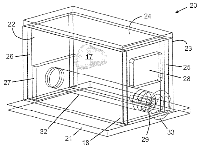
Box-like phantom enclosure 20 comprises base 21, sides 22,23, removable lid
24,
removable front plate 25, and removable back plate 26. The base, sides, lid,
front plate
and back plate are made of transparent polycarbonate. Front plate 25 comprises
rectangular window 28 and cylindrical opening 29, the front plate being
securable to the
sides, base and lid by screws. Rectangular window 28 provides an opening
through
which a brachytherapy needle may be inserted through the skin tissue phantom.
Cylindrical opening 29 provides a simulated rectum through which a TRUS probe
may be
inserted into a cylindrical cavity which provides a simulated lower intestine.
Rod 32 may
be inserted through cylindrical opening 29 into the cylindrical cavity when
the fully
16
CA 02675217 2009-08-11
*assembled phantom is not in use to reduce drying out of the perineal tissue
phantom.
Rod 32 is also used to define the cylindrical cavity while pouring the
perinea, tissue
phantom during initial assembly of the phantom. Cover 34, made of transparent
polycarbonate and used during storage of the fully assembled phantom, may be
secured
to front plate 25 by screws. Rod 32 is equipped with removable knob 33 for
securing the
rod to cover 34 for ease of insertion and withdrawal of the rod from the fully
assembled
phantom. Back plate 26 is securable to the base and lid by screws. Sitting on
the base
at the bottom of the enclosure and in front of back plate 26 is block 27
having a cylindrical
cut-out for accommodating rod 32 and the cylindrical cavity. Lid 24 is
securable to the top
edges of the sides, back plate and front plate by means of screws. Two small
holes in
the base and two small holes in the lid are provided for accommodating two
wires for use
in positioning prostate tissue phantom 17 in the enclosure.
In some embodiments, gaskets may be used to provide air-tight seals at
interfaces
between the sides, front plate, back plate and lid. Further, a fixture for a
seed placement
template may be attached to front plate 25 using holes in the front plate to
which cover 34
is normally screwed during storage. A spacer may be inserted between the
template and
the front plate to maintain a gap between the two.
To initially assemble the various components into a fully assembled phantom,
lid
24, front plate 25 and back plate 26 of enclosure 20 are initially separated
from the empty
enclosure. Rod 32 is inserted into cylindrical opening 29 of front plate 25
and partially
into the empty enclosure. Skin tissue phantom 18 from Example 2 is positioned
so that
rod 32 passes through the circular opening and the skin tissue phantom rests
against the
inside of front plate 25. Rod 32 is then fully inserted into the enclosure so
that the end of
rod 32 rests in the cylindrical cut-out in block 27. A removable window insert
may be
placed in rectangular window 28 to prevent bulging of skin tissue phantom 18
after the
perineal tissue phantom is poured into the enclosure. Alternatively, the skin
tissue
phantom may be cut to fit within the rectangular window, positioned within the
window
and fine wires inserted through small holes in the sides at the front to
prevent the skin
tissue phantom form moving/floating during pouring of the PVA solution for the
perinea!
tissue phantom. In this case, the window insert would be omitted. The front
plate is then
secured with screws.
To ensure that skin tissue 18 phantom adheres to front plate 25, the skin
tissue
phantom is lifted from the front plate and a small amount of PVA or silicone
is spread over
the inside surface of the front plate using a small stir-rod and the skin
tissue phantom is
pressed back down onto the front plate to ensure good contact and smoothed to
remove
17
CA 02675217 2009-08-11
' air bubbles. If necessary, the skin tissue phantom can be carefully lifted
and a thin wire
used to remove any larger air bubbles that may have formed.
To position prostate tissue phantom 17 (prepared in accordance with Example 4
including the urethra tissue phantom) in enclosure 20, two small calibre wires
are partially
inserted into capillary tubes. Using the capillary tubes as needles, the wires
are inserted
through the bottom side of the prostate tissue phantom, one on either side,
approximately
5 mm in from the widest portions, and the capillary tubes are removed. The
ends of the
wires are inserted into the small holes in base 21 (note: smaller end of
prostate tissue
phantom is oriented towards the front), lid 22 is positioned on the enclosure,
and the two
wires are passed through the holes in the lid. The lid is secured with screws.
The wires
are pulled snug from both ends, thereby positioning the prostate tissue
phantom. The
ends of the wires are bent over and taped to the top and bottom of the
enclosure to
maintain the position of the prostate tissue phantom.
The enclosure is then positioned on its front face by placing it on an open
container of just the right size to support the corners of the enclosure. Warm
PVA
solution (less than 55 C) prepared in accordance with Example 5 is then poured
through
the open back face of the enclosure until the level is approximately 5 mm
below the
opening. If the enclosure were to be in its normal orientation, and the
pouring performed
through the top, the prostate tissue phantom could undesirably slide down the
wires. If
the warm PVA solution has a temperature greater than 55 C, the prostate,
urethra and
skin tissue phantoms might melt. Back plate 26 is then replaced and secured
with
screws. The enclosure is returned to its upright orientation to allow the
surrounding warm
PVA to reposition itself. The wires securing the prostate tissue phantom are
not
removed. The warm PVA solution is allowed to cool for at least 2 hours.
One freeze-thaw cycle is then performed to create PVA-C perineal tissue
phantom
in the enclosure surrounding prostate tissue phantom 17. The freeze-thaw cycle
is
performed in a heated/refrigerated circulator bath (VWR model 1187P) or an
Environmental Chamber (Cincinnati Sub-Zero model ZH-8-1-H/AC). The temperature
is
cycled between +20 C and -20 C at controlled cooling and thawing rates
(typically
0.1 C/min), with 1 hour hold periods at -20 C and +20 C. After the freeze-thaw
cycle, the
two wires positioning the prostate tissue phantom are removed. Cover 34 and
knob 33
are secured to front plate 25 and rod 32, respectively, for storage. The cover
together
with the rod are removed when the phantom is in use leaving a cylindrical
cavity in the
perineal tissue phantom for insertion of the TRUS ultrasound.
18
_
CA 02675217 2009-08-11
In the phantom for prostate cancer brachytherapy, the skin and urethra tissue
phantoms undergo seven freeze-thaw cycles in total, the prostate tissue
phantom
undergoes four freeze-thaw cycles in total, and the perineal tissue phantom
undergoes
one freeze-thaw cycle in total.
Example 7: Needle Penetration Properties
A phantom for prostate cancer brachytherapy constructed in accordance with the
examples above has mechanical properties that are suitably within the range of
real-life
biological variation for the prostate gland and surrounding tissues. The most
important
mechanical property from the standpoint of brachytherapy phantoms is the
resistance of
the tissue phantom to needle penetration. Analysis of the needle penetration
forces for
various tissues in real-life prostate cancer brachytherapy operations provides
a range of
forces and an average peak force for each tissue type as shown in Table 2.
Comparison
of these forces to needle penetration forces obtained for various PVA-C
formulations
shows that the formulations for each of the tissue phantoms of the present
invention falls
within the real-life biological variation. Needle penetration forces may be
measured using
any suitable apparatus and method known in the art. A particularly suitable
apparatus is
described in Example 9 below.
For the real tissue samples, the needle penetration forces in Table 2 are the
average maximum force standard deviation. The range of average maximum
needle
penetration forces over five patients is provided in parentheses. The average
maximum
needle penetration force for each patient was calculated from multiple needle
insertions.
For each of the PVA-C samples, the needle penetration forces in Table 2 are
the average
maximum force taken from three needle insertions. The number in front of the
"C" refers
to the number of freeze-thaw cycles, e.g. 15% PVA-1C is a 15% w/w PVA cryogel
having
undergone one freeze-thaw cycle as described previously.
Based on Table 2, it is apparent that the PVA-C formulations described for the
tissue phantoms in the examples above fall within the biological range for
each of the real
tissue types. Thus, the prostate tissue phantom having undergone four freeze-
thaw
cycles (4C) and comprising 15% w/w PVA, 9% w/w Sigmacell, 6% w/w castor oil
and
0.2% w/w Germall Plus would have a maximum needle penetration force at about
4.5 N,
a value close to the middle between 3.0 N and 5.6 N. The perineal tissue
phantom
having undergone one freeze-thaw cycle (1C) and comprising 15% w/w PVA, 3% w/w
Sigmacell, 6% w/w castor oil and 0.2% w/w Germall Plus would have a maximum
needle
penetration force of about 3.0 N. The skin tissue phantom having undergone
seven
19
CA 02675217 2009-08-11
'freeze-thaw cycles (7C) and comprising 20% w/w PVA and 0.2% w/w Germall Plus
would
have a maximum needle penetration force of about 6.3 N for a solid sample. It
is further
evident from Table 2 that a reduction in PVA concentration reduces needle
penetration
force. The addition of castor oil decreases needle penetration force for
samples
containing 15% w/w PVA more significantly than for samples containing 10% w/w
PVA.
Table 2 - Needle Penetration Forces for Real Tissues and Tissue Phantoms
Sample Needle Penetration Force
(N)
Real skin tissue 3.5 1.0 (2.3-5.2)
Real perinea! tissue 2.6 0.6 (1.6-3.3)
Real prostate gland 4.2 1.0 (2.8-5.0)
15% PVA-1C + 0.2% Germall Plus 4.7
15% PVA-6C + 0.2% Germall Plus 8.4
15% PVA-1C + 2% Sigmacell + 0.2% Germall Plus 4.9
15% PVA-6C + 2% Sigmacell + 0.2% Germall Plus 7.7
15% PVA-1C + 6% mineral oil + 0.2% Germall Plus 3.2
15% PVA-6C + 6% mineral oil + 0.2% Germall Plus 6.2
15% PVA-1C + 6% castor oil + 0.2% Germall Plus 3.0
15% PVA-6C + 6% castor oil + 0.2% Germall Plus 5.6
10% PVA-1C + 0.2% Germall Plus 3.7
10% PVA-6C + 0.2% Germall Plus 5.9
10% PVA-1C + 3 % Sigmacell + 6% castor oil + 0.2%
3.2
Germall Plus
10% PVA-6C + 0.5 % Sigmacell + 6% castor oil +
5.4
0.2% Germall Plus
5% PVA-1C + 0.2% Germall Plus 0.8
5% PVA-6C + 0.2% Germall Plus 4.2
5% PVA-1C + 3 % Sigmacell + 6% castor oil + 0.2%
0.9
Germall Plus
5% PVA-6C + 0.5 % Sigmacell + 6% castor oil +
2.3
0.2% Germall Plus
It is interesting to note that a recent publication by Podder et al. [50]
presents a
table with "Max. Force in Perineum (N)" and Max. Force in Prostate (N)". The
forces
reported therein are 15.03 3.26 and 7.11 1.92, respectively, and it is not
clear why the
forces reported by Podder et al. differ from the forces reported herein in
Table 2 for real
tissues.
CA 02675217 2009-08-11
Referring to Fig. 4, Fig. 4A illustrates penetration forces versus depth of 6
needle
insertions for a patient undergoing prostate cancer brachytherapy (finger
direction may
have been used during some of the needle insertions). For comparison, Fig. 4B
illustrates the penetration force versus depth of a needle insertion into the
phantom for
prostate cancer brachytherapy of the present invention (without finger
direction)
performed by the same medical specialist who performed the insertions for Fig.
4A. It is
evident that penetration forces in the phantom of the present invention
reasonably mimic
the forces in real prostate cancer brachytherapy procedures.
Individual insertions by clinicians show a variety of force/depth profiles.
During
needle insertion there are a combination of affects occurring that includes
cutting, sliding,
coulomb friction, tissue deformation and displacement and peeling. In most
cases (but
not all) there is an initial peak within the first 20 mm that coincides with
penetration
through the skin. The force then decreases as the needle penetrates through
the
perineum. Penetration into the prostate is usually evident by a rise in the
force but often
there is little difference between the perineum and prostate forces. Others
have
commented that the frictional forces created on the needle by bursting
strength of the skin
and elasticity of the skin (porcine) resulting in subsequent frictional forces
due to tissue
clamping of the needle cause deviations in the force data.
Within each subject the forces for skin, perineum and prostate insertion can
vary
by a factor of 2. Others have observed a similar variation (90%) related to
peak forces.
Although it was expected that there would be an apparent force increase when
the needle
enters the prostate, it is often difficult to distinguish between penetration
through the
perineum and penetration into the prostate. Through clinical observations and
the
present prostate tissue-mimicking phantom studies it is known that the
prostate moves
(translation, rotation) when the brachytherapy needle enters which contribute
to the
uncertainty. In addition, only the first needle insertion would penetrate
intact tissue.
Subsequent withdrawals/insertions may follow a previous insertion track or
penetrate
intact tissue. If a subsequent insertion force is less, it can be assumed that
the needle
may have followed the previous insertion track. Re-positionings in the
prostate were
usually a deeper penetration into intact tissue but often the forces were less
than the
previous insertion through the prostate. This reduction may be attributable to
a pause to
check ultrasound images to track needle position, which resulted in relaxation
of the
tissue.
As mentioned previously, another factor for the variation in forces for
multiple
insertions along the same track, is "finger direction", where the clinician
reaches behind
21
CA 02675217 2009-08-11
the template to press the needle in a desired direction. In this case it would
be expected
that the forces during subsequent insertions would result in an increase in
the force/depth
plot due to the increased frictional resistance against the surgical glove.
However, a
study of finger direction using tissue-mimicking prostate phantoms showed no
statistically
significant increase for finger direction.
Only the first insertion is not affected by previous insertions and finger
direction.
Most clinicians make the first insertion through the skin and perineum,
stopping when
they penetrate the prostate.
Others have suggested that stiffness of cancerous prostate tissue increases
with
respect to normal prostate tissue. The fact that there is a significant
difference in the
forces for needle penetration into/through the prostate could be interpreted
as
confirmation. However, there are no comparative data for normal prostates
alone. There
are differences in the penetration forces among subjects. The differences,
particularly
"peak", suggest that the biological variation would make it very difficult to
differentiate
cancerous versus normal in a population, using needle penetration as an
indicator of
tissue stiffness.
Consistency of insertion velocity could also be a factor that affects the
force of
penetration. Past measurements of force versus displacement at 3 different
needle
velocities (50 mm/min, 100 mm/min, 150 mm/min) showed a similar force profile
but
lowered peak forces (about 15% for each increment of velocity) through porcine
ligamentum flavum with increased velocity Sample velocities during needle
penetration
were computed, plotted and visually examined for selected tracks. No
consistent trends
between needle force and velocity were evident.
Example 8: Ultrasound Imaging Properties
Ultrasonic sound waves are at frequencies above the audible range (20 kHz).
Although ultrasound exhibits the same physical properties as audible sound
waves, they
are preferred in situations for the following reasons: easily focused (i.e.
directional, beam
can be obtained with very little spreading); inaudible; high frequencies with
shorter
wavelengths allow investigation of very small structure (wavelength should be
of the
same order as the dimensions of the object); and, information obtained by
ultrasound,
particularly dynamic studies, cannot be acquired by any other convenient
technique.
Transmission of ultrasound can be longitudinal, transverse or shear. For
medical
diagnostic applications, the longitudinal mode of wave propagation is normally
used,
22
CA 02675217 2009-08-11
since these waves propagate in all types of media (i.e. solids, liquids,
gases). In
longitudinal waves, the particles of the transmission medium oscillate away
and towards
the direction of propagation of the wave, resulting in alternate regions of
compression and
rarefaction.
The characteristic acoustic impedance determines the degree of reflection at
the
interface between two media. The approximate value of acoustic impedance of
biological
tissues is about 1.6 x 10⁵ g/cm2 s. The greater the difference in acoustic
impedance the
greater is the amount of reflected energy. For example the acoustic impedance
of air
and tissue are about 42.8 g/cm2 s and 1.6 x 10⁵ g/cm2 s, respectively. Since
this
difference is so large most of the ultrasonic energy is reflected at the
interface. Therefore
a coupling agent/medium (e.g. olive oil, special cream) is required to
minimize the energy
reflection by providing an air-free path between the ultrasonic transducer and
the tissue.
The impedance varies over a range of 60 dB. Small changes in the impedance
which are
associated with soft tissue interfaces (as low as 1 ppm) are readily detected,
resulting in
excellent contrast sensitivity.
Echogenicity is one ultrasound imaging property that is important for
mimicking
real tissue in procedures using TRUS imaging. Echogenicity is the ability to
create an
echo, i.e. return a signal in ultrasound examinations. Echogenicity is
important for
creating contrast between different tissues.
Differences in echogenicity between
neighbouring tissues gives rise to the contrast necessary to differentiate
between the
tissues during a TRUS procedure. Echogenicity in a tissue phantom can be
modified with
the use of acoustic scattering particles, and, in the present invention,
differences in
echogenicity between neighbouring tissues has been successfully mimicked by
using
different amounts of acoustic scattering particles in neighbouring tissue
phantoms.
Speed of propagation is a second ultrasound imaging property that is important
for
mimicking real tissue in procedures using TRUS imaging. Ultrasonic frequencies
employed for medical applications range from 1 to 15 MHz. Ultrasonic energy is
transmitted through a medium as a wave motion which does not create any net
movement of the medium and the velocity of propagation of the wave motion is
determined by the density and stiffness of the transmission medium. At a
given
temperature the density and stiffness of a tissue medium are relatively
constant, which
results in a constant sound velocity. Table 3 provides typical values of speed
of
propagation in tissues.
23
CA 02675217 2009-08-11
Table 3 ¨ Properties of Ultrasound in Human Tissues [7]
Material Speed of sound Impedance Attenuation at 1 MHz
(m/s) (kg m-2 s x 10-6) (dB cm-1)
Air (20 C) 343 4 x 10 -4 12.0
Water 1480 1.48 0.002
Fat 1450 1.38 0.6
Brain 1541 1.58 0.85
Liver 1549 1.65 0.9
Kidney 1561 1.62 1.0
Blood 1570 1.61 0.2
Muscle 1585 1.7 2.3
Skull-bone 4080 7.8 13.0
Lens of eye 1620 1.84 2.0
Human soft 1540 1.63 0.8
tissue (average)
Arterial tissue [5] 1501-1532 6-15 (10 MHz)
Arterial [6] 1579-1628 40 (30 MHz)
Attenuation, which is the absorption of an ultrasound beam while passing
through
a medium, is a third ultrasound imaging property that is important for
mimicking real
tissue in procedures using TRUS imaging. Attenuation can be attributed to
adsorption of
the ultrasound beam by the medium and its deviation from the parallel by
reflection,
refraction, scattering, diffraction, etc. Relative intensity and attenuation
of the ultrasound
is expressed in decibels (dB), and the absorption coefficient, a, is expressed
in dB/cm. In
soft tissues a depends strongly on frequency. Therefore, for the same energy
loss, lower
frequency ultrasound would travel further than higher frequency
ultrasound. Table 3
provides listings of typical values of characteristic impedance and
attenuation for various
tissues. The average value of attenuation in soft tissues is about 1
dB/cm/MHz. In
almost all cases, attenuation is approximately proportional to ultrasound
frequency [4].
Table 4 provides a comparison of characteristics in human and canine prostate
tissues.
Table 4 - Ultrasound Properties of Humans and Canine Prostate Tissue
Human [6,7] Canine [11]
Speed of sound (m/s) 1561 22 1558 17
Attenuation (dB/cm-MHz) 0.78 0.24 0.84 0.12
24
CA 02675217 2009-08-11
Table 5 provides speed of propagation data for a 7.5 MHz ultrasound beam in
15% w/w and 20% w/w PVA-C formulations having undergone 1, 3 and 6 freeze-thaw
cycles (FTC). It is evident from comparing Table 5 with Tables 3 and 4 that
the speed of
propagation of ultrasound waves in PVA-C formulations matches well with the
speed of
propagation in, prostate and other soft tissues.
Table 5 ¨ Speed of Propagation of Ultrasound in PVA Cryogels
Composition Speed of Sound (m/s)
1 FTC 3 FTC 6 FTC
15% w/w PVA 1500.29 3.95 1512.17 2.19 1537.85
18.87
20% w/w PVA 1539.12 5.85 1531.49 3.7 1586.31
2.14
Referring to Fig. 5, a TRUS image of the prostate gland during prostate cancer
brachytherapy is shown in Fig. 5A, while a TRUS image of the prostate tissue
phantom of
the present invention set in the perineal tissue phantom of the present
invention is
illustrated in Fig. 5B.
Thus, a phantom for prostate cancer brachytherapy constructed in accordance
with the examples above has speeds of ultrasound propagation that are suitably
within
the range of real-life biological variation for the prostate gland and
surrounding tissues,
and has sufficient differences in echogenicity between neighbouring tissues to
provide the
ultrasound image contrast needed for TRUS.
Example 9: Needle Insertion Force and Track (NIFT) Measurement System with
Needle
Attachment Fixture (NAF)
A particular suitable apparatus is depicted in Figs. 6-9 for measuring needle
penetration properties as discussed in Example 7. In order to measure the
forces with
respect to depth of needle penetration, an apparatus was created that is
suitable for use
in patient cares areas (operating room) of hospitals. The Needle Insertion
Force and
Track (NIFT) measurement system simultaneously measures the needle penetration
forces and needle position to represent a track of needle force versus depth
into the
body. A special needle attachment fixture (NAF) was designed and constructed
that
contained a load cell to measure force and a sensor for a magnetic tracking
system
(Aurora made by Northern Digital Inc.). The NAF attaches to the Luer-LokTm
connector on
the hub of the standard brachytherapy needle. Calibrations and data integrity
assessments were conducted periodically before cases.
CA 02675217 2009-08-11
With reference to Figs. 6-9, components of the NAF include: enclosure 101
comprising housing 102 and front face plate 103; internal slider 105
comprising annular
disk 106 and two rods 107a,107b; needle connector 109, position sensor 111;
and, load
cell 113. Needle connector 109 having LuerLokTM threads therein is bonded to
annular
disk 106 that slides on two rods 107a,107b. The annular disk moves within
housing 102
until it contacts the tip of load cell 113. This mechanism transfers the force
of needle
penetration to the load cell for measurement of axial force (along the axis of
the brachy
needle). Enclosure 101 comprises two parts, housing 102 and front face plate
103
attached by a common screw thread, with a common slot 104. The slot
accommodates
stylette 126 that accompanies the needle when the stylette is partially
withdrawn. Load
cell 113 is mounted in a recess machined in a rear portion of enclosure 101
and held in
place by a cover tab 115. A MagTraxTm screw (position sensor) 111 is threaded
into a rod
attached to a rear of enclosure 101. Holes in the front face plate and housing
fix the ends
of rods 107a,107b. When brachy needle 125 is inserted into a tissue, the
needle hub
transfers the force to connector 109 and annular disk 106 that slides on rods
107a,107b
to contact load cell 113. Any needle with a Luer-LokTM thread can be connected
to the
NAF and still function properly. The diameter of housing 102 depends on the
diameter of
force sensor. Force sensor 113 is offset from the central axis of brachy
needle to
accommodate stylette 126 inserted into the bore of the brachy needle and
retracted from
the hub. Cables from load cell 113 and position sensor 111 are wrapped in a
plastic
spiral wrap 121 to maintain control of the cables. The wrapping prevents
tangling of the
cables which would cause a serious problem or delay during set-up in the
operating
room. The position sensor cable terminates in a simple joiner 127 for
attachment to a
mating joiner outside the surgical field (lying on the floor). A load cell
cable joiner 129
connects directly to a preamplifier at the joiner which provides power to the
load cell,
amplifies the sensor output, and converts the output to a voltage value. The
distal end of
the load cell joiner interfaces with an analogue to digital converter for
input to a computer,
which synchronizes the force with the position. In order to properly
synchronize force and
position, the track of the needle is accurately calculated by known methods.
Advantageously, the NAF of the present invention permits simultaneous sensing
of force
and position, attaches to standard needles with a Luer-Lokp thread on the hub,
permits
transfer of force from the needle to the force sensor, withstands
sterilization by ETO and
cleaning with most antiseptics, is compatible with commercial brachytherapy
needles
without requiring modification, is straightforward to attach/remove to/from
the needle by
the medical specialist, and accommodates normal insertion of the needle
(straight, bi-
directional, rapid pulsing) into the patient.
26
CA 02675217 2015-11-10
In operation, the NIFT is set-up prior to the start of the brachytherapy
procedure.
The NAF is sterilized prior to each case. For each instrumented needle the
urologist inserts
the hub of the brachytherapy needle into the NAF and latches the needle into
place. The
urologist holds only the NAF while inserting the brachytherapy needle through
the template
into the patient. The operator of the NIFT initiates recording when the
urologist has
connected the needle into the NAF. The NIFT records both the force and
position at the
hub of the brachytherapy needle. Although the needle may bend during
insertion, there
remains a fixed distance between the hub and the tip of the needle.
References: The contents of each of which are presumed to be understood by
those
of ordinary skill in the art.
1. Merrick GS, Butler WM, Lief JH, Dorsey AT. Is brachytherapy comparable with
radical
prostatectomy and external-beam radiation for clinically localized prostate
cancer? Tech
UroL 2001 Mar; 7(1):12-9. Review.
2. Blasko JC, Mate T, Sylvester JE, Grimm PD, Cavanagh W. Brachytherapy for
carcinoma
of the prostate: techniques, patient selection, and clinical outcomes. Semin
Radiat
Oncol 2002 Jan; 12(1):81-94. Review.
3. Chivers and Hill, Ultrasound in Med and Biology, 2:25 (1975).
4. Greenleaf J, Duck F, Sabayon W, Johnson S. Ultrasonic data acquisition and
processing system for atherosclerotic tissue characterization. Proc. 1074
Ultrasonic
Sump, pp 738-743 (1974).
5. Lockwood G, Ryan L, Hunt J, Foster F. Measurement of the ultrasonic
properties of
vascular tissues and blood from 35-65 MHz. Ultrasound Med Boil 17, 653-666
(1991).
6. Khandpur AS, Biomedical Instrumentation Technology and Applications, McGraw-
Hill,
2005.
7. Parker,K, Huang S, Lerner R, Lee Jr F, Rubens D, Roach D. Elastic and
Ultrasound
Properties of the prostate. Ultrasonics Symposium (IEEE), 1993, pp 1035-1038.
27
CA 02675217 2015-11-10
8. Paliwal BR, Ritter MA, McNutt TR, Mackie TR, Thomadsen BR, Purdy JA,
Kinsella TJ. A
solid water pelvic and prostate phantom for imaging, volume rendering,
treatment
planning, and dosimetry for an RTOG multi-institutional, 3-D dose escalation
study. mt.
J. Radiat. OncoL BioL Phys. 1998 Aug 1; 42(1):205-11.
9. Holmes III D, Davis B, Bruce C, Wilson T, Robb R. Trans-urethral ultrasound
imaging of
the prostate for applications in prostate brachytherapy: Analysis of phantom
and in vivo
data. Proceedings of SPIE The International Society for Optical Engineering. v
4319,
2001 p 46-52.
10. Radford DA, Followill DS, Hanson WF. Design of an anthropomorphic
intensity
modulated radiation therapy quality assurance phantom. 22nd Annual
International
Conference of the IEEE Engineering in Medicine and Biology Society. Chicago,
USA.
11. Chu KC, Rutt BK. Polyvinyl alcohol cryogel: an ideal phantom material for
MR studies of
arterial flow and elasticity. Magn. Reson. Med. 1997 Feb; 37(2):314-9.
12. Mitchell MD, Kundel HL, Axel L, Joseph PM. Agarose as a tissue equivalent
phantom
material for NMR imaging. Magn. Reson. Imaging. 1986; 4(3):263-6.
13. Madsen EL, Frank GR, Dong F. Liquid or solid ultrasonically tissue-
mimicking materials
with very low scatter Ultrasound. Med. Biol. 1998 May; 24(4):535-4.
14. Peppas NA. Biomaterials Science: An Introduction to Materials in Medicine.
Ratner BD,
Hoffman AS, Schoen FJ, Lemons JE. eds. Academic Press Inc Toronto 1996:62.
15. Ratner BD, Hoffman AS. Synthetic Hydrogels for Biomedical Applications, in
Hydrogels
for Medical and Related Applications, Andrade JD, ACS Symposium Series,
American
Chemical Society, Washington; 1985; 31:14.
16. Bray JC, Marty EW. PVA hydrogel for synthetic articular cartilage
material. J. Biomed
Mater Res. 1973; 7:431.
17. Watase M, Nishinari K, Nambu M. Anomalous Increase of the Elastic Modulus
of Frozen
Poly (Vinyl Alcohol) gels. Cryo-Letters. Cambridge, Mass 1983; 4:197-200.
28
CA 02675217 2015-11-10
21. Peppas NA, Stauffer SR. Reinforced uncrosslinked poly (vinyl alcohol) gels
produced by
cyclic freezing-thawing processes: a short review. Journal of Controlled
Release 1991;
16:305-310.
22. Stauffer SR, Peppas NA. Poly (vinyl alcohol) hydrogels prepared by
freezing-thawing
cyclic processing. Polymer 1992; 33:3932-3936.
23. Wan W, Campbell G, Zhang Z, Hui A, Boughner D. Optimizing the Tensile
Properties of
Polyvinyl Alcohol Hydrogel by the Freeze-Thaw Process for Bioprosthetic Heart
Valve
Stent. J. Biomed. Mater. Res .(Applied Biomater). 2002; 63:854-861.
24. Campbell G, Wan W. The Synthesis of Polyvinyl Alcohol Cryogel as an
Implant
Biomaterial. Proceedings of 2002 NRC-NSC Canada-Taiwan Joint Workshop on
Advanced Manufacturing Technologies, Sept. 2002, pgs. 137-144.
25. Berry E, Brown JM, Connell M, Craven CM, Efford ND, Radjenovic A, Smith
MA.
Preliminary experience with medical applications of rapid prototyping by
selective laser
sintering. Med Eng Phys. 1997 Jan; 19(1):90-6.
26. Aung SC, Tan BK, Foo CL, Lee ST. Selective laser sintering: application of
a rapid
prototyping method in cranio-maxillofacial reconstructive surgery. Ann Acad
Med
Singapore. 1999 Sep; 28(5):739-43.
27. Berry E, Marsden A, Dalgarno KW, Kessel D, Scott DJ. Flexible tubular
replicas of
abdominal aortic aneurysms. Proc lnst Mech Eng [H]. 2002; 216(3):211-4.
28. Khandpur AS. Biomedical Instrumentation (technology and application).
Ultrasonic
Imaging Systems, 2005; pg. 623.
29. AIUM (American institute of ultrasound in medicine). Methods for
Specifying Acoustic
Properties of Tissue Mimicking Phantoms and Objects, 1995.
30. Madsen EL, Zagzebski JA, Banjavie RA, Jutila RE. Tissue Mimicking
Materials for
Ultrasound Phantoms. Med. Phys. Sep./Oct. 1978; 5(5),.
31. Madsen E, Zagzebski J, Banjavic R, Burlew M. Phantom Material and Method.
U.S.
Patent 4,277,367 (Jul 7, 1981).
29
CA 02675217 2009-08-11
133. Madsen E, Zagzebski J, Frank G. Ultrasound Phantom. U.S. Patent 4,843,866
(Jul 4,
1989).
34. Madsen E, Frank G. Very Low Scatter liquid and Solid Tissue Mimicking
Material for
Ultrasound Phantoms and Method of Making the Same. U.S. Patent 5,625,137 (Apr
29, 1997).
35. Madsen E, Frank G. Method of Making a Solid Tissue Mimicking Material for
Ultrasound Phantoms. U.S. Patent 5,902,748 (May 11, 1999).
36. Madsen E, D'Souza W, Frank G. Multi-imaging Modality Tissue Mimicking
Materials
for Imaging Phantoms, U.S. Patent 6,318,146 (Nov 20, 2001).
37. Madsen E, Zagzebski J, Frank G. Multi-imaging Modality Tissue Mimicking
Materials
for Imaging Phantoms. U.S. Patent Publication 2002/0012999 (Jan 31, 2002).
38. Madsen E, Frank G. Liquid and Solid Tissue Mimicking Material for
Ultrasound
Phantoms and Method of Making the Same. U.S. Patent 6,352,860 (Mar 5, 2002).
39. Madsen E, Frank G. Liquid and Solid Tissue Mimicking Material for
Ultrasound
Phantoms and Method of Making the Same. PCT publication WO 02/40985 (May 23,
2002).
40. Madsen E, D'Souza W, Frank G. Multi-imaging Modality Tissue Mimicking
Materials
for Imaging Phantoms. U.S. Patent 6,635,486 (Oct 21, 2003).
41. Madsen E, Frank G. Tissue Mimicking Elastography Phantoms. U.S. Patent
Publication 2004/0067591 (Apr. 8, 2004).
42. Ophir J, Maklad N, Jaeger P. Ultrasound Phantom. U.S. Patent 4,286,455
(Sep. 1,
1981).
43. Gurvich V. Test Phantom for Information Systems and Methods of Use. U.S.
Patent
5,994,900 (Nov 30, 1999).
44. Pagoulatos N, Haynor D, Edwards W, Kim Y. Apparatus and Method for
Interactive
3D Registration of Ultrasound and Magnetic Resonance Images Based on a
Magnetic
Position Sensor. U.S. patent 6,775,404 (Aug 10, 2004).
45. Lopez H, Smith W. Contrast Resolution Tissue Equivalent Ultrasound Test
Object.
U.S. Patent 4,331,021 (May 25, 1982).
_
CA 02675217 2009-08-11
(' 4.46. Flax S. Method for Evaluating Imaging Capabilities of an Ultrasound
System. U.S.
Patent 5,656,763 (Aug 12, 1997).
47. Zerhouni M, Rachedine M. Ultrasonic Calibration Material and Method. US
patent
5,196,343 (Mar 23, 1993).
48. Fromageau J, Gennisson J-L, Schmitt C, Maurice RL, Mongrain R, Cloutier G.
Estimation of Polyvinyl Alcohol Cryogel Mechanical Properties with Four
Ultrasound
Elastography Methods and Comparison with Gold Standard Testing.
IEEE
Transaction on Ultrasonics, Ferroelectrics, and Frequency Control, March 2007,
vol.
54(3), pgs. 498-509.
49. Hassan CA, Peppas MA. Structure and Applications of poly (vinyl alcohol)
hydrogels
produced by conventional cross-linking or by freezing/thawing methods. Adv.
Polymer Sci. 2000, vol. 153, pgs 37-65.
50. Podder T, Sherman J, Clark D, Messing E, Rubens, Strang, Liao L,
Brasacchio,
Zhang Y, Ng W, Yu Y. Evaluation of robotic needle insertion in conjunction
with in vivo
manual insertion in the operating room. IEEE International Workshop on Robots
and
Human Interactive Communication. 2005, pp 66-72.
Other advantages that are inherent to the structure are obvious to one skilled
in
the art. The embodiments are described herein illustratively and are not meant
to limit
the scope of the invention as claimed. Variations of the foregoing embodiments
will be
evident to a person of ordinary skill and are intended by the invent& to be
encompassed
by the following claims.
31