Note: Descriptions are shown in the official language in which they were submitted.
CA 02675327 2009-07-13
WO 2008/089085 PCT/US2008/050897
-1-
GRAPHITE-MEDIATED CONTROL OF STATIC ELECTRICITY ON
FIBERGLASS
CROSS REFERENCE TO RELATED APPLICATION
This application claims the benefit of U.S. Provisional Application No.
60/884,716, filed January 12, 2007.
TECHNICAL FIELD
The present invention relates to a fiberglass material and a method for
producing the same, particularly a fiberglass material that is substantially
free of static
electricity.
BACKGROUND
Fiberglass is used in a variety of thermal insulation applications
including, for example, in building insulation, pipe insulation, and in molded
automobile parts (e.g., hood liners), as well as in a variety of acoustical
insulation
applications including, for example, in molded automobile parts (e.g.,
dashboard
liners) and office furniture/panel parts. A general discussion of fiberglass
manufacturing and technology is contained in Fiberglass by J. Gilbert Mohr and
William P. Rowe, Van Nostrand Reinhold Company, New York 1978, the disclosure
of which is hereby incorporated herein by reference.
Certain fiberglass insulation products include matted glass fibers that
are bound or held together by a cured, water-resistant thermoset binder.
During
production of such products, streams of molten glass are drawn into fibers of
varying
lengths and then blown into a forming chamber where they are deposited with
little
organization, or in varying patterns, as a mat onto a traveling conveyor. The
fibers,
while in transit in the forming chamber and while still hot from the drawing
operation,
are sprayed with an aqueous binder solution. In addition to binders, an anti-
static
composition, typically consisting of a material that minimizes the generation
of static
electricity and a material that serves as a corrosion inhibitor and a
stabilizer, may also
be sprayed onto the surface of glass fiber mats. The residual heat from the
glass
fibers and the flow of cooling air through the fibrous mat during the forming
operation generally evaporates most of the water from the binder and any anti-
static
CA 02675327 2009-07-13
WO 2008/089085 PCT/US2008/050897
-2-
composition, and causes the binder and anti-static agent to penetrate the
entire
thickness of the mat. Subsequently, the coated fibrous mat is transferred out
of the
forming chamber to a transfer zone where the mat vertically expands due to the
resiliency of the glass fibers. The coated mat is then transferred to a curing
oven,
where heated air is blown through the mat, or to a curing mold, where heat may
be
applied under pressure, to cure the binder and rigidly attach the glass fibers
together
for use in various types of cured fiberglass insulation products (e.g.,
building
insulation, molded automobile hood liners, and office furniture/panel parts).
Other types of fiberglass insulation products include glass fibers that
are not bound or held together by a cured binder. During production of such
products,
streams of molten glass are drawn into fibers of varying lengths and then
blown into a
forming chamber where they are deposited with little organization, or in
varying
patterns, as a mat onto a traveling conveyor. Subsequently, the fibrous mat is
transferred out of the forming chamber to a transfer zone where the mat
vertically
expands due to the resiliency of the glass fibers. The expanded glass fiber
mat is then
sent through a mill, e.g., a hammermill, to be cut apart, after which
treatment various
types of fluids, including oil, silicone, and/or anti-static compounds, may be
applied.
The resulting glass fibers, commonly known as "loose-fill" fiberglass, are
collected
and compressed into a bag for use in various types of uncured fiberglass
insulation
products (e.g., attic insulation).
Despite the use of one or more anti-static agents, static electricity, in
the form of a static charge, may build up on the surface of individual glass
fibers in
fiberglass insulation products, such as the afore-mentioned cured fiberglass
insulation
products and loose-fill fiberglass.
Static electricity, which is a function of mechanical motion,
atmospheric conditions, and/or location in an electric field, may cause end
product
loss and/or downtime in manufacturing and commercial applications involving
fiberglass, and can be hazardous in explosive environments. For example,
static
electrical charge accumulated during manufacturing of cured fiberglass
insulation
may lead to an unwanted accumulation of dust on an insulation product, by
virtue of
dust being attracted to a statically-charged surface. Such accumulated dust
may have
to be removed in order for the insulation product to be within a desired dust
specification. Further, during the commercial installation of uncured loose-
fill
CA 02675327 2009-07-13
WO 2008/089085 PCT/US2008/050897
-3-
fiberglass insulation, glass fibers blown through several hundred feet of
plastic (e.g.,
polyethylene) tubing several inches in diameter experience high-speed
mechanical
motion, and may acquire a static electrical charge as a result. Such
statically-charged
fiberglass may accumulate in undesirable locations, including, for example, on
the
underside of a roof, on rafters, and/or on ductwork, and even on the installer
him- or
herself, often resulting in an unpleasant, but usually not life-threatening
(unless
flammable solvents are present), electrical shock.
Accordingly, compositions and methods for controlling static
electricity build up on glass fibers during the manufacture and installation
of
fiberglass insulation has continued to receive attention.
SUMMARY
The present invention may comprise one or more of the following
features and/or combinations thereof. A fiberglass material contains glass
fibers
having graphite evenly distributed thereon. The graphite acts as an anti-
static coating,
therefore, the fiberglass material described herein is substantially free of
static
electricity. The fiberglass material may have any suitable graphite content,
for
example, about 0.25 wt% to about 0.50 wt% of dry weight of the glass fibers,
or about
0.25 wt% to about 1.0 wt%, or about 0.8 wt%. The graphite used to produce the
fiberglass material may be synthetic or natural graphite, having carbon
content of
about 90 % to about 100 %. The fiberglass material may also include small
amounts
of other components, for example, silicone, de-dusting oil, dye, or any
combination
thereof. The fiberglass material is particularly suitable for use in thermal
insulation
applications.
In a specific example, the fiberglass material is used as a loose-fill
fiberglass insulation. The fiberglass insulation includes loose-fill
fiberglass and dry
graphite powder distributed throughout the fiberglass. The graphite content of
about
0.25 wt% to about 0.50 wt%, or about 0.25 wt% to about 1.0 wt%, or about 0.8
wt%
of the dry weight of the loose-fill fiberglass is sufficient for the
fiberglass insulation
to be substantially free of static electricity during production and
installation. The
insulation material may also contain de-dusting oil at about 0.1 wt% to about
2.0 wt%
or less.
CA 02675327 2009-07-13
WO 2008/089085 PCT/US2008/050897
-4-
In another aspect, a method for producing a fiberglass material
substantially free of static electricity is described. The method generally
involves
mixing dry graphite with glass fibers so that the graphite is evenly
distributed on the
glass fibers. As above-mentioned, the graphite used may be natural graphite or
synthetic graphite in the form of powder or flakes. The powdered graphite may
have a
particle size of about 1 micron to about 50 microns. The carbon content of the
graphite may be about 90 wt% to about 100 wt%. The graphite may be used at any
suitable rate. For example, the graphite of about 0.25 wt% to about 0.50 wt%,
or
about 0.25 wt% to about 1.0 wt%, or about 0.8 wt% of dry weight of the glass
fibers
may be used. A de-dusting oil may also be added to the glass fibers.
Alternatively, graphite in a fluid form may be used to apply to the
glass fibers to make a fiberglass material substantially free of static
electricity. The
method may start with mixing graphite with a fluid such as water or oil to
form a
dispersion. The dispersion may contain any suitable amount of the graphite.
For
example, a dispersion containing about 3.4 wt% graphite is a suitable graphite
mixture. The rate of application may vary and depend on the desired coverage
of the
graphite. However, as above-mentioned, the resulting fiberglass material
should
contain about 0.25 wt% to about 0.50 wt%, or about 0.25 wt% to about 1.0 wt%,
or
about 0.8 wt% of dry weight of the glass fibers. The dispersion may further
contain a
dispersant or a wetting agent to facilitate wetting of the graphite or a
thickener to
increase the viscosity of the dispersion, or both. After the dispersion is
applied over
the glass fibers, the glass fibers are dried and the graphite residue is left
attached to
the glass fibers.
The method of making the present fiberglass material can be integrated
with the manufacturing process of a loose-fill fiberglass insulation material.
The new
manufacturing process generally includes fiberizing starting glass material
into glass
fibers, chopping or milling the glass fibers into short pieces as chopped
glass fibers,
and packaging the chopped glass fibers in a bag. The process also includes
applying
graphite to either the glass fibers before the chopping step or to the chopped
glass
fibers after the chopping step. It is possible to add graphite to the chopped
glass
fibers at various locations along the transport line up to the packaging step.
In the
manufacturing process, it is possible to apply either dry graphite or graphite
suspension to the glass fibers. Both synthetic and natural graphite may be
used.
CA 02675327 2009-07-13
WO 2008/089085 PCT/US2008/050897
-5-
Graphite powder may be mixed with a fluid such as water or light oil to make a
dispersion for injecting over the glass fibers. Using a fluid dispersion
requires the
glass fibers to be dried. In one application, the graphite dispersion is
applied to the
glass fiber veil at the fiberizer, the heat from the fiberizer will dry the
glass fibers
leaving the graphite attached to the glass fibers. In another application, dry
graphite
powder is added over the chopped glass fibers after they pass through a
hammermill
and being transported in a negative pressured air duct. In another
application, the
graphite dispersion is injected over the chopped glass fibers in an injection
area before
they reach an air/fiber separator. In an alternative application, the dry
graphite
powder is added to the chopped glass fibers right before they are compressed
into a
continuous sheet in an air/fiber separator. In yet another application, dry
graphite
powder is added on to the continuous sheet of glass fibers on a conveyor belt
prior to
entering a bagging operation. The graphite content in the manufactured product
should be about 0.25 wt% to about 0.50 wt%, or about 0.25 wt% to about 1.0
wt%, or
about 0.8 wt% of the glass fibers, using graphite having particle sizes of
about 1
micron to 50 microns. It is contemplated the graphite content may vary due to
the
sizes of the graphite particles used.
It is to be understood that other substances such as including a de-
dusting oil, silicone, a dye or a binder may also be applied to the glass
fibers together
with the graphite powder or the graphite dispersion. The graphite dispersion
may also
include a dispersant, a thickener, or any combination thereof.
Additional features of the present invention will become apparent to
those skilled in the art upon consideration of the following detailed
description of
illustrative embodiments exemplifying the best mode of carrying out the
invention as
presently perceived.
BRIEF DESCRIPTION OF THE DRAWINGS
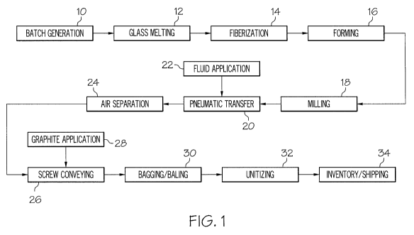
FIG. 1 is a diagram representing an embodiment of a manufacturing
process for making a fiberglass material.
DETAILED DESCRIPTION
Despite the use of traditional anti-static agents, static electricity is
usually built up on the surface of individual glass fibers in fiberglass
insulation
CA 02675327 2009-07-13
WO 2008/089085 PCT/US2008/050897
-6-
products during manufacturing and installation. The fiberglass material
described
herein is substantially free of static electricity. The fiberglass material
contains glass
fibers having graphite attached or coated on the surface thereof.
Depending on the form of the glass fibers, a variety of fiberglass
products may be made from the present fiberglass material. The glass fibers
may be
continuous fibers used in yarns and textile or discontinuous fibers which are
short
pieces of fibers used as batts, blankets or boards for insulation or
infiltration. The
continuous fiberglass yarn may be woven into fabric which may be used as
draperies
or as a reinforcement material for mold and laminated plastics. The
discontinuous
glass fibers may be formed into wool like material that is thick and fluffy
suitable for
use for thermal insulation and sound absorption. The discontinuous glass
fibers is
used to form a loose-fill fiberglass material that is commonly used for home
insulation.
The glass fibers may be made of any suitable raw materials. For
example, the glass fibers may be produced from a variety of natural minerals
or
manufactured chemicals such as silica sand, limestone, and soda ash. Other
ingredients may include calcined alumina, borax, feldspar, nepheline syenite,
magnesite, and kaolin clay. The method of forming fibers (fiberization) from
the raw
glass material is generally known in the art. The fibers once formed, may be
pulverized, cut, chopped or broken into suitable lengths for various
applications.
Several devices and methods are available to produce short pieces of fibers
and are
known in the art.
The graphite used to make the present fiberglass material may be
natural graphite or synthetic graphite. The naturally occurring graphite is
typically
found as discrete flakes ranging in size from 50 to 800 microns in diameter
and 1-50
microns thick. This form of graphite usually exhibits high thermal and
electric
conductivity. Commercial grades are available in purities ranging from 80-
99.9%
carbon, and sizes from 2 to 800 micrometers. The synthetic graphite is made by
high
temperature heat treatment of amorphous carbon materials. The morphology of
most
synthetic graphite varies from flaky in fme powders to irregular grains and
needles in
coarser products. Synthetic graphite is available in particle sizes from 2-
micron
powder to 2 cm pieces. The synthetic graphite has relatively high purity
because the
high processing temperature vaporizes the impurities including metal oxides,
sulfur,
CA 02675327 2009-07-13
WO 2008/089085 PCT/US2008/050897
-7-
and other organic components of the raw materials. Purities are typically 99+%
carbon. It is desirable, for health and safety reasons, that the graphite used
in the
present application is substantially pure and contains no silica. Because the
synthetic
graphite is substantially pure and can be made into uniformly fme powder, the
synthetic graphite is well suited for making the present fiberglass material.
The present fiberglass material may contain a suitable amount of
graphite that allows an even distribution on the surface of the glass fibers.
The size of
the graphite particles will have an effect on the distribution of the
graphite. If the
particles are relatively large, the coverage on the glass fibers may not be as
even as if
the smaller particles are used. Therefore, it may be necessary to increase the
amount
(weight) of the graphite applied to the glass fibers, when the large graphite
particles
are used. It has been discovered that the present fiberglass material should
have a
graphite content of about 0.25 wt% to about 0.50 wt%, or about 0.25 wt% to
about 1.0
wt%, or about 0.8 wt% of dry weight of the glass fibers, provided that the
graphite
particles are about 1 to 50 microns in size.
Although the graphite alone can confer static free characteristics of the
fiberglass material, adding other substances to the fiberglass material may be
beneficial. For example, a de-dusting oil such as Synthospin P10 (Lenox
Chemical
Company) or a suitable process oil may be used to treat the glass fibers to
reduce dust
formation during processing, packaging or installation of the fiberglass
material.
Optionally, a lubricant, silicone or a binder may also be included.
A specific insulation material substantially free of static electricity
contains loose-fill fiberglass and graphite powder distributed on the surface
thereof to
facilitate anti-static property. The graphite treated loose-fill fiberglass
may be bonded
or non-bonded. Bonded loose-fill insulation refers to loose-fill fiberglass
which has
been treated with a thermoset binder to form a blanket or a batt, pulverized,
compressed, and bagged. Non-bonded, loose-fill insulation comprises smaller
short
fibers, compressed and packaged into bags. A typical bag contains about 25-35
lbs of
the insulation material. Both bonded and non-bonded loose fill insulations can
be
installed in attics and sidewalls using a pneumatic blowing machine or a
similar
equipment. The graphite coated loose-fill fiberglass insulation can be easily
installed
within the desired area. The insulation material can be blown to a distant
location and
does not accumulate dust. The material does not generate significant static
electricity
CA 02675327 2009-07-13
WO 2008/089085 PCT/US2008/050897
-8-
that may cause an electrical shock to the installer or may cause clogging up
of the
blowing machine.
A method for producing the fiberglass material substantially free of
static electricity involves mixing graphite with glass fibers so that the
graphite is
evenly distributed on the glass fibers. As previously mentioned, the graphite
used in
the process may be a natural material or synthetic material. It may be pure or
substantially pure having the carbon content of about 80 wt% to about 100 wt%.
Although a purity of more than about 98% is more desirable. The graphite may
be
used in the forms of dry powder, flakes, or suspension. The examples of
commercial
graphite that have been used in the dry application are A99 graphite (Asbury
Graphite
Mills Inc.), which is synthetic powdered graphite, and 230U graphite (Asbury
Graphite Mills Inc.), which is a natural flake type. Both types of graphite
have
particle sizes of about -325 mesh (the mean size of 25 microns, and the
maximum size
of 44 microns).
For a dry application, initial tests were performed using synthetic
graphite powder with an average particle size of 3.3 microns and natural
graphite
flakes having an average size of 188 microns. About 10 grams of the synthetic
graphite or 50 grams of the natural graphite was mixed with a bag of loose-
fill
fiberglass material (28-34 pounds) as it was being fed into a blowing machine
for
installation. It was observed that there was a significant reduction in the
static
electricity generated. There was little to no difficulty in the installation
of the
fiberglass material that is caused by static electricity.
In another dry application experiment, the dry graphite powder was
"salted" on the loose-fill fiberglass at the rates of about 30 and 60 grams
per bag of
fiberglass (28-34 pounds) (LOI, Loss of Ignition, value of about 0.22 % and 0.
44%,
respectively). In addition, a de-dusting oil or Synthospin P10, was optionally
added
at the rate of 0.25% LOI. The graphite used in this experiment was a
synthetic,
powdered graphite at 98% carbon content, having the particle size of about -
325 mesh
(44 microns). This graphite did not contain silica. Several bags of graphite
treated
loose-fill fiberglass were prepared and tested against the baseline material
(no
graphite). The resulting graphite-treated fiberglass products showed a
significant
reduction in static electricity during installation of the loose-fill
fiberglass insulation.
It was observed however that if the air condition is dry during the production
of the
CA 02675327 2009-07-13
WO 2008/089085 PCT/US2008/050897
-9-
fiberglass material, the absence of liquid antistatic may slow down the glass
fibers
running through the bagging operation. This was due to the amount of static
produced by the process which caused the glass to hang up in the weight
hopper, thus
producing light bags and eventually shutting the line down.
The graphite powder or flakes may be first prepared as a dispersion in
oil or water before applying to the glass fibers. Alternatively, commercial
graphite
suspension may also be used. For example, Graphokote 784 (Dixon graphite) a
graphite impregnated in process oil), has been tried. Independent from the
type of
graphite used, the graphite content in the dispersion may be adjusted to a
suitable
level. To facilitate the dispersion of the graphite in the fluid, a dispersant
such as
TAMOL SN (Rohm & Haas Company) or a wetting agent may be added. For
example, a dispersion may be made using A99 or 230U in water, yielding
graphite
content of about 3.4 wt%. The dispersion may be applied to the glass fibers at
a
graphite rate of about 0.25 wt% to about 0.50 wt%, or about 0.25 wt% to about
1.0
wt%, or about 0.8 wt% of dry weight of the glass fibers. A thickener may also
be
added to increase the viscosity of the dispersion. The dry and wet ingredients
may be
mixed in a container or a bag with sufficient agitation to prevent the
graphite particles
from settling at the bottom of the container before use. Small amounts of de-
dusting-
oil and silicone may be added to the dispersion at a rate of 0.1 wt% to 2.0
wt% to
improve the processing and installation quality of the insulation material. If
desired, a
dye may also be added. Alternatively, the de-dusting oil and silicone may be
applied
to the glass fibers separately from the graphite dispersion.
The method of producing substantially static free fiberglass insulation
material is applicable to the manufacturing process of the loose-fill
fiberglass
insulation. Referring now to FIG. 1, a diagram demonstrating a manufacturing
process of a loose-fill fiberglass insulation material is shown. The
manufacturing
process begins with a batch generation 10 in which ingredients for the batch
are
collected and transferred to a glass melting process 12. The melting process
12
consists of mixing and melting the multiple, solid ingredients of the batch.
The
molten glass is then transferred via a network of canals and forehearths
towards the
fiberization process 14.
The fiberization process 14 mainly consists of spinning the molten
glass, via rotary process, into glass fibers. This is done at a controlled
mass rate. The
CA 02675327 2009-07-13
WO 2008/089085 PCT/US2008/050897
-10-
fiberization process is designed such that a targeted fiber diameter and
length is
produced. Typically, this is accomplished by multiple spinning machines, also
known
as fiberizers. The newly formed, virgin glass fibers are then directed toward
the
forming process 16 in which the fibers are captured inside a tower, on a
forming
chain. The forming chain or forming conveyor then transfers a blanket of the
fibers
towards the milling process 18.
The blanket of virgin fibers exiting the forming process 16 enters a
chopping mill of the milling process 18. The purpose of the milling process 18
is to
separate the blanket into smaller clumps as well as to consistently cut the
virgin fibers
to a controlled length. Upon exiting the milling process 18, the fibers are
pneumatically transferred 20 to a separate part of the plant. During the
pneumatic
transfer 20, multiple fluids are applied to the glass. This fluid application
process 22
is done by air atomizing and spraying each fluid into the air stream of the
pneumatic
transfer process 20. Each fluid then coats the glass fibers. The fluids may
protect the
glass fibers from moisture, may knock down smaller, dustier fibers, and may
control
static electricity. The multiple fluids are typically applied at 1.0-1.5%
solids by
weight of glass.
To further process the glass fibers, textile separators may separate the
glass fibers from the pneumatic transfer process using air separation 24. The
air
separation process 24 may result in the separated fibers having a blanket
form.
The newly formed glass fiber blanket, upon exiting the air separation
process 24 is conveyed via a large diameter screw during a screw conveying
process
26. The purpose of the screw conveying process 26 is two-fold. First, the
screw
conveying process 26 is responsible for breaking the blanket formed by the air
separation process 24 into small pieces, without harming the glass fibers.
Second, the
screw conveying process 26 aids the graphite application process 28. The
graphite
application process 28 applies a dry, powdered graphite to the glass fibers
during the
screw conveying process 26. The graphite helps eliminate generation of static
electricity during the installation of the glass fibers such as blowing such
fibers into
an attic for insulation. The graphite used is synthetic (>99.5% carbon),
milled to a
particle size of -325 mesh. This powdered graphite is metered onto the glass,
during
the screw conveying process 28, via a volumetric screw feeder. The speed of
the
volumetric screw feeder is controlled to coincide with the mass of the glass.
In one
CA 02675327 2009-07-13
WO 2008/089085 PCT/US2008/050897
-11-
embodiment, the graphite is applied at 0.5% by weight of glass. Research has
shown
that higher levels of graphite on the glass are more favorable in eliminating
the
generation of static electricity during the final installation process. Thus,
another
embodiment applies the graphite at 0.8% by weight of glass.
Upon exiting the screw conveying process 26 and graphite application
process 28, the glass undergoes a bagging and baling process 30. During the
bagging
and baling process 30, the glass fibers enter machines that compresses 30-32
lbs of
glass into a bale and inserts the compressed glass bale into a bag. Each bale
then
undergoes a material handling process 32 in which the bales are neatly stacked
into
piles or units for storage and shipping.
As shown at 34, the units are now ready to be inventoried in a
warehouse before being shipped to the customer.
Example 1: Water Dispersion Applied at Fiberization Process 14
This experiment involved injecting an atomized water and graphite
dispersion prepared as above-described into the virgin glass fiber veil
immediately
after the fiberization process 14. Both synthetic and natural graphite were
tested, each
at two different graphite levels, 0.25% LOI and 0.50% LOI. As expected, the
heat of
the fiberization process 14 vaporized the water carrier quickly, leaving
behind the
graphite powder on the glass.
The dispersion was prepared in water with approximately 3.4 wt%
graphite. A very small amounts of dispersant was added to help in wetting the
graphite in the water. In addition, a small amount of thickener was added to
increase
the viscosity of the mix and thus slowing the fall out rate. This mix enabled
the
application of graphite at a rate of 0.5wt % of dry weight of glass. The
dispersion was
mixed by hand in clean, empty totes. The dispersion was transferred from a
tote to
the fiberizer deck by pumping through a 1-inch hose. A half inch hose was
branched
off of the 1-inch hose supply line near the MicroMotion that carried excess
dispersion
back down to the tote. The recirculation of the dispersion helped in agitation
and
keeping the dispersion in suspension.
CA 02675327 2009-07-13
WO 2008/089085 PCT/US2008/050897
-12-
Example 2: Dry Powder Applied into Duct Air Stream After the Milling
Process 18.
This process involved injecting a dry, powdered graphite (synthetic, -
325 mesh, 99.7% carbon) into a transport duct of the pneumatic transfer
process 20 at
approximately 10 feet after a Munson Mill of the milling process 18. The
graphite
flow rate of 0.25 wt% of dry weight of glass was applied. This process
employed the
transport duct, that was used to pneumatically convey the glass during the
transfer
process 20, to convey the powdered graphite with it, thereby packaging both
the
graphite and the glass in a bag at the end of the process.
Example 3: Process Oil Dispersion Applied at Fluid Application 22 During
Pneumatic Transfer 20
At this location, a graphite impregnated oil prepared from Graphokote
784 which contains 75 % Paralux process oil and 25% synthetic graphite by
weight,
in suspension was used. The Graphokote at two different levels (0.50 and 1.00%
LOI) was used. Since the Graphokote is actually 25% graphite by weight, this
should
only yield actual graphite LOI's of 0.13 and 0.25%. The graphite dispersion
was
pumped at a controlled flow and atomized as it was injected into the air
stream of the
duct, thereby allowing them to attach to the glass fibers.
Example 4: Dry Powder Applied into Air Duct of Pneumatic Transfer
Process 20 Before Air/Fiber Separation Process 24
At this location, dry powdered synthetic graphite (-325 mesh, 99.7%
carbon) was applied into the air stream at both 0.25 wt % and 0.50 wt % of dry
weight
of the glass. This was similar to the process described in Example 2. The
air/fiber
separator drum, as it separated the glass fibers and air stream, created a
continuous
sheet of glass fibers on the outside of the drum. Applying dry powder here
employed
this continuous sheet to filter the dry powder from the air stream, thus
keeping the
powder on the glass fibers.
Example 5: Dry Powder Applied to Glass Fibers on Conveyer During
Screw Conveying Process 26
At this location, dry powdered, synthetic graphite (-325 mesh, 99.7%
carbon) was "salted" at both 0.25 wt % and 0.50 wt % of dry weight of the
glass on
CA 02675327 2009-07-13
WO 2008/089085 PCT/US2008/050897
-13-
the continuous sheet of glass fibers created by the air/fiber separator drum,
immediately before the glass fibers are bagged for shipping. The dry powder
was
carried along with the glass fibers through the bagging operation where it
ended up
with the glass fibers in the finished, packaged product.
In addition, samples with a very high level of graphite LOI (4%) was
also produced by sprinkling the graphite powder on to the fonning chain
(sheet) of the
glass fiber.
Several bags of fiberglass material were produced in accordance with
the above examples (see Table). It is notable that in conjunction with the two
different
levels of graphite for each set point, the materials were made with and
without
Synthospin P10, always keeping the overall fluids LOI at 1.25%. It was
required that
the de-dusting oil and silicone were to be added in accordance with sans P 10
set
points. In addition, a dye was added to all set points containing Synthospin
P10 to
observe the effect of graphite to the color of certain fiberglass products.
CA 02675327 2009-07-13
WO 2008/089085 PCT/US2008/050897
-14-
TABLE: Examples of fiberglass materials prepared by applying graphite to glass
fibers at different locations of a manufacturing process
ADDITIVE CHANGES GRAPHITE ITE APPLICATIONLOCATION #BAGS
NONE-BASELINE MTL 0.00% N/A 28
WATER+A99 DISPERSION 0.25% FIBERIZER RINGS OF 28
FIBERIZATION
WATER+A99 DISPERSION 0.50% FIBERIZER RINGS OF 28
FIBERIZATION
WATER+A99 DISPERSION, NO SYNTHOSPIN PI O 0.25% FIBERIZER RINGS OF 28
FIBERIZATION
WATER+A99 DISPERSION, NO SYNTHOSPIN P10 0.50% FIBERIZER RINGS OF 28
FIBERIZATION
GRAPHOKOTE 784, NO DDO 0.13% fNJECTION AREA OF FLUID 28
APPLICATION
GRAPHOKOTE 784, NO DDO 0.25% fNJECTION AREA OF FLUID 28
APPLICATION
GRAPHOKOTE 784, NO DDO, NO SYNTHOSPIN P1O 0.25% fNJECTION AREA OF FLUID 28
APPLICATION
GRAPHOKOTE 784, NO DDO, NO SYNTHOSPIN P10 0.50% INJECTION AREA OF FLUID 28
APPLICATION
NONE-BASELINE MTL 0.00% N/A 28
NONE-BASELINE MTL 0.00% N/A 28
A99 DRY POWDER 0.25% TRANS. DUCT POST MILL 28
A99 DRY POWDER 0.50% TRANS. DUCT POST MILL 28
A99 DRY POWDER, NO SYNTHOSPIN P10 0.25% TRANS. DUCT POST MILL 28
A99 DRY POWDER, NO SYNTHOSPIN P10 0.50% TRANS. DUCT POST MILL 28
A99 DRY POWDER 0.25% TRANS. DUCT PRE P.IR/FIBER 28
SEPARATOR.
A99 DRY POWDER 0.50% TRANS. DUCT PRE AIR/FIBER 28
SEPARATOR..
A99 DRY POWDER, NO SYNTHOSPIN PI O 0.25% TRANS. DUCT PRE AIR/FIBER 28
SEPARATOR..
A99 DRY POWDER, NO SYNTHOSPIN P10 0.50% TRANS. DUCT PRE AIRJFIBER 28
SEPARATOR..
A99 DRY POWDER 4.00% FORMING CHAIN OF FORMING 28
PROCESS
A99 DRY POWDER, NO SYNTHOSPIN PIO 4.00% FORMING CHAIN OF FORMING 28
PROCESS
NONE-BASELINE MTL 0.00% N/A 28
The results of the above examples show that the method of producing
graphite treated fiberglass material can be integrated into the manufacturing
process
of the loose-fill fiberglass insulation. Further, there was good evidence that
indicated
that the process in Example 1 appeared to be favorable. This is where a water
and
graphite dispersion was atomized and injected into the virgin glass fiber
veil,
immediately after the fiberization process. There was good evidence on the
glass that
indicated adhesion of the graphite particles on the fiberglass. This was
evident by the
color of the glass that changed from bright white to very light grey. Another
favorable
feature for this application was the cleanliness involved, when compared to
injecting
dry powder. The dry powder, because of its fineness, was prone to become
airborne.
For water and graphite dispersion, however, the graphite was wet and thus not
prone
CA 02675327 2009-07-13
WO 2008/089085 PCT/US2008/050897
-15-
to become airborne. Further, the end of line testing in the plant, for this
process,
proved to be successful in terms of static electricity suppression, when
compared to a
baseline product. The baseline product (no graphite) showed strong evidence
that it
was able to generate static electricity with the installation hose while it
was being
installed. This static electricity produced was highly unfavorable.
In a field evaluation in which the fiberglass end products were
evaluated by installers, the products produced in accordance with Example 5
(salting
the conveyed product with dry power), both the 0.25 wt % and 0.50 wt %
graphite
treated materials, were tested with a baseline product (no graphite). It was
observed
that the baseline product generated significant static electricity. However,
the
products containing graphite proved to produce significantly less static. It
was also
deemed much more favorable by the installers. This trial also showed that the
fiberglass insulation having graphite at 0.50 wt% performed better than that
having
graphite at 0.25 wt% regarding static reduction.
In another field evaluation, the products produced in accordance with
Example 1 (water and graphite dispersion applied at the fiberizer) were
tested. The
products included the products produced with either the synthetic or the
natural flake
type of graphite, coupled with the two levels (0.25 wt% and 0.50 wt% by dry
weight
of glass) applied. Again, the baseline product proved to be high in static and
very
unfavorable to the installer. However, all of the products containing graphite
showed
significant reduction in static, the best being the synthetic graphite applied
at 0.50
wt% by dry weight of the glass.
While the invention has been illustrated and described in detail in the
drawings and foregoing description, the same is to be considered as
illustrative and
not restrictive in character. It should be understood that only the exemplary
embodiments have been shown and described and that all changes and
modifications
that come within the spirit of the invention are desired to be protected.