Note: Descriptions are shown in the official language in which they were submitted.
CA 02675458 2016-01-18
AIR DISTRIBUTION SYSTEM FOR TEMPERATURE-CONTROLLED CASE
BACKGROUND
[0002] It is well known to provide a temperature-controlled display case such
as a refrigerator,
freezer, refrigerated merchandiser, refrigerated display case, etc., that may
be used in commercial,
institutional, and residential applications for storing or displaying
refrigerated or frozen objects. For
example, it is known to provide refrigerated display cases or merchandisers
having an air circulation
or distribution system for distributing air chilled by a cooling element
throughout a display space
within the case or merchandiser to maintain products at a desired temperature.
However, such
known air distribution systems in refrigerated display cases and merchandisers
tend to result in
uneven air distribution and varying temperatures for the products stored
within the case. A
temperature-controlled case having an improved air distribution system is
provided.
SUMMARY
[0003] According to one embodiment a temperature-controlled case comprises a
rear wall, a front
wall, an air flow device, and an air outlet disposed at least partially
between the rear wall and the
front wall. The air flow device is configured to provide an air flow
discharged through the air outlet.
An intermediate wall is spaced apart from the rear wall to define a cavity.
The intermediate wall
includes a first plurality of openings and second a plurality of openings
disposed substantially above
the first plurality of openings. The temperature-controlled case further
comprises at least one air
diverting device. The air diverting device is
1
CA 02675458 2009-08-13
configured to receive and direct a first portion of the air flow through the
first plurality of
openings and to permit a second portion of the air flow to be directed through
the second
plurality of openings.
[0004] According to another embodiment, a temperature-controlled case
comprises a rear
wall, a front wall, a deck having a front portion and a rear portion, and an
air flow device
configured to provide an air flow. An intermediate wall is spaced apart from
the rear wall to
define a cavity. At least one shelf includes a front portion and a rear
portion. The rear
portion of the shelf is disposed adjacent to the intermediate wall. At least
one air diverting
device is configured to receive and direct a first portion of the air flow
through the cavity and
toward the deck and to permit a second portion of the air flow to be received
in the cavity and
be directed toward the shelf.
[0005] According to another embodiment, a temperature-controlled case
comprises a front
wall, a rear wall, and a deck. The deck extends at least partially between the
front wall and
the rear wall. An air flow device is disposed beneath the deck and is
configured to provide an
air flow. An intermediate wall is spaced apart from the rear wall to define a
cavity. The
intermediate wall includes a plurality of openings. At least one shelf
includes a front portion
and a rear portion. The rear portion of the shelf is disposed adjacent to the
intermediate wall.
At least one air diverting device is configured to receive and direct a first
portion of the air
flow away from the cavity and toward the deck and configured to permit a
second portion to
be received in the cavity and directed toward the shelf.
[0006] According to another embodiment, a temperature-controlled case
comprises a front
wall, a rear wall, and a deck. The deck extends at least partially between the
front wall and
the rear wall. An air flow device is disposed beneath the deck and is
configured to provide an
air flow. An intermediate wall is spaced apart from the rear wall to define a
cavity. The
intermediate wall includes a plurality of openings. A plurality of shelves
each include a front
portion and a rear portion. The rear portion of each shelf is disposed
adjacent to the
intermediate wall. At least one of the plurality of shelves includes a shelf
base, a shelf cover,
and a space defined therebetween. The shelf cover includes a plurality of
openings at the
front portion of the shelf. The air flow is directed in a first flow path
toward the rear portion
2
CA 02675458 2009-08-13
,
,
of the at least one shelf and directed in a second flow path through the space
toward the
openings in the front portion of the at least one shelf.
BRIEF DESCRIPTION OF THE DRAWINGS
[0007] FIGURE lA is a front perspective view of a temperature-controlled case
according
to a first exemplary embodiment.
[0008] FIGURE 1B is a rear perspective view of the exemplary embodiment of a
temperature-controlled case of FIG. 1A.
[0009] FIGURE 2 is a side plan, cross-sectional view of the exemplary
embodiment of a
temperature-controlled case of FIG. 1A along line 2-2, illustrating the air
flow.
[0010] FIGURE 3 is a perspective view of the exemplary embodiment of a
temperature-
controlled case of FIG. 1A.
[0011] FIGURE 4 is a perspective view of the exemplary embodiment of a
temperature-
controlled case of FIG. 1A.
[0012] FIGURE 5 is a perspective view of a scoop of the exemplary embodiment
of a
temperature-controlled case of FIG. 1A.
[0013] FIGURE 6 is a perspective cross-sectional view of the exemplary
embodiment of a
temperature-controlled case of FIG. lA along the line 6-6.
[0014] FIGURE 7 is a detailed view of FIG. 6 taken along the line 7-7.
[0015] FIGURE 8A is a front perspective view of a temperature-controlled case
according
to a second exemplary embodiment.
[0016] FIGURE 8B is a rear perspective view of the exemplary embodiment of a
temperature-controlled case of FIG. 8A.
[0017] FIGURE 9 is a side plan, cross-sectional view of the exemplary
embodiment of a
temperature-controlled case of FIG. 8A along line 9-9, illustrating the air
flow.
3
CA 02675458 2009-08-13
[0018] FIGURE 10 perspective view of the exemplary embodiment of a temperature-
controlled case of FIG. 8A.
[0019] FIGURE 11 is a perspective view of a scoop of the exemplary embodiment
of a
temperature-controlled case of FIG. 8A.
[0020] FIGURE 12 is a perspective cross-sectional view of the exemplary
embodiment of a
temperature-controlled case of FIG. 8A along the line 12-12 illustrating the
air flow.
[0021] FIGURE 13 is a detailed view of FIG. 12 taken along line 13-13.
[0022] FIGURE 14 is a front perspective view of a temperature-controlled case
having
shelves according to a third embodiment.
[0023] FIGURE 15 is a perspective cross-sectional view of the exemplary
embodiment of a
temperature-controlled case of FIG. 14 along line 15-15 and illustrating the
air flow through
the shelf.
DETAILED DESCRIPTION
[0024] Referring to the FIGURES, various embodiments of a temperature-
controlled case
shown as a refrigerated case 10 are disclosed. According to the embodiments
shown,
refrigerated case 10 is a "straight" portion of an island-type case.
Refrigerated case 10 is
further shown as a front-loading, open-front type case (e.g., "reach-in,"
"self-service," etc.).
Accordingly, refrigerated case 10 includes a front 12 that is open and a rear
14. Refrigerated
case 10 is configured to be coupled or disposed proximate to the back of
another straight
portion of an island-type case at rear 14 (see, e.g., FIG. 8A illustrating two
refrigerated cases
disposed back-to-back). Alternatively, rear 14 may be aligned proximate a wall
in the
space in which refrigerated case 10 is located. Refrigerated case 10 may be
further
configured to be coupled to an "end" portion of an island-type case at one or
both of its sides,
first side 16 and second side 18. While the temperature-controlled case is
shown as a
refrigerated case, the temperature-controlled case may also be a heated case.
Further,
concepts disclosed herein may be applied to any of a variety of temperature-
controlled cases
(e.g., an end portion of an island-type case, a rear-loading case, etc.).
4
CA 02675458 2009-08-13
[0025] Referring to FIGS. 1A and 1B, refrigerated case 10 is shown according
to an
exemplary embodiment including a frame 20, a cooling system 22 (see, e.g.,
FIG. 2
illustrating cooling system 22), an intermediate wall 24, a plurality of
shelves 26, and an air
distribution system 28 (see, e.g., FIG. 2 illustrating air distribution system
28). Refrigerated
case 10 displays and/or stores products (e.g., food products, etc.).
Refrigerated case 10 is
configured to maintain products displayed and/or stored therein at a constant
temperature.
Air distribution system 28 provides for enhanced air flow and cooling within
refrigerated
case 10. Further, air distribution system 28 provides for a more balanced
cooling profile to
maintain products at a more uniform temperature (e.g., products located at
various locations
within the temperature-controlled case are maintained at substantially the
same temperature).
[0026] Frame 20 includes a front wall 30, rear wall 32, a bottom wall 34
extending
substantially between front wall 30 and rear wall 32, a first side wall 36,
and a second side
wall 38 according to an exemplary embodiment. Frame 20 provides stability and
support for
refrigerated case 10 and in part defines the product display space within
refrigerated case 10.
Bottom wall 34 is generally disposed on or near the ground or floor of a room
or space in
which refrigerated case 10 is located (e.g., a grocery store, a convenience
store, a personal
residence, etc.). A support structure 40 may be disposed at least partially
below bottom wall
34 to raise frame 20 a distance above the ground. Rear wall 32 of frame 20
substantially
corresponds to rear 14 of refrigerated case 10 and may be coupled to another
temperature-
controlled case (e.g., another straight portion of an island-type case, etc.)
to form a larger
case (e.g., an island-type case). Rear wall 32 includes a top 42 and a bottom
44. Rear wall
32 is shown extending substantially vertically to a height greater than the
height to which
front wall 30 extends substantially vertically. Rear wall 32 is further shown
substantially
opposite front wall 30. First side wall 36 is shown substantially opposite
second side wall 38.
First side wall 36 and second side wall 38 in part define a cavity 50 (see,
e.g., FIG. 2
illustrating cavity 50).
[0027] Referring further to FIGS. 1A and 1B, frame 20 further includes a deck
54
configured to provide a product support surface according to an exemplary
embodiment.
Deck 54 is shown disposed substantially above and spaced a distance from
bottom wall 34 of
frame 20, at least partially defining cavity 50. Deck 54 is further shown
extending
CA 02675458 2009-08-13
substantially horizontally and at least partially between intermediate wall 24
and front wall
30. Deck 54 includes a front portion 56 proximate front wall 30 and a rear
portion 58
proximate intermediate wall 24. A grate 60 may be disposed above deck 54 to
support
products proximate deck 54. Grate 60 (e.g., rack, grill, etc. ) is shown
spaced apart a distance
from deck 54 and configured to allow air pass therethrough, such that air
directed toward or
along deck 54 will cool products supported on grate 60. In some embodiments,
no grate is
present.
[0028] Referring to FIG. 2, cooling system 22 is shown disposed beneath deck
54 at least
partially between rear wall 32 and front wall 30 and within cavity 50
according to an
exemplary embodiment. Cooling system 22 includes an air flow device shown as
fans 62, a
cooling element shown as a cooling coil 64, a control system, an air inlet 66,
and an air outlet
68. Cooling system 22 is configured to cool or chill products displayed in
refrigerated case
and maintain those products a desired temperature. Cooling system 22 generates
an air
flow 70 that is chilled and distributed throughout refrigerated case 10.
Cooling system 22
circulates a coolant through cooling coil 64. The control system regulates a
flow of coolant
in response to the temperature measured within refrigerated case 10. Fans 62
draw air into
cooling system 22 and direct the air through air inlet 66 and through cooling
coil 64. The air
passing through cooling coil 64 is chilled or cooled before being discharged
from cooling
system 22 through air outlet 68 as air flow 70. Generally, the number, power,
and/or size of
the air flow device is selected to achieve a desired air flow. For example, in
one
embodiment, a single fan may be provided, while, in another embodiment,
multiple fans may
be provided.
[0029] Referring further to FIG. 2, air flow 70 is shown according to an
exemplary
embodiment including a discharge air flow portion 72. Discharge air flow
portion 72 has at
least a first portion 74 and a second portion 76. Air flow 70 is further shown
including an air
curtain 78 and a return air flow portion 80. Air flow 70 is distributed
throughout refrigerated
case 10 by air distribution system 28.
[0030] Referring to FIG. 3, intermediate wall 24 is shown substantially
vertical and
including a top 82, a bottom 84, and a lower portion 86 substantially below an
upper portion
88 according to an exemplary embodiment. Lower portion 86 of intermediate wall
24
6
CA 02675458 2009-08-13
includes a first set of openings 90 and upper portion 88 of intermediate wall
includes a
second set of openings 92. Intermediate wall 24 is configured to distribute
(e.g., diffuse,
disseminate, direct, deliver, disperse, etc.) air from air flow 70 to the
product storage area of
refrigerated case 10. Referring back to FIG. 2, intermediate wall 24 is
located at least
partially between rear wall 32 and front wall 30 of frame 20 and is spaced a
distance from
rear wall 32, defining a cavity 94 therebetween. Cavity 94 (e.g., gap, hollow
space, opening,
void, etc.) is shown substantially vertical and configured to receive one or
more portions of
air flow 70, e.g., first portion 74 and/or second portion 76. Bottom 84 of
intermediate wall
24 is spaced a distance from bottom wall 34 of frame 20, providing a space
through which air
flow 70 may enter into cavity 94. Openings 90 (e.g., holes, slots, apertures,
outlets, etc.) of
lower portion 86 and openings 92 (e.g., holes, slots, apertures, outlets,
etc.) of upper portion
88 provide an exit for air flow 70 from cavity 94. Sub-portions of first
portion 74 and second
portion 76 of air flow 70 flow through openings 90, 92 in intermediate wall 24
and into the
product storage space.
100311 Referring further to FIG. 3, openings 90 in lower portion 86 of
intermediate wall 24
are shown in a first pattern including a first row 96 of openings 90 disposed
generally above a
second row 98 of openings 90. Openings 92 in upper portion 88 form a second
pattern,
shown different from the first pattern of lower portion 86. In one embodiment,
the first
pattern and the second pattern are the same. In another embodiment, openings
90 and/or
openings 92 may be arranged randomly, having substantially no pattern.
Generally, the
openings in the intermediate wall may be sized, shaped, and/or arranged in any
manner to
achieve a desired distribution of the air flow and/or air flow velocity. In
some embodiments,
openings 90 and/or openings 92 may progressively increase in size and/or
quantity from
bottom 84 to top 82 of intermediate wall 24. The cavity between the rear wall
and the
intermediate wall may also be sized and/or shaped to maintain a desired
velocity of air flow
70 therethrough and to achieve a desired distribution of air flow 70 through
openings 90, 92
in intermediate wall 24.
100321 Referring to FIG. 4, frame 20 is shown further including a plurality of
support
members shown as frame members 100 according to an exemplary embodiment. Frame
members 100 are configured to strengthen and/or stiffen frame 20 and provide
support for
7
CA 02675458 2009-08-13
. ,
intermediate wall 24 relative to frame 20. Frame members 100 are further
configured to act
as brackets providing for shelves 26 to be coupled or mounted thereto. Frame
members 100
are shown substantially vertical and spaced apart between first side 16 and
second side 18 of
refrigerated case 10 generally along the length of rear wall 32. Frame members
100 are
shown including a plurality slots or other receiving features or structures
for coupling a
mounting shelves 26 thereto. Frame members 100 are further shown including a
plurality of
features or structures for coupling lower portion 86 and upper portion 88 of
intermediate wall
24 thereto (e.g., holes configured to receive fasteners). In one embodiment,
the frame
members are integral with the rear wall of the frame. In another embodiment,
the frame
members are coupled to the rear wall of the frame. In other embodiments, the
frame
members may be configured in any manner suitable to strengthen and/or stiffen
the frame and
provide support for the intermediate wall relative to the frame. In still
other embodiments,
the frame members may be configured in any manner suitable to support the
shelves.
[0033] Referring further to FIG. 4, rear wall 32 is shown divided into a
plurality of
segments 102 defined by frame members 100 according to an exemplary
embodiment.
Upper portion 88 of intermediate wall 24 is also shown segmented to correspond
to segments
102 of rear wall 32. The segments of upper portion 88 of intermediate wall 24
are coupled
substantially between frame members 100. Lower portion 86 of intermediate wall
24 is
shown substantially continuous, extending generally along the length rear wall
32 of frame
20 and in front of frame members 100. Cavity 94 and shelves 26 may also be
segmented or
partially segmented to correspond to segments 102 of rear wall 32 (see, e.g.,
FIG. lA
illustrating the shelves as segmented). According to other embodiments, both
the upper
portion and the lower portion of the intermediate wall are continuous, both
the upper portion
and the lower portion are segmented, or the upper portion is continuous and
the lower portion
is segmented. According to other embodiments, the rear wall is not segmented.
[0034] According to one embodiment, an elongated member shown as L-shaped
bracket
104 may be provided. Referring back to FIG. 3, L-shaped bracket 104 is shown
including a
first portion 106 that is substantially vertical and a second portion 108 that
is substantially
horizontal according to an exemplary embodiment. First portion 106 is shown
defining lower
portion 86 of intermediate wall 24. Second portion 108 is shown in part
defining deck 54. In
8
CA 02675458 2009-08-13
other embodiments, the first portion and the second portion of the L-shaped
bracket may be
two separate components. In other embodiments, the first portion of the L-
shaped bracket
may be integral with the upper portion of the intermediate wall. In other
embodiments, the
deck may be a single integral surface (e.g., extending between the
intermediate wall and the
front wall). In another embodiment, the intermediate wall and the deck may be
a single
integrated piece. In still another embodiment, the intermediate wall, the
deck, and the rear
wall of the frame may be integral.
[0035] Referring further to FIG. 3, rear portion 56 of deck 54 is shown
disposed
substantially adjacent to lower portion 86 of intermediate wall 24 proximate
to openings 90
according to an exemplary embodiment. Deck 54 extends at least partially
between
intermediate wall 24 and front wall 30. First portion 74 of air flow 70 flows
through
openings 90 of lower portion 86 of intermediate wall 24 and is directed toward
deck 54 to
cool products supported thereon or thereabove. Openings 90 are shown above
deck 54.
According to other embodiments, the deck may be otherwise disposed relative to
the
intermediate wall and the openings therein.
[0036] Referring back to FIG. 1A, grate 60 is shown disposed above deck 54 to
provide for
enhanced cooling of products displayed proximate deck 54 according to an
exemplary
embodiment. Grate 60 includes a grate rear 110 and a grate front 112. Grate
rear 110 is
shown disposed substantially adjacent to lower portion 86 of intermediate wall
24 such that
first row 96 of openings 90 is generally thereabove and second row 98 of
openings 90 is
generally therebelow. As first portion 74 of air flow 70 is discharged through
openings 90 in
lower portion 86, sub-portions of first portion 74 of air flow 70 are
discharged through first
row 96 and through second row 98. Sub-portions of first portion 74 of air flow
70 discharged
through first row 96 of openings 90 are directed toward deck 54 generally
above grate 60
(see, e.g., FIG. 7 illustrating air being discharged through the first row of
openings in the
lower portion of the intermediate wall). Sub-portions of first portion 74 of
air flow 70
discharged through second row 98 of openings 90 are directed toward deck 54
generally
below grate 60 (see, e.g., FIG. 7 illustrating air being discharged through
the second row of
the openings in the lower portion of the intermediate wall). Sub-portions of
first portion 74
of air flow 70 being discharged through first row 96 of openings 90 are
directed primarily at
9
CA 02675458 2009-08-13
products supported at grate rear 110, while sub-portions of first portion 74
of air flow 70
discharged through second row 98 of openings are directed primarily at
products supported at
grate front 112. Products supported on grate 60 typically cause the velocity
of the sub-
portions of first portion 74 of air flow 70 exiting above grate 60 to decrease
more quickly
than the velocity of the sub-portions of first portion 74 of air flow 70
exiting below grate 60.
Accordingly, the sub-portions of first portion 74 of air flow 70 flowing
through second row
98 are more likely to reach the products supported at grate front 112 (or to
reach the product
supported at the grate front with greater velocity) than the sub-portions of
first portion 74 of
air flow 70 exiting above grate 60, providing for enhanced cooling of products
supported on
grate 60. While grate 60 is shown extending over approximately the entire
deck, in other
embodiments, the grate may extend over only a portion of the deck. According
to still other
embodiments, the grate rear may be disposed adjacent to the lower portion of
the
intermediate wall at locations other than between the first row and the second
row of
openings. According to still other embodiments, the grate may be disposed
adjacent to the
intermediate wall at any location.
[0037] Referring further to FIG. 1A, shelves 26 of refrigerated case 10 are
shown each
having a front portion 114 and a rear portion 116 according to an exemplary
embodiment.
Each shelf 26 is configured to support products displayed within refrigerated
case 10. Any of
a variety of products may be supported on shelves 26, where the products are
cooled and
accessible. Rear portion 116 of each shelf 26 is shown disposed adjacent to
upper portion 88
of intermediate wall 24 proximate to openings 92. Products supported on
shelves 26 are
cooled by sub-portions of second portion 76 of air flow 70, that are directed
through openings
92 of upper portion 88 toward shelves 26 to cool the products supported
thereon. Although,
shelves 26 are shown cantilevered and supported by a plurality of shelf
brackets 118 mounted
to frame members 100, the shelves may be supported in any manner such that the
rear portion
of each shelf is disposed adjacent or proximate to the intermediate wall.
According to other
embodiments, the shelves may be otherwise positioned relative to any
supporting wall.
[0038] Referring back to FIG. 3, a canopy 120 is shown at least partially
defining the top of
the product storage space according to an exemplary embodiment. Canopy 120
includes a
canopy front 122 and a canopy rear 124. Canopy 120 is configured to receive
air flow 70
CA 02675458 2009-08-13
exiting the top of cavity 94. Canopy 120 is further configured to discharge
and redirect the
remaining portion of air flow 70 toward front wall 30. Canopy 120 is shown
extending from
proximate rear wall 32 substantially over cavity 50. The air is generally
directed downward
from canopy front 122 toward front wall 30 of frame 20 (e.g., towards the
ground/floor) to
establish air curtain 78. Air curtain 78 is configured to help maintain the
temperature of the
products in refrigerated case 10. Referring back to FIG. 2, air curtain 78 is
shown flowing
generally downwardly over front 12 of refrigerated case 10. Air curtain 78 is
received in an
air return 126 as it approaches front wall 30, providing a boundary or
separation between the
interior or product space of refrigerated case 10 and the warmer ambient
environment
external to the case.
[0039) Referring back to FIG. 4, air return 126 is shown extending
substantially along front
wall 30, at least partially within cavity 50. Air return 126 is configured to
receive and
recirculate at least part of air flow 70 throughout refrigerated case 10. Air
return 126
includes a body 128 and a plurality of openings shown as slots 130. Slots 130
are generally
spaced apart about a top portion 132 of air return 126. Fans 62 draw air
curtain 78 in through
slots 130 and through body 128 of air return 126. Fans 62 then direct return
air flow portion
80 from air return 126 through cooling coil 64 of cooling system 22 to be
cooled and
recirculated.
[0040] Referring to FIGS. 2 and 4, air distribution system 28 includes a
plurality of air
diverting devices shown as scoops 140 according to a first exemplary
embodiment. Scoops
140 are configured to direct first portion 74 of air flow 70 toward deck 54
and permit second
portion 76 of air flow 70 to be received in cavity 94 and directed toward
shelves 26. Air
distribution system 28 is configured to provide enhanced air flow throughout
refrigerated
case 10. Air distribution system 28 is further configured to provide for
balanced cooling
throughout refrigerated case 10 to help maintain products displayed therein at
a substantially
uniform temperature (e.g., preventing temperature disparities between products
on or
proximate the deck and products on the shelves, etc.).
[0041] Referring to FIGS. 4 and 5, each scoop 140 is shown as a formed or
molded sheet
including a first scoop portion 142 generally above a second scoop portion 144
and a bend
146. Scoops 140 are configured to receive and direct first portion 74 of air
flow 70
11
CA 02675458 2009-08-13
discharged from air outlet 68 of cooling system 22 towards deck 54. Each scoop
140 is
shown spaced a distance from intermediate wall 24, allowing for first portion
74 of air flow
70 to flow substantially in front of scoops 140. First scoop portions 142,
bends 146, and
second scoop portions 144 at least partially define a flow path for first
portion 74 of air flow
70. Air discharged from air outlet 68 flows along scoops 140 and into cavity
94. Second
scoop portions 144 are shown as substantially planar panels (e.g., flaps,
foils, walls, etc.) that
extend at least partially beneath bottom 84 of intermediate wall 24 and toward
air outlet 68 to
receive first portion 74 of air flow 70. Second scoop portions 144 are shown
disposed at an
angle relative to first scoop portions 142. First scoop portions 142 are shown
substantially
planar and at least partially disposed in cavity 94 substantially parallel to
intermediate wall
24. Bends 146 at least partially define the transition between second scoop
portions 144 and
first scoop portions 142, facilitating the change in direction of first
portion 74 of air flow 70
as it flows from along second scoop portions 144 to along first scoop portions
142. Bends
146 are shown substantially uncurved, but, alternatively, may be curved,
partially curved, or
otherwise shaped in any manner configured to help transition the flow of the
first portion of
the air flow from along the first scoop portions to along the second scoop
portions. The
degree of the bend may be varied to achieve a desired flow path, air
distribution, and/or air
velocity. The scoops are shown generally made of formed sheets of metal,
however,
according to other embodiments may be molded/formed sheets of plastic, or
other materials
known in the art. Also, the second scoop portion may be configured extend to
various
distances below the intermediate wall in order to achieve a desired air flow
velocity and air
flow distribution.
[0042] Referring to FIGS. 6 and 7, a plurality of plenums 152 disposed at
least partially
within cavity 94 are shown according to an exemplary embodiment. Plenums 152
are
configured to receive first portion 74 of air flow 70 directed into cavity 94
by scoops 140.
Plenums 152 are further configured to confine first portion 74 of air flow 70
substantially
between first scoop portion 142 and lower portion 86 of intermediate wall 24
for discharge
through only openings 90 in lower portion 86 of intermediate wall 24. Scoops
130 are shown
coupled or disposed relative to intermediate wall 24 to define plenums 152 at
least partially
between first portions 142 of scoops 130 and intermediate wall 24. An inlet
154 to each
plenum 152 is generally defined between each scoop 140 and intermediate wall
24. Inlets
12
CA 02675458 2009-08-13
154 are configured to permit first portion 74 of air flow 70 to flow
therethrough and into
plenums 152. Plenums 152 are not provided with outlets other than openings 90
in lower
portion 86 of intermediate wall 24. A plurality of upper barriers 156 disposed
proximate the
tops of plenums 152 are configured to further define plenums 152 and to
prevent first portion
74 of air flow 70 from exiting plenums 152 and flowing upward toward openings
92 of upper
portion 88 of intermediate wall 24. Additionally, a plurality of side flanges
150 are shown
substantially defining the sides of plenum 152, helping to prevent first
portion 74 of air flow
70 from exiting each plenum 152 at its sides (see, e.g., FIG. 5 illustrating
side flanges 150).
According to other embodiments, other features of the scoop, the intermediate
wall, and/or
other components of the refrigerated case may define the plenums.
[0043] Referring further to FIG. 7, upper barrier 156 is shown extending
substantially
between first scoop portion 142 and intermediate wall 24 according to an
exemplary
embodiment. Openings 90 of lower portion 86 of intermediate wall 24 are
disposed
substantially below the location at which upper barrier 156 and intermediate
wall 24
converge, and openings 92 of upper portion 88 of intermediate wall 24 are
disposed
substantially above the location at which upper barrier 156 and the
intermediate wall
converge. First portion 74 of air flow 70 flows in front of scoop 140 into
plenums 152.
Plenums 152 substantially correspond to openings 90 of lower portion 86.
Plenums 152
substantially cover or enclose openings 90, separating them from the remainder
of cavity 94
and at least partially preventing the second portion 76 of air flow 70 from
flowing through
openings 90 of lower portion 86 of intermediate wall 24. Openings 90 of lower
portion 86
provide an exit through which first portion 74 of air flow 70 may be
discharged. Upper
barrier 156 helps creates a flow differential that helps direct or force first
portion 74 of air
flow 70 through openings 90 of lower portion 86.
[0044] Referring to FIG. 7, according to an exemplary embodiment, upper
barriers 156 are
substantially formed where upper flanges 158 of scoops 140 are coupled to
upper flanges 160
of lower portion 86 of intermediate wall 24. Upper flanges 158 of scoops 140
are shown
extending toward intermediate wall 24 from first scoop portion 142. Upper
flanges 160 of
lower portion 86 of intermediate wall 24 are shown extending toward first
scoop portions 142
according to an exemplary embodiment. In other embodiments, the upper barrier
may be any
13
CA 02675458 2009-08-13
wall, side, or other obstruction that substantially prevents the first portion
of the air flow from
exiting the plenums other than through the openings of the lower portion of
the intermediate
wall. Also, any wall, side, or other obstruction may be provided at the sides
of the plenums
that substantially prevents the first portion of the air flow from exiting the
plenums other than
through the openings in the lower portion of the intermediate wall.
[0045] Referring back to FIGS. 6 and 7, scoops 140 are further configured to
permit second
portion 76 of air flow 70 discharged from air outlet 68 of cooling system 22
to be received in
cavity 94 and be directed toward shelves 26 according to an exemplary
embodiment. Scoops
140 are shown spaced a distance from rear wall 32 of frame, allowing second
portion 76 of
air flow 70 to flow substantially rearward of scoops 140. Second scoop
portions 144 are also
shown spaced a distanced from bottom wall 34 of frame 20, providing second
portion 76 of
air flow 70 an inlet 148 (e.g., entrance, opening, hole, etc.) to cavity 94.
An air directing
feature shown as a surface 162 is configured to a least partially direct
second portion 76 of air
flow 70 into cavity 94. Surface 162 is shown at least partially curved,
defining an at least
partially curved air flow path along which second portion 76 of air flow 70
may flow into
cavity 94. Second portion 76 of air flow 70 flows rearward of scoop 140 and
generally
between rear wall 32 and scoop 140. Plenums 152 substantially prevent second
portion 76 of
air flow 70 from accessing and being discharged through openings 90 of lower
portion 86.
Second portion 76 of air flow 70 then flows above scoops 140, where second
portion 76 of
air flow 70 is provided access to openings 92 in upper portion 88 of
intermediate wall 24.
Canopy 120 helps create a pressure differential to discharge second portion 76
of air flow 70
through openings 92. According to one embodiment the air directing feature may
be a
substantially uncurved surface forming a 90 degree angle. According to another
embodiment, surface 162 may be substantially uncurved and form an angle other
than a 90
degree angle. According to other embodiments, the air directing feature may be
any feature,
element, or device that provides for receipt of second portion 76 of air flow
70 in cavity 94
by providing a flow path thereto (e.g., a duct, an elbow, a tube, a conduit,
etc.). Also, the
spacing of scoops relative to the rear wall of the frame and the intermediate
wall in the cavity
may be configured to achieve desired air flow velocity and air flow
distribution.
14
CA 02675458 2009-08-13
100461 Referring back to FIG. 4, each scoop 140 is shown aligned proximate
rear wall 32 of
frame 20 and substantially corresponding to one segment 102 of rear wall 32
according to an
exemplary embodiment. Each scoop 140 is shown disposed between frame members
100
defining the segments of rear wall 32 and coupled thereto at a pair of side
flanges 150. In
another embodiment, a single scoop extends substantially continuously along
the rear wall.
In other embodiments, the scoops are not segmented. In still other
embodiments, sides,
members, walls, sheets, etc. may further help define plenums.
[0047] While scoops 140 are shown spaced apart horizontally, in another
embodiment, one
or more scoops may be spaced apart substantially depthwise and/or
substantially vertically in
the refrigerated case. For example, the first portions of a plurality of
scoops may each be at
least partially disposed within the cavity between the intermediate wall and
the rear wall such
that the first portions are generally aligned and spaced apart from front to
back between the
rear wall and the intermediate wall. The first portions of the scoops closer
to the rear wall
may generally extend closer to the top of the intermediate wall than the first
portions of the
scoops closer to the intermediate wall. The second portions of the scoops
extend at least
partially beneath the intermediate wall and towards the air outlet of the
cooling system to
receive a portion of the air flow. The second portions of scoops closer to the
rear wall may
extend down farther than the second portions of the scoops closer to the
intermediate wall.
Each scoop may correspond to a different set of openings in the intermediate
wall and be
configured to discharge a portion of the air flow therethrough. The scoops may
get smaller
(e.g., shorter, etc.) closer to intermediate wall such that scoops closer to
intermediate wall are
essentially nested in, though spaced apart from, the scoops closer to the rear
wall.
[0048] Referring back to FIG. 2, the operation of air distribution system 28
is shown
according to an exemplary embodiment. Air distribution system 28 provides for
distribution
of first portion 74 of air flow 70 toward product support surface (e.g., deck)
disposed
adjacent or proximate to lower portion 86 of intermediate wall 24. First
portion 74 of air
flow 70 is shown directed by air distribution system 28 toward deck 54 through
openings 90
in lower portion 86 of intermediate wall 24. Air distribution system 28
further provides for
distribution of second portion 76 of air flow 70 toward product support
surfaces (e.g.,
shelves) disposed adjacent or proximate to upper portion 88 of intermediate
wall 24. Second
CA 02675458 2009-08-13
portion 76 of air flow 70 is shown directed by air distribution system 28
toward shelves 26
through openings 92 in upper portion 88 of intermediate wall 24. In this
manner, air
distribution system 28 provides for enhanced air flow throughout refrigerated
case 10,
provides for balanced cooling of products displayed in refrigerated case 10,
and substantially
maintains the products displayed in refrigerated case 10 at a uniform
temperature.
[0049] Discharge air flow portion 72 of air flow 70 is discharged from air
outlet 68 of
cooling system 22. Discharge air flow portion 72 is shown flowing generally
rearward
toward rear wall 32 of frame 20. Scoops 140 receive and redirect first portion
74 of
discharge air flow portion 72 (e.g., intercepts, diverts, etc.). Scoops 140
further permit
second portion 76 of discharge air flow portion 72 to flow therebeneath and be
received in
cavity 94.
[0050] Referring to FIGS. 6 and 7, first portion 74 of air flow 70 is shown
encountering
second scoop portions 144 according to an exemplary embodiment. Upon
encountering
second scoop portions 144, first portion 74 of air flow 70 flows generally
along second scoop
portions 144 towards bends 146. Bends 146 transition first portion 74 of air
flow 70,
changing the direction of flow of first portion 74 of air flow 70 from along
second scoop
portions 144 to along first scoop portions 142. This flow path directs (e.g.,
guides, routes,
etc.) first portion 74 of air flow 70 in front of scoops 140 and into plenums
152. First portion
74 of air flow 70 is substantially confined within plenums 152. Upper barrier
156 acts as a
flow restriction, decreasing the velocity of first portion 74 of air flow 70
and creating a
pressure differential. The pressure differential created by upper barriers 156
helps direct
(e.g., force, guide, discharge, etc.) first portion 74 of air flow 70 through
openings 90 in
lower portion 86 and toward deck 54, providing for cooling of products
supported on deck 54
or thereabove on grate 60. After flowing along deck 54 from intermediate wall
24 toward
front wall 30, air exiting openings 90 of lower portion 86 may be drawn into
air return 126 by
fans 62 proximate front portion of deck 54. Fans 62 then direct this air, as
at least part of
return air flow portion 80, toward cooling system 22 where it is cooled and
recirculated.
[0051] Referring further to FIGS. 6 and 7, second portion 76 of air flow 70 is
shown
flowing beneath scoops 140 and encountering surface 162 according to an
exemplary
embodiment. Second portion 76 of air flow 70 flows at least partially along
surface 162,
16
CA 02675458 2009-08-13
which directs second portion 76 of air flow 70 into cavity 94 rearward of
scoops 140, which
are disposed at least partially within cavity 94. Second portion 76 of air
flow 70 then flows
substantially upward in front of rear wall 32, but rearward of scoop 140.
Plenums 152
prevent second portion 76 of air flow 70 or sub-portions thereof from being
discharged
through openings 90 of lower portion 86 of intermediate wall 24. When second
portion 76 of
air flow 70 flows above upper barriers 156, second portion 76 of air flow 70
is provided
access to openings 92 of upper portion 88. Canopy 120, disposed at least
partially above
cavity 94, is configured to help generate a pressure differential to discharge
second portion 76
of air flow 70 from openings 92. Sub-portions of second portion 76 of air flow
70 are
discharged or flow through openings 92 in upper portion 88 toward shelves 26,
providing for
cooling of products supported on shelves 26.
[0052] Referring back to FIG. 2, the remaining portion of second portion 76 of
air flow 70
that is not distributed through openings 92 in upper portion 88 of
intermediate wall 24 flows
at least partially out of cavity 94 at the top and into canopy 120. Canopy 120
directs the
remaining air downward toward front wall 30 of frame 20, forming air curtain
78. As
discussed above, air curtain 78 enhances the performance of refrigerated case
10 by
providing a boundary or separation between the refrigerated interior or
product space of
refrigerated case 10 and the warmer ambient environment external to the case.
As air curtain
78 approaches front wall 30 of frame 20 it is drawn into air return 126 by
fans 62. Fans 62 in
turn direct this air, as at least part of return air flow portion 80, through
cooling system 22
where it is cooled and recirculated.
[0053] Referring to FIGS. 8A-9, a second embodiment of the refrigerated case
shown as
refrigerated case 210 is disclosed including an air distribution system 228
having a plurality
of air diverting devices shown as scoops 340.
[0054] Referring to FIGS. 8A and 88, refrigerated case 210 further includes a
cooling
system 222, an intermediate wall 224, a plurality of shelves 226, and a frame
220 having a
front wall 230 and a rear wall 232 (similar to cooling system 22, intermediate
wall 24,
shelves 26, frame 20, front wall 30, and rear wall 32 previously described).
Frame 220 of
refrigerated case 210 further includes a deck 254 and a cavity 294 defined
between
17
CA 02675458 2009-08-13
intermediate wall 224 and rear wall 232 (similar to cavity 94 and deck 54
previously
described).
[0055] Referring to FIG. 9, cooling system 222 provides an air flow 270. Air
flow 270 is
shown according to a second exemplary embodiment including a discharge air
flow portion
272. Discharge air flow portion 272 includes at least a first portion 274 and
a second portion
276. Air flow 270 is further shown including an air curtain 278 and a return
air flow portion
280. Air flow 270 is distributed throughout refrigerated case 210 by air
distribution system
228.
[0056] Referring to FIG. 9, scoops 340 are configured to receive and direct a
first portion
274 of air flow 270 away from cavity 294 and toward deck 254. Scoops 340 are
further
configured to permit a second portion 276 of air flow 270 to be received in
cavity 294 and
directed toward shelves 226. Scoops 340 are spaced a distance from bottom wall
234,
thereby permitting second portion 276 of air flow 270 to flow therebeneath and
into cavity
294.
[0057] Referring to FIGS. 10 and 11, each scoop 340 includes an air inlet 342,
an air outlet
344, and a body 346 extending therebetween according to an exemplary
embodiment. Both
air inlets 342 and air outlets 344 are shown disposed in front of intermediate
wall 224.
Bodies 346 of scoops 340 are shown extending through deck 254 to define
passages 348
between air inlets 342 shown below deck 254 and air outlets 344 shown above
deck 254 (see,
e.g., FIG. 12 illustrating passage 348). Air outlets 344 are further shown
including a plurality
of slots. Bodies 346 are further shown including a first bend 350
substantially below deck
254 and a second bend 352 substantially above deck 54. First bends 350 and
second bends
352 are at least partially curved and define an at least partially curved flow
path through
bodies 346. The angle and radius of each bend 350, 352 affects the directional
change of first
portion 274 of air flow 270 through and/or along scoops 140. The size and/or
shape of air
inlets 342 and air outlets 344 may be adjusted to achieve a desired air flow
distribution and/or
air flow velocity. Also, the angle and radius of each bend 350, 352 can be
adjusted to
achieve a desired air flow velocity and direction. According to one
embodiment, first bends
350 and second bends 352 have substantially the same angle and radius.
According to other
embodiments, first bends 350 and second bends 352 have different angles and/or
different
18
CA 02675458 2009-08-13
radii. According to other embodiments, bends 350, 352 may be uncurved bends.
According
to other embodiments, the air outlets may have slots or other openings sized,
shaped, and/or
arranged in any manner to achieve a desired air flow and/or air flow velocity.
[0058] Referring to FIGS. 11 and 12, a first portion 354 of each body 346 is
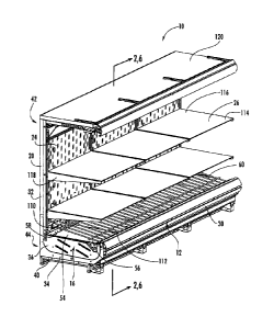
disposed at
least partially below deck 254 and a second portion 356 of each body 346 is
disposed at least
partially above deck 54. First portions 354 of bodies 346 are shown
substantially vertical,
extending below deck 254 and generally in front of or proximate to an air
outlet 268 of
cooling system 222 to receive first portion 274 of air flow 270 therein.
Second portions 356
of bodies 346 are shown substantially horizontal, extending along
substantially horizontal
deck 254 toward front wall 230 for a distance. A desired air flow distribution
and/or air flow
velocity may be achieved by adjusted by the distance that first portion 354
extends below
deck. All else equal, the farther the first portions 356 of bodies 346 of
scoops 340 extend
below the deck 254, the greater the volume of the first portion of the air
flow that is received
in scoops 340. According to other embodiments, the first portions and the
second portions
may be disposed at any of a number of angles relative to each other and/or the
deck.
[0059] Referring to FIGS. 12 and 13, the operation of air distribution system
228 is shown
according to an exemplary embodiment. Air distribution system 228 provides for
distribution
of first portion 274 of air flow 270 toward deck 254. Deck 254 is shown
disposed adjacent or
proximate to a bottom 284 of intermediate wall 224. First portion 274 of air
flow 270 is
shown directed by away from cavity 294 toward deck 254 by scoops 340. Air
distribution
system 228 further provides for distribution of second portion 276 of air flow
270 toward
deck 254 and shelves 226. Shelves 226 are shown disposed adjacent or proximate
to
intermediate wall 224 above deck 254. In this manner, air distribution system
228 provides
for enhanced air flow throughout refrigerated case 210, provides for balanced
cooling of
products displayed in refrigerated case 210, and substantially maintains the
products
displayed within refrigerated case 210 at a uniform temperature.
[0060] Referring to FIG. 12, discharge air flow portion 272 of air flow 270 is
discharged
from air outlet 268 of cooling system 222. Discharge air flow portion 272
flows generally
rearward toward rear wall 232 of frame 220. Scoops 340 receive and direct
(e.g., intercept,
divert, etc.) first portion 274 of air flow 270 away from cavity 294 and
towards deck 254.
19
CA 02675458 2009-08-13
Scoops 340 further permit second portion 276 of air flow 270 to flow
therebeneath and into
cavity 94.
[0061] Referring to FIG. 13, first portion 274 of air flow 270 is shown
encountering air
inlets 342 of scoops 340 as discharge air flow portion 272 flows substantially
rearward
according to an exemplary embodiment. Air inlets 342 receive first portion 274
of air flow
270. First portion 274 of air flow 270 flows through passages 348 defined by
bodies 346 of
scoops 340. First bends 350 of scoop bodies 346 direct first portion 274 of
air flow 270
generally vertically upward and above deck 254. Above deck 254, first portion
274 of air
flow 270 encounters second bends 352. Second bends 352 of scoop bodies 346
direct first
portion 274 of air flow 270 generally horizontally. First portion 274 of air
flow 270 then
flows substantially horizontally through passages 348 toward front wall 230 of
frame 220
until it is discharged from air outlets 344 of scoops 340. Upon being
discharged from air
outlets 344, first portion 274 of air flow 270 flows along deck 254 towards
front wall 230
until being drawn into an air return 326 and directed, as at least part of
return air flow portion
280, toward cooling system 22 where it is cooled and recirculated.
[0062] Referring further to FIG. 13, second portion 276 of air flow 270 is
shown flowing at
least partially beneath scoops 340 and intermediate wall 224 where it
encounters a surface
362 according to an exemplary embodiment. Surface 362 is configured to at
least partially
direct second portion 276 of air flow 270 into cavity 294. Second portion 276
of air flow 270
flows generally along surface 362 into cavity 294. Second portion 276 of air
flow 270 is
shown flowing through cavity 294 until being discharged from a plurality of
openings 364 in
intermediate wall 224. A canopy 320, shown disposed at least partially above
cavity 294, is
configured to help generate a pressure differential that helps discharge
second portion 276
from openings 364 in intermediate wall 224. Second portion 276 of air flow 270
flows
through openings 364 toward shelves 226, providing for cooling of products
supported on
shelves 226.
[0063] Referring back to FIG. 12, the remaining portion of second portion 276
of air flow
270 that is not distributed through openings 364 of intermediate wall 224
flows out of the top
of cavity 294 and into canopy 320. Canopy 320 helps direct the remaining air
generally
downward toward front wall 230 of frame 220, forming air curtain 278. As
discussed above,
CA 02675458 2009-08-13
air curtain 278 enhances the performance of refrigerated case 210 by providing
a boundary or
separation between the refrigerated interior or product space of refrigerated
case 10 and the
warmer ambient environment external to the case. As air curtain 278 approaches
front wall
230 of frame 220, it is drawn into air return 326 and directed, as at least
part of return air
flow portion 280, toward cooling system 222 where it is cooled and
recirculated.
[0064] Referring to FIGS. 14 and 15, a plurality of shelves 426 are provided
in refrigerated
case 410 according to a third exemplary embodiment.
[0065] Referring to FIG. 14, refrigerated case 410 further includes a cooling
system 422
configured to discharge an air flow 470, an intermediate wall 424, a plurality
of shelves 426,
an air distribution system 428, and a frame 420 (similar to cooling system 22,
air flow 70,
intermediate wall 24, shelves 26, air distribution system 28, and frame 20
previously
described). Frame 420 of refrigerated case 410 further includes a cavity 494
defined between
intermediate wall 224 and rear wall 232 (similar to cavity 94 previously
described).
[0066] Referring to FIG. 15, cooling system 422 provides an air flow 470. Air
flow 470 is
shown according to a second exemplary embodiment including a discharge air
flow portion
472. Discharge air flow portion 472 has at least one portion 476. Portion 476
of air flow has
a plurality of sub-portions, including a first sub-portion 482 and a second
sub-portion 484.
[0067] Referring further to FIGS. 14 and 15, each shelf 426 includes a front
portion 429
and a rear portion 430, wherein rear portion 430 of each shelf 426 is
generally open and
disposed adjacent or proximate to intermediate wall 424. Each shelf 426
further includes a
shelf base 564, a shelf cover 566 having a plurality of openings 568, and a
space 570 defined
therebetween. Shelf covers 566 are shown disposed at an angle relative to
shelf bases 564
and coupled thereto. Each shelf base 564 includes a front edge 572 and a rear
edge 574.
Each shelf cover 566 includes a front edge 576 and a rear edge 578. Front edge
576 of each
shelf cover 566 is coupled to front edge 572 of the corresponding shelf base
564. Rear edge
578 of each shelf cover 566 is spaced a distance from rear edge 574 of the
corresponding
shelf base 564. Spaces 570 are shown as a wedge-shaped spaces defined by the
shelf cover
and shelf base pairings. Spaces 570 generally extend from the rear edges
toward the front
edges of each shelf cover and shelf base pairing. Shelf covers 566 are
configured to be
21
CA 02675458 2009-08-13
adjustable relative to shelf bases 564, providing for the cross-section of
spaces 570 defined
therebetween to be adjusted. In the embodiment shown, the angle of shelf
covers 566 relative
to shelf bases 564 may be adjusted, changing the angle and/or the cross-
section of spaces 570
therebetween. The shelf covers may be adjusted to achieve a desired air flow
and/or air flow
velocity.
[0068] Referring to FIG. 15, openings 568 in shelf covers 566 are configured
to distribute
one or more sub-portions of portion 476 of air flow 470 received in spaces 570
through a
plurality of openings 580 in intermediate wall 424. Openings 568 are shown as
circular holes
disposed at a front portion 582 of each shelf cover 566 of shelves 426 and
arranged in a
pattern. The openings in the shelf covers are sized, shaped, and/or arranged
in a pattern
intended to achieve a desired distribution of air flow and/or maintain a
desired air flow
velocity. Openings 568 may vary in size, shape, pattern, and/or arrangement
(e.g., the shelf
cover openings may include large circular holes and/or a series of openings
forming a
honeycomb patterns, etc.). In some embodiments, openings 568 in shelf covers
566 may get
progressively larger the higher the shelf is disposed relative to intermediate
wall 424 (e.g., the
closer to the top of the intermediate wall) in order to achieve a desired air
flow and/or air
flow velocity.
[0069] According to other embodiments, openings 568 in shelf covers 566 may
form a first
pattern on one shelf and a second pattern on a shelf thereabove. The first
pattern and the
second pattern may be the same. Alternatively, the first pattern and the
second pattern may
differ. In another embodiment, the openings in the shelf cover of each shelf
may be the same
size, but may become progressively more numerous the higher the shelf is
disposed relative
to the intermediate wall. In some embodiments, the openings in the shelf
covers of a
plurality of shelves increase in both size and number the higher each shelf is
disposed relative
to the intermediate wall.
22
CA 02675458 2009-08-13
[0070] Referring further to FIG. 15, each shelf 426 is disposed relative to
intermediate wall
424 such that at least some openings 580 are located above each shelf cover
566 and some
openings 580 are located between each shelf cover 566 and shelf base 564
pairing. Openings
580 above each shelf cover 566 are intended to distribute sub-portions (e.g.,
first sub-portion
482) of portion 476 of air flow 470 above and generally along each shelf cover
566 (e.g., in a
first flow path). These sub-portions are primarily directed at rear portions
430 of shelves
426. Openings 580 between each shelf cover 566 and corresponding shelf base
564 are
intended to distribute sub-portions (e.g., second sub-portion 484) of portion
476 of air flow
470 into spaces 570 therebetween. The sub-portions of portion 476 of air flow
470 received
in spaces 570 are distributed through openings 568 (e.g., in a second flow
path). As openings
568 are disposed toward front portions 582 of shelf covers 566, the sub-
portions of portion
476 of air flow 470 received in spaces 570 are primarily directed at front
portions 429 of
shelves 426. Spaces 570 in shelf covers 566 may be configured to achieve a
desired velocity
of the sub-portions of portion 476 of air flow 470 flowing through openings
568 (e.g., the
spaces may have a cross section that generally decreases moving from the rear
portion toward
the front portion of each shelf, such as the wedge shaped space discussed
above, etc.). In
other embodiments, the shelf cover and the shelf base may be integrally formed
in any
manner wherein a space is defined therebetween, or the shelves may not include
shelf covers.
[0071] According to any preferred embodiment, a straight case is provided with
a frame, a
cooling system, an intermediate wall, a plurality of shelves, and an air
distribution system.
The frame includes a front wall and a rear wall. The cooling system includes
an air flow
device providing an air flow discharged through an air outlet. The
intermediate wall is
spaced a distance from the rear wall to define a cavity. The cavity may extend
substantially
vertically. The intermediate wall includes a plurality of openings through
which air may be
discharged. The plurality of openings may include a first set of openings
disposed
substantially below a second set of openings. Each shelf may include a front
portion and a
rear portion. The rear portions of the shelves may be disposed proximate the
second set of
openings such that the air discharged from these openings is directed toward
the shelves. A
deck extending at least partially between the intermediate wall and the front
wall of the frame
and having a front portion and a rear portion is also provided. The rear
portion of the deck is
disposed proximate the first set of openings such that air discharged from
these openings is
23
CA 02675458 2009-08-13
directed toward the deck. The air distribution system includes one or more air
diverting
devices each having first portion substantially above a second portion and a
bend defining the
transition between the first portion and the second portion. The first portion
of the air
diverting device is disposed at least partially within the cavity. The second
portion of the air
diverting device is disposed at an angle relative to the first portion of the
air diverting device
and extends generally toward the air outlet. The second portion of the air
diverting device
extends at least partially beneath the intermediate wall. The second portion
of the air
diverting device may be curved, substantially planar, or partially curved. The
air diverting
device is configured to direct a first portion of the air flow into the cavity
and through the
first set of openings and permit a second portion of the air flow to flow into
the cavity and be
directed through the second set of openings. At least one plenum may be at
least partially
defined by coupling the air diverting device and the intermediate wall, the
plenum being
configured to air directed therein by the air diverting device. An upper
barrier and/or side
flanges may be provided to help prevent the first portion of the air flow from
flowing out of
the plenum and out of the second set of openings. The plenum may further be
configured to
prevent the second portion of the air flow, directed generally rearward of the
air diverting
device, from accessing and exiting through the first set of openings.
[0072] According to another preferred embodiment, a straight case is provided
with a
frame, a cooling system, an intermediate wall, a plurality of shelves, and an
air distribution
system. The frame includes a front wall and a rear wall. The cooling system
includes an air
flow device providing an air flow discharged through an cooling system air
outlet. The
intermediate wall is spaced a distance from the rear wall to define a cavity.
The cavity may
extend substantially vertically. The intermediate wall includes a plurality of
openings
through which air may be discharged. Each shelf includes a front portion and a
rear portion.
The rear portion of each shelf may be disposed proximate the openings in the
intermediate
wall such that the air discharged from these openings is directed toward the
shelves. A deck
extending at least partially between the intermediate wall and the front wall
of the frame and
having a front portion and a rear portion is also be provided. The rear
portion of the deck is
disposed below the shelves and proximate openings in the intermediate wall.
The air
distribution system includes at least one air diverting device having a body
extending through
the deck, at least one air outlet above the deck, and at least one air inlet
below the deck. The
24
CA 02675458 2009-08-13
air inlet and the air outlet may be disposed in front of the intermediate
wall. The body of the
air diverting device at least partially forms a passage between the air inlet
and the air outlet.
The body of the air diverting device includes a first portion at least
partially above the deck
and a second portion below the deck. The body further includes a first bend
below the deck
and a second bend above the deck. The first and second bends are at least
partially curved,
defining an at least partially curved flow path therebetween. The air
diverting device is
configured to direct a first portion of the air flow away from the cavity and
toward the deck
and permit a second portion of the air flow to flow into the cavity and be
directed toward the
shelves. The second portion of the air flow is discharged from the cavity
through the
openings in the intermediate wall. The first portion is discharged through the
air outlet of the
air diverting device.
100731 According to another preferred embodiment, a straight case is provided
with a
frame, a cooling system, an intermediate wall, a plurality of shelves, and an
air distribution
system. The frame includes a front wall and a rear wall. The cooling system
includes an air
flow device providing an air flow discharged through an cooling system air
outlet. The
intermediate wall is spaced a distance from the rear wall to define a cavity.
The cavity
extends substantially vertically. The intermediate wall includes a plurality
of openings
through which air is discharged. Each shelf includes a front portion and a
rear portion. Each
shelf further includes a shelf cover disposed generally above a shelf base and
a space defined
therebetween. The shelf cover is at an angle relative to the shelf base and
the space
therebetween is a wedge-shaped space. The shelf cover is also adjustable
relative to the shelf
base to adjust the cross-section of the space therebetween. The rear portion
of each shelf is
generally open between the shelf cover and the shelf base. Each shelf cover
further includes
a plurality of openings configured to discharge sub-portions of a portion of
the air flow
therethrough. The openings in the shelf cover are disposed proximate a front
portion of the
shelf cover. The air distributions system directs air in a first flow path
above the shelf cover
toward the rear portion of the shelf. The air distribution system further
directs air in a second
flow path through the space, out the openings in the shelf cover, and toward
the front portion
of the shelf The shelves may be used in combination with one or more air
diverting devices
having any of a number of configurations.
CA 02675458 2009-08-13
[0074] As utilized herein, the terms "approximately," "about,"
"substantially," and similar
terms are intended to have a broad meaning in harmony with the common and
accepted usage
by those of ordinary skill in the art to which the subject matter of this
disclosure pertains. It
should be understood by those of skill in the art who review this disclosure
that these terms
are intended to allow a description of certain features described and claimed
without
restricting the scope of these features to the precise numerical ranges
provided. Accordingly,
these terms should be interpreted as indicating that insubstantial or
inconsequential
modifications or alterations of the subject matter described and claimed are
considered to be
within the scope of the invention as recited in the appended claims.
[0075] It should be noted that the term "exemplary" as used herein to describe
various
embodiments is intended to indicate that such embodiments are possible
examples,
representations, and/or illustrations of possible embodiments (and such term
is not intended
to connote that such embodiments are necessarily extraordinary or superlative
examples).
[0076] The terms "coupled," "connected," and the like as used herein mean the
joining of
two members directly or indirectly to one another. Such joining may be
stationary (e.g.,
permanent) or moveable (e.g., removable or releasable). Such joining may be
achieved with
the two members, or the two members and any additional intermediate members,
being
integrally formed as a single unitary body with one another, or with the two
members, or the
two members and any additional intermediate members, being attached to one
another.
[0077] It should be noted that the orientation of various elements may differ
according to
other exemplary embodiments, and that such variations are intended to be
encompassed by
the present disclosure (e.g., the scoops relative to the tower, the air flow
relative to the deck,
etc.).
[0078] It is also important to note that the construction and arrangement of
the refrigerated
case as shown in the various exemplary embodiments is illustrative only.
Although only a
few embodiments of the present inventions have been described in detail in
this disclosure,
those skilled in the art who review this disclosure will readily appreciate
that many
modifications are possible (e.g., variations in sizes, dimensions, structures,
shapes and
proportions of the various elements, values of parameters, mounting
arrangements, use of
26
CA 02675458 2009-08-13
=
,
materials, colors, orientations, etc.) without materially departing from the
novel teachings and
advantages of the subject matter disclosed herein. For example, elements shown
as integrally
formed may be constructed of multiple parts or elements, the position of
elements may be
reversed or otherwise varied, and the nature or number of discrete elements or
positions may
be altered or varied. Accordingly, all such modifications are intended to be
included within
the scope of the present invention as defined in the appended claims. The
order or sequence
of any process or method steps may be varied or re-sequenced according to
alternative
embodiments. Other substitutions, modifications, changes and omissions may be
made in the
design, operating conditions and arrangement of the various exemplary
embodiments without
departing from the scope of the present inventions.
27