Note: Descriptions are shown in the official language in which they were submitted.
CA 02675616 2009-07-15
WO 2008/090134 PCT/EP2008/050671
Novel Device
This invention relates to a dispenser device, in particular to a dispenser
device for the dispensing of products contained in sachets.
Products are frequently provided in sachets. Sachets are well known articles,
generally comprising two sheets of material joined at their edges to define an
envelope volume between them. Sachets are typically made of thin plastics or
metal,
or metal-plastics material foil laminates. To obtain access to the product
contained
within the sachet, the sachet must be opened. This is normally achieved by the
user
tearing the sachet open by hand. Although sachets are often provided with
nicks or
weakened areas at which they will preferentially tear, opening them can be a
haphazard operation with the risk of loss, damage or contamination of the
product.
US-A-4,008,657 discloses an apparatus for dispensing a continuous strip of
sachets and is provided with a moveable cutter which cuts the continuous strip
to
open the sachets to release their contents for use. The disclosed apparatus is
a
complex machine.
It is an object of the present invention to address this problem by providing
a
dispenser which can conveniently cut open a sachet with some degree of
precision as
to there the sachet is cut. It is also an object of the invention to provide
such a
dispenser in a form of a package which can easily be carried about by a person
e.g.
in a pocket or handbag etc. The latter object is particularly important for
sachets
containing medicament contents which a user may need during the day, for
example
a sachet containing a patch to be applied to the skin for the transdermal
administration of some therapeutic substance. It is also an object to provide
such a
package in a form which is cheap to manufacture i.e. requiring minimal
moulding
and/or assembly. Other objects of this invention will be apparent from the
following
description.
According to a first form of this invention a dispenser for sachets comprises
a container for containing a sachet and from which a sachet may be dispensed
for
use, the container having a slot opening in its outer surface and
communicating with
a cavity within the container, the slot opening arranged such that a sachet
may be
inserted into the slot opening to extend into the cavity, an abutment surface
within
the cavity to limit the distance the sachet may extend into the cavity, and a
cutter
-1-
CA 02675616 2009-07-15
WO 2008/090134 PCT/EP2008/050671
located within the cavity and positioned such that a sachet extending into the
cavity
may be brought into contact with the cutter to thereby cut the sachet.
The slot opening preferably comprises an aperture in the outer surface of the
container which approximates to the cross section of the sachet to be inserted
through the slot opening. Typically in its cross section perpendicular to the
insertion
direction in which the sachet is to be inserted into the slot opening such an
aperture
is relatively long relative to its width. Such a slot opening can conveniently
guide a
sachet inserted therethrough and into the cavity towards and preferably into
contact
with the cutter. The slot and/or the cavity may incorporate guide means to
further
guide an inserted sachet towards and preferably into contact with the cutter.
Such
guide means may for example comprise internal ribs within the cavity which
define
a path for the sachet within the cavity.
An abutment surface within the cavity to limit the distance the sachet may
extend into the cavity may be provided in various ways. In one way the
abutment
surface is provided by a bulkhead wall of the cavity, or internal ribs within
the
cavity, against which the sachet abuts when the sachet extends into the cavity
to a
desired extent. This abutment surface can function to determine the extent to
which
the sachet and cutter can be relatively moved in cutting contact so as to
consequently
determine the extent to which the sachet is cut. For example the dispenser may
be
arranged to cut only a starting nick in the sachet to provide a starting point
for the
user to tear the sachet fully open. Alternatively the dispenser may be
arranged to cut
the sachet fully open by severing a segment of the sachet. Additionally or
alternatively the abutment surface can function as a guide surface to guide
the sachet
into cutting contact with the cutter within the cavity as described below.
The cutter is located within the cavity and positioned such that a sachet
extending into the cavity and the cutter may be brought into contact with each
other
to thereby cut the sachet. In this first embodiment the cutter may be
configured and
positioned within and relative to the cavity and the abutment in various
constructions
to cut the sachet in various alternative constructions.
In a first construction the cutter is positioned and aligned within the cavity
such that the sachet may be brought into contact with the cutter by a movement
of
-2-
CA 02675616 2009-07-15
WO 2008/090134 PCT/EP2008/050671
the sachet within the cavity in a first direction, and then brought out of
contact with
the cutter by a reciprocal movement of the sachet in an opposite second
direction.
In this first construction the cutter may be arranged to cut the sachet either
on the movement of the sachet in the first direction or in the second
direction.
As sachets are typically flexible and liable to crumple under compression
such an arrangement can advantageously be used to cause the sachet to be cut
whilst
the sachet is under tension. This may be achieved by a cutter configured to
cut the
sachet whilst the sachet is moved, e.g. pulled, in the second direction out of
contact
with the cutter.
For example the first direction may be the insertion direction in which the
sachet is inserted into the slot opening and the second direction may be the
withdrawal direction in which the sachet is withdrawn from the slot opening.
In such
a construction the abutment surface functions to limit the distance the sachet
can be
inserted into the cavity in the insertion direction, and consequently the
distance the
sachet needs to be withdrawn from the cavity and slot opening, and hence the
extent
to which the sachet is cut.
Alternatively for example both the first and second directions may be
directions perpendicular to the insertion direction, such that the sachet is
inserted
into the slot opening in an insertion direction, then brought into contact
with the
cutter by a movement of the sachet within the cavity in a first direction
perpendicular to this insertion direction, and then brought out of contact
with the
cutter by a reciprocal movement of the sachet in an opposite second direction
perpendicular to the insertion direction, and then withdrawn from the slot
opening in
a withdrawal direction. In such a construction the abutment surface can be
aligned to
guide the sachet in sliding contact with the abutment surface as the sachet is
moved
in the first and second directions perpendicular to the insertion direction.
This cutting action on movement of the sachet in the second direction may be
achieved in various ways. For example the cutter may have a cutting edge which
faces in the first, e.g. insertion, direction and a non-cutting surface facing
in the
second, e.g. withdrawal, direction. For example the container may have a slot
opening into which the sachet may be inserted in an insertion direction and
-3-
CA 02675616 2009-07-15
WO 2008/090134 PCT/EP2008/050671
withdrawn in an opposite reciprocal withdrawal direction, and the cutter has a
cutting edge facing in the insertion direction away from the slot opening.
This first construction of the dispenser of the invention is suitable to cut a
starting nick in the sachet.
In a second construction the cavity defines a linear guide groove having the
slot opening at an insertion end of the groove and having an exit opening at
an exit
end of the groove, such that the sachet may be inserted into the groove via
the slot
opening, moved along the groove from the slot opening toward the exit opening,
and then to exit from the cavity via the exit opening, and the cutter is
located within
the cavity between the slot opening and exit opening with its cutting edge
aligned
with the guide groove such that the cutter intercepts the sachet as the sachet
moves
along the groove and the cutter cuts the sachet.
In this second construction the sachet is in effect "swiped" along this guide
groove.
In this second construction the abutment surface can limit the distance to
which the sachet can be inserted into the cavity, i.e. the guide groove, and
is
suitably aligned so that the sachet may be passed through the guide groove in
sliding
contact with the abutment surface so that the abutment surface functions to
guide the
sachet. The cutter is positioned at a distance from the abutment surface so
that the
cutter cuts the sachet at a corresponding distance from the edge of the sachet
which
moves in sliding contact with the abutment surface.
This second construction of the dispenser of the invention is suitable to cut
a
starting nick in the sachet or to cut the sachet completely open by severing a
segment of the sachet.
In a third construction the cutter is moveably mounted relative to the cavity
so that the cutter may be moved relative to a sachet to thereby cut open the
sachet.
In this construction suitably the slot opening, cavity and moveably mounted
cutter are relatively disposed such that a sachet may be inserted into the
cavity in an
insertion direction via the slot opening to abut against the abutment surface,
and the
cutter is moveable in a direction perpendicular to the insertion direction.
-4-
CA 02675616 2009-07-15
WO 2008/090134 PCT/EP2008/050671
The extent of moveability of the cutter may be such that the cutter only cuts
a starting nick in the sachet, or alternatively that the cutter completely
severs a
segment of the sachet to thereby open the sachet.
Ways of moveably mounting the cutter will be apparent to those skilled in
the art. In one way the cutter may be slideably moveably mounted in a guide
slot,
suitably having an operating handle external to the container by which the
cutter
may be operated.
In this third construction the abutment surface can function to limit the
distance the sachet can be inserted into the cavity in the insertion
direction, and the
distance in the insertion direction between the cutter and the abutment
surface can
determine the corresponding distance from the edge of the sachet at which the
sachet
is cut.
In a second embodiment of the invention a dispenser for sachets is provided
comprising a container for containing a sachet and from which a sachet may be
dispensed'for use, the container body incorporating a cutter with which a
sachet
dispensed from the container may be brought into contact to thereby cut open
the
sachet, the dispenser being constructed to dispense a sachet along a
dispensing path,
and the cutter may be mounted to intercept a sachet traveling along this
dispensing
path to thereby cut open the sachet.
Such a dispensing path may be defined by a dispensing conduit along which
the sachet is dispensed towards a dispensing outlet opening.
In this third embodiment the sachet may have a straight edge, e.g. it may be
rectangular, and the direction of the dispensing path may be parallel to the
straight
edge direction of the sachet.
In use, a sachet may be dispensed from the container of this third
embodiment along the dispensing path, and in the course of following the
dispensing
path the sachet is brought into contact with the cutter to thereby cut the
sachet.
The cutter may comprise a sharp blade, e.g. made of metal or ceramic.
Preferably the cutter is shielded to prevent accidental contact with the user
and consequent injury. This may be achieved for example by mounting the cutter
deep within the cavity so that a user's fingers cannot be easily inserted
through the
slot opening to contact the cutter. This shielding is also achieved in forms
of the
-5-
CA 02675616 2009-07-15
WO 2008/090134 PCT/EP2008/050671
dispenser of the invention in which the cutting edge of the cutter faces away
from
the insertion direction.
Suitable relative positions of the slot opening, cavity and cutter can easily
be
determined empirically by those skilled in the art to cut any specific sachet
at a
suitable position and to a suitable extent.
The dispenser of the invention is preferably in the form of a package which
can be easily be carried about by a person e.g. in a pocket or handbag etc.
Such a
package may be made of commonly used packaging materials, for example plastics
materials, metal or stiff cardboard. Suitable shape and dimensions for such a
package will be apparent to those skilled in the packaging art. An overall
preferred
configuration of the dispenser of the first embodiment suitably comprises an
elongate tetragonal, i.e. flattened box shape, preferably with rounded corners
and
edges, having a dispensing opening for the sachets at one end surface and the
slot
opening, aperture etc. at the opposite longitudinal surface.
Consequently an overall preferred form of the dispenser of this invention is
one according to the first embodiment and comprises a tetragonal container
having a
dispensing opening for the sachets at one surface of the container and the
slot
opening at the opposite surface, the slot opening comprising an aperture in
the outer
surface of the container being relatively long relative to its width, the
cavity
incorporating guide means to guide an inserted sachet towards and into contact
with
the cutter, the abutment surface positioned to limit the extent to which a
sachet can
be inserted in the insertion direction into the cavity, the cutter configured
such that
the sachet is brought into contact with the cutter by a movement of the sachet
within
the cavity in the insertion direction, and then brought out of contact with
the cutter
by a reciprocal movement of the sachet in the withdrawal direction, the cutter
having a cutting edge facing in the insertion direction to cut the sachet on
the
movement of the sachet in the withdrawal direction.
By means of the dispenser of the invention sachets may be easily cut open
without the risks encountered in tearing them open by hand. Sachets are
typically
generally rectangular (the term includes square) and in the dispenser of the
invention
the cutter may be so incorporated into the dispenser such that the sachet can
be cut
parallel to a straight edge of such a rectangular sachet.
-6-
CA 02675616 2009-07-15
WO 2008/090134 PCT/EP2008/050671
The invention will now be described by way of example only with reference
to the accompanying drawings.
Figs. 1 - 3 show a dispenser of the first embodiment.
Figs. 4 - 6 show the operation of the dispenser of Fig. 1.
Figs. 7 - 11 show an alternative form of dispenser of the first embodiment.
Figs. 12- 15 show an alternative form of dispenser of the first embodiment
Figs. 16- 20 show an alternative form of dispenser of the first embodiment
Figs. 21- 23 show an alternative form of dispenser of the first embodiment
Figs. 24- 26 show a dispenser of the second embodiment
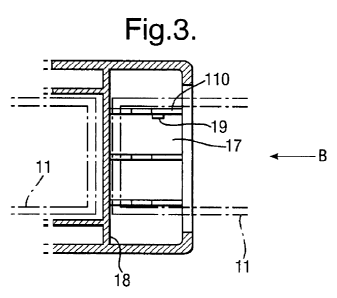
Referring to Figs 1 - 6 a dispenser 10 overall for sachets 11 is shown in a
longitudinal section view in Fig. 1, in a part plan sectional view as cut
along the line
A---A and seen looking downwards in Fig. 2, and in an end looking in the
longitudinal direction along the direction B in Fig. 3. Dispenser 10 comprises
a
container 12 being of a generally tetragonal box shape with rounded edges and
corners, capable of containing plural sachets 11 and from which sachets may be
dispensed for use from a dispensing opening 13 closed with a hinged closure
14.
The container incorporates internal ribs 15 to define a containing space more
closely
accommodated to the shape of sachets 11 contained therein. The container 12 is
conventionally moulded in plastics material such as polypropylene and is
conveniently made in two mating upper and lower parts 121, 121 meeting at a
seam
line 123.
The container 12 is of an overall tetragonal shape and has a slot opening 16
in its outer end surface, which as seen in Fig. 2 comprises an aperture in the
outer
surface of the container 12 at the longitudinally opposite end to the
dispensing
opening 13, and the slot opening 16 approximates to the cross section of the
sachet
11 to be inserted in the insertion direction being the longitudinal direction
of the
dispenser 10 through the slot opening 16, being relatively long relative to
its width.
The slot opening 16 communicates with a cavity 17 within the container 12.
As more clearly seen in Figs 4, 5 and 6 which show simplified plan views with
the
outline of cavity 17 shown in dotted outline the slot opening 16 is arranged
such that
a sachet 11 may be inserted in an insertion direction as shown by the arrow in
Fig. 5
into the slot opening 16 to extend into the cavity 17. An abutment surface
within the
-7-
CA 02675616 2009-07-15
WO 2008/090134 PCT/EP2008/050671
cavity 17 is provided by a bulkhead wall 18 which limits the distance the
sachet 11
may extend in the insertion direction into the cavity 17 by abutment of the
leading
edge of the sachet 11 against the bulkhead wall 18. A cutter 19 is located
within the
cavity 17. The cutter 19 is attached to a rib 110 which serves both as a
mounting for
the cutter 19 and together with other ribs 111 define a path 112 for the
sachet 11
within the cavity. This path 112 is angled, with the cutter 19 located in a
concave
part of the path 112.
The cutter 19 is positioned and aligned within the cavity 17 such that the
sachet 11 is brought into contact with the cutter 19 in the insertion
direction, and is
then brought out of contact with the cutter 19 by a reciprocal movement of the
sachet in the opposite withdrawal direction being the direction of the arrow
in Fig.
6.
The cutter 19 has a cutting edge 191 which faces in the insertion direction
away from the slot opening 16 and a non-cutting surface 192 facing in the
withdrawal direction. The cutter 19 has a sawtooth profile and the non-cutting
surface 192 is inclined at a non-perpendicular angle to the insertion
direction so that
the sachet 11 can ride over the non-cutting surface 192 without being cut, but
being
scored.
In operation as seen in Figs 4, 5 and 6 the sachet 11 is first inserted as
seen
in Figs. 3 and 5 into the slot opening 16 in the insertion direction until the
sachet 11
abuts against the wall 18. As the sachet is inserted it follows the path 112
and rides
over the non-cutting surface 192 of the cutter 19 so as to be scored. The
sachet is
then withdrawn in the withdrawal direction as seen in Fig. 6. Because the path
112
is an angled path with the cutter 19 located in the convexity of the angle,
the tension
in the sachet 11 as it is pulled in the withdrawal direction urges the sachet
11 into
cutting contact with the cutting edge 191 of cutter 19. As a result a nick 113
is cut
in the sachet 11 which a user may use to tear open the sachet 11.
Referring to Figs. 7 - 11, an alternative form of the dispenser of the first
embodiment is shown in perspective views in Figs. 7 and 8, and in partially
opened
perspective views in Figs. 9, 10 and 11.
The dispenser 20 overall comprises a container 21 of generally known
tetragonal box type with an openable closure 22 which may be opened to enable
a
-8-
CA 02675616 2009-07-15
WO 2008/090134 PCT/EP2008/050671
user to access a rectangular sachet 23 therefrom. The container 21 has a slot
opening 24 in its outer surface, comprising an elongate aperture extending
partly
across the width of the container 21 and communicating with a cavity 25 within
the
container.
The cavity 25 has an end-stop abutment 26 comprising an end wall of the
cavity 25. As is seen in Figs. 8 and 9 a sachet 23 inserted into the slot
opening 24
and extending into cavity 25 abuts against this abutment 26 when inserted in
the
insertion direction being the arrow in Fig. 8. This abutment limits the extent
to
which the sachet 23 can be inserted into the cavity 25.
A cutter 27 is located in the cavity 25. The cutter 27 comprises a metal
cutting edge 28 on the side of cutter 27 facing away from the slot opening 24,
and
has a blunt plastics material non-cutting edge 29 facing the slot opening 24.
The
cutter 27 is mounted resiliently relative to the wa11210 defining the
container 21 by
means of the resilient plastics material flap 211.
As seen in Fig. 10, as the sachet 23 is inserted into the slot opening 24 the
sachet 23 is brought into contact with the non-cutting edge 29 of cutter 27.
This
causes the cutter 27 to be displaced resiliently, and the cutter 27 merely
scores the
sachet 23. As is seen in Fig. 11, when the sachet is withdrawn from the slot
opening
24 in the withdrawal direction the cutting edge 28 of cutter 27 contacts the
sachet to
cut a notch 212 in the sachet 23. The cavity 25 is provided with internal ribs
213 to
guide the sachet 23 as it is inserted into cavity 25. It is seen that the
sachet 23 is cut
whilst the sachet 23 is under tension, being pulled in the withdrawal
direction out of
the slot 25.
Referring to Figs 12, 13, 14 and 15 another alternative form of the dispenser
30 overall, being again of generally tetragonal shape with rounded edges and
corners, is shown. Figs. 12, 13 and 14 are plan views showing some internal
features in dotted outline. Fig. 15 is an end view looking in the insertion
direction
shown by the arrow in Fig. 12. In a manner analogous to Figs. 1 - 11 a sachet
31
is inserted into the slot opening 32 communicating with the internal cavity 33
within
which is located a cutter 34 of analogous construction to that 19 shown in
Figs. 1 -
6.
-9-
CA 02675616 2009-07-15
WO 2008/090134 PCT/EP2008/050671
However in the dispenser of Figs. 12 - 15 the cutting edge 341 of cutter 34
is oriented in a direction perpendicular to the insertion direction.
In use, a sachet 31 is inserted through the slot opening 32 in the insertion
direction being the arrow shown in Fig. 12. The sachet then abuts against the
abutment surface 35 being a bulkhead wall of the cavity 33 analogous to that
18 of
Figs. 1 - 6. This abutment limits the distance the sachet 31 can be inserted
in this
direction.
As seen in Fig. 13 the sachet 31 is then moved in a first direction shown by
the arrow in Fig. 13 perpendicular to the insertion direction in which it is
brought
into contact with the non-cutting surface 342 of cutter 34 in a manner
analogous to
Figs. 1 - 6. The abutment surface 35 is aligned to guide the sachet 31 in
sliding
contact with the abutment surface 35 as the sachet 31 is moved in this first
direction,
until the sachet abuts against a further abutment surface 36 being an end of
the
cavity 33. The sachet 31 is then brought out of contact with the cutter 34 by
a
reciprocal movement of the sachet in an opposite second direction
perpendicular to
the insertion direction shown by the arrow in Fig. 14, and engages with the
cutting
edge 341 of the cutter 34, which faces in the first direction, to be cut in a
manner
analogous to Fig. 6. The sachet 31 may then be withdrawn from the cavity 33 in
a
withdrawal direction which may be a direction opposite to the arrow in Fig.
12, or a
continued movement in the direction of the arrow of Fig. 14. It is seen in
Fig. 14
that a starting nick 37 has been cut in the sachet to provide a starting point
for the
user to tear the sachet 33 fully open.
Referring to Figs. 16-20, a dispenser 40 overall of the first embodiment
comprises a container 41 of generally known box type with an openable closure
42
which may be opened to enable a user to access a sachet 43 therefrom. Figs.
16, 17
and 18 show plan views, with concealed internal features shown by dashed
lines.
Fig. 19 is an end view looking at the dispenser upwardly as drawn. Fig. 20 is
a
cross-sectional view of the lower end (as seen) of the container as cut along
the line
A- A of Fig. 16.
In the dispenser 40 a cavity is in the form of a linear guide groove 44 having
a slot opening 45 at an insertion end of the groove 44 and having an exit
opening 46
at an exit end of the groove 44. As seen in Fig. 17 a sachet 43 may be
inserted into
-10-
CA 02675616 2009-07-15
WO 2008/090134 PCT/EP2008/050671
the groove 44 via the slot opening 45 in the direction shown by the arrow in
Fig. 17
and moved in this direction along the groove 44 from the slot opening 45
toward the
exit opening 46, and to exit from the groove 44 via the exit opening 46. A
cutter 47
is located within the groove 44 between the slot opening 45 and exit opening
46 with
its cutting edge 471 aligned with the guide groove 44 such that the cutter 47
intercepts the sachet 43 as the sachet 43 moves along the groove 44 and the
cutter
47 cuts the sachet 43.
In the dispenser 40 an abutment surface 48 is provided being a side surface
of the groove 44, and is aligned so that the sachet 43 may be passed through
the
guide groove 44 in sliding contact with the abutment surface 48 so that the
abutment
surface 48 functions to guide the sachet 43. The abutment surface 48 also
limits the
distance the sachet 43 can be inserted into the groove 44. The cutter 47 is
positioned
at a distance from the abutment surface 48 so that the cutter 47 cuts the
sachet 43 at
a corresponding distance from the edge of the sachet 43 which moves in sliding
contact with the abutment surface 48.
As seen in Fig. 18 the dispenser of the invention is suitable to cut the
sachet
completely open by severing a segment 431 of the sachet. By a less complete
movement of the sachet along the groove 44 the cutter 47 may be used to cut
only a
starting nick in the sachet 43.
Referring to Figs. 21, 22 and 23 a dispenser 50 overall is shown. This
comprises a container 51 of generally known box type with an openable closure
52
which may be opened to enable a user to access a sachet 53 therefrom. Figs. 21
and
22 show orthogonal views, with concealed internal features shown by dashed
lines.
Fig. 23 is a cross-sectional view of the lower end (as seen) of the container
51 as cut
along the line B- B of Fig. 5.
In this dispenser the container 51 has a slot opening 54 in its outer surface
communicating with cavity 55 into which a sachet 53 may be inserted as seen in
Fig. 22. The cavity 55 has an end stop abutment 56 being a side surface of the
cavity 55, such that the sachet 53 may be inserted into the cavity 55 such
that its
edge abuts against the surface 56 to limit the distance the sachet 53 can be
inserted
into the cavity 55. The sachet 53 has a straight edge, being rectangular.
-11-
CA 02675616 2009-07-15
WO 2008/090134 PCT/EP2008/050671
A cutter 57 is moveably mounted relative to the cavity 55 by a snap fitting of
the edge of the cutter 57 into a guide slot 58 in a side wall of the cavity
55. The
cutter 57 incorporates a sharp metal cutting blade 59 extending across most of
the
cavity 55. The blade 58 may be moved within the cavity 55 relative to the
sachet 53
therein, in the direction of the arrow shown in Fig. 22 to thereby cut open
the sachet
53 and to sever a segment of the sachet 53 analogous to Fig. 18.
Referring to Figs. 24, 25 and 26, a dispenser of the second embodiment
shown overall 60 comprises a container 61 of generally known box type, which
contains sachets 62 which can be dispensed therefrom along a dispensing path
63,
being a channel more clearly seen in Fig. 26, by means of a known type of
roller
dispensing mechanism operated from outside the container 61 by roller 64.
Figs. 24
and 25 show orthogonal views, with concealed internal features shown by dashed
lines. Fig. 26 is a cross-sectional view across the dispensing path, of the
container
as cut along the line C - C of Fig. 25.
A cutter 65 being a sharp metal blade is mounted across dispensing path 63
to intercept a sachet 62 traveling along this dispensing path 33 to thereby
cut open
the sachet by severing the segment 661.
In this second embodiment the sachet 62 has a straight edge, being
rectangular, and the direction of the dispensing path 63 is parallel to the
long
straight edge direction of the sachet 62.
A typical size for the generally tetragonal dispensers 10, 20, 30, 40, 50, 60
is ca. 10cm (longitudinal direction) x 6cm (width direction) x 1.7 cm (depth
direction). These dimensions are generally suitable for sachets to contain a
medicinal patch e.g. a transdermal patch, and convenient for carrying in a
pocket or
handbag etc. A suitable manufacturing material is polypropylene. It is clearly
seen
from Figs. 1 - 26 how the sharp blade of the cutter is shielded by being
mounted
within the cavity or in the dispensing path to prevent accidental contact with
the user
and consequent injury.
-12-