Note: Descriptions are shown in the official language in which they were submitted.
CA 02676171 2009-07-22
WO 2008/103098
PCT/SE2008/000111
ROTATION VALVE FOR SAMPLE INJECTION
Field of the invention
The present invention relates to valves and more specifically to rotary valves
used to introduce a
sample into the flow path of an analytical or preparative instrument, such as
a liquid
chromatography system (LCS).
Background
Valves are commonly used in devices that involve the transportation of a
fluid. A typical type of valve
for example used in laboratory systems of moderate sizes, is the rotary valve.
Generally, a rotary valve has a stationary body, herein called a stator, which
co-operates with a
rotating body, herein called a rotor.
The stator is provided with a number of inlet and outlet ports. The ports are
via bores in fluid
communication with a corresponding set of orifices on an inner stator face.
The inner stator face is
an inner surface of the stator that is in fluid tight contact with an inner
rotor face of the rotor. The
rotor is typically formed as a disc and the inner rotor face is pressed
against the inner stator face in
rotating co-operation. The inner rotor face is provided with one or more
grooves which interconnect
different orifices depending on the rotary position of the rotator with
respect to the stator.
Rotary valves can be designed to withstand high pressures (such as pressures
above 30 MPa). They
can be made from a range of materials, such as stainless steel, high
performance polymeric
materials and ceramics.
The number of inlets/outlets as well as the design of grooves in the rotor or
the stator reflects the
intended use of a specific valve.
A common type of multi-purpose valve has one inlet port (typically placed in
the rotary axis of the
valve) and a number of outlets ports that are placed equidistantly around the
inlet port. The rotor
has a single, radially extending groove that has one end in the rotary centre,
thereby always
connecting to the inlet, while the other end connects to any one of the
outlets depending on the
angular position of the rotor with respect to the stator. Such a valve is
useful to direct a flow from
the inlet to any of the outlets - one at a time.
CA 02676171 2009-07-22
WO 2008/103098
PCT/SE2008/000111
2
More complicated arrangements, tailor-made to perform one or several specific
tasks, are possible.
For instance, rotary valves may be used to introduce a fluid sample into the
fluid path of an
analytical system.
A typical example of such a valve is the INV-907 valve available from GE
Healthcare. A schematic
illustration of this valve is provided in Fig. 1 to 3. The valve 20 has a
first inlet 1 for connection to a
liquid source (such as a pump), a second inlet 2 for introduction of a sample
(typically using a syringe
or a dedicated sample pump), a third inlet 3 and a first outlet 4 to/from a
device for temporary
storage of the fluid sample such as a retaining capillary loop 22 (well known
within the art), and a
second outlet 5 that connects the valve to the downstream part of the
analytical or preparative
system e.g. an AKTAexplorer system available from GE Healthcare. In addition,
the valve has two
waste outlets 6, 7 to allow a fluid to exit the valve directly to waste.
The orifices of the inner stator face of the INV-907 are represented by
circles in Fig. 1-3, such as the
circle 23 in the Fig. 2. In addition, a groove 24 is provided in the inner
stator face.
In the figures, the rotor is represented by its grooves 25, 26, 27. When the
rotor is rotated, the
grooves change positions with respect to the inner stator face, thus enabling
new flow paths
through the valve.
Fig. 1 shows a "load position", wherein a sample may be introduced via the
rotor groove 25 into the
capillary loop 22 for temporary storage. At the same time the pump can provide
a flow through the
remaining system via the rotor groove 27. In this position, the stator groove
24 forms a small cul-de-
sac.
Fig. 2 shows an "inject position", wherein the valve is now rotated 45 to
allow the capillary loop 22
to form a part of the overall flow path of the system. The pump forces, via
stator groove 24 and rotor
grooves 27 and 25, the sample out of the capillary loop into the system for
any separation, detection
or other feature provided by the system. In this position, a part of the
groove 27 forms a small cul-
de-sac.
Fig. 3 shows a "waste position", allowing the pump to direct fluid directly to
a waste outlet via rotor
groove 27.
As mentioned above, the sample may be introduced either with a syringe or a
dedicated sample
pump. Using a conventional injection valve, for example of the type shown,
requires that the sample
CA 02676171 2014-08-25
31154-7
3
pump is connected to the port that alternatively should be used for the
syringe, i.e.
both alternatives could not be used at the same time.
Therefore the user has to re-plumb the system to alternate between these
operative
modes which reduce the flexibility of the system.
Summary of the invention
In some aspect of the invention, a sample injection valve that is more
flexible for the
user is provided.
According to one aspect of the invention, there is provided a rotary valve
adapted for
injection of a fluid sample into a flow path, the valve comprising a stator
and a rotor,
said stator comprising a number of connection ports protruding into the stator
and
each ending in an orifice on an inner stator face, which is a face of the
stator making
contact in a fluid tight manner with an inner rotor face of the rotor, said
inner rotor
face being rotatably movable around a rotational axis (RA) relative to the
inner stator
face, wherein said inner stator face comprises: a first inlet orifice
communicating with
a first inlet port to the stator, said first inlet orifice being positioned
essentially
centrally in the inner stator face, which center coincides essentially with
the rotary
axis (RA) of the valve, a second inlet orifice communicating with a second
inlet port to
the stator, a third inlet orifice communicating with a third inlet port to the
stator, a first
outlet orifice communicating with a first outlet port of the stator, a second
outlet orifice
communicating with a second outlet port of the stator, a third outlet orifice
communicating with a third outlet port of the stator, a first connection
orifice
communicating with a first connection port of the stator, a second connection
orifice
communicating with a second connection port of the stator, and wherein said
second
and third inlet orifices, said first, second and third outlet orifices and
said first and
second connection orifices are distributed substantially on a circle around
the center
of the inner stator face, said circle having a radius (R), and further wherein
said inner
rotor face comprises a first groove, a second groove, a third groove, a fourth
groove
CA 02676171 2014-08-25
31154-7
3a
and a fifth groove so arranged that, in a first rotary position of the rotor:
the first
groove connects the first connection orifice with the second outlet orifice,
the second
groove connects the first inlet orifice with the first outlet orifice, and the
third groove
connects the second connection orifice with the third inlet orifice in a
second rotary
position of the rotor: the second groove connects the first inlet orifice with
the first
connection orifice, the fourth groove connects the first outlet orifice with
the second
connection orifice, and the fifth groove connects the second inlet orifice
with the third
outlet orifice, in a third rotary position of the rotor: the fourth groove
connects the
second outlet orifice with the first connection orifice, and the fifth groove
connects the
second inlet orifice with the second connection orifice.
Hereby a sample injection valve is achieved which allows sample to be applied
both
by hand (for instance using a syringe) or automatically (such as by using a
dedicated
sample pump).
Brief description of the drawings
Figure 1 is a schematic view of a prior art introduction valve in a load
position.
Figure 2 shows the valve of Figure 1 in an inject position.
Figure 3 shows the valve of Figure 1 in a waste position.
Figure 4 is a schematic side view of a rotary valve.
Figure 5 shows the front side of a valve stator according to one embodiment of
the
invention.
Figure 6 shows the inner stator face of the stator of Figure 5.
Figure 7 shows the angular distribution of the orifices in the inner stator
face
according to one embodiment of the invention.
CA 02676171 2014-08-25
. 31154-7
3b
Figure 8 shows the inner rotor face of a rotor according to one embodiment of
the
invention.
Figure 9 shows the positions of the grooves in the inner rotor face according
to one
embodiment of the invention.
Figure 10 is a schematic view of a first rotor position.
Figure 11 is a schematic view of a second rotor position.
Figure 12 is a schematic view of a third rotor position.
Figure 13 is a schematic view of a fourth rotor position.
Detailed description of the invention
The main parts of a typical rotary valve 10 are schematically shown in Fig. 4
(wherein
no brackets or similar load carrying or fastening elements are shown). The
rotary
valve 10 has a stator 11, a rotor
CA 02676171 2009-07-22
WO 2008/103098
PCT/SE2008/000111
4
12, a rotary shaft 13 that optionally may be provided with means (not shown)
for recognizing its
angular position and a driving unit 14 typically comprising a gear box and a
motor (although a valve
also may be operated manually). The rotor is rotatable with respect to the
stator around a rotary
axis RA of the valve.
The stator 11, which is fixed with respect to the instrument into which it is
built, is provided with
ports (not shown in Fig. 4) for fluid communication with a fluid source and
any components with
which the valve is to co-operate. The ports may be positioned on any suitable
position on the
exterior surface of the stator. The ports are provided with means to connect
capillaries or tubing.
Such means may be of any suitable type, such as conventional Valco fittings
well known to anyone
skilled in the art. The ports are via channels in fluid communication with a
corresponding set of
orifices on an inner stator face 11a, i.e. that surface of the stator 11 that
during operation is in
contact with the rotor 12.
The rotor 12 is typically formed as a disc and has an inner rotor face 12a
that is that face that is
pressed against the inner stator face 11a during operation. The inner rotor
face 12a is provided with
one or more grooves which interconnect different orifices of the inner stator
face 110 depending on
the rotary position of the rotor 12 with respect to the stator 11.
Fig. 5 shows a simplified perspective view of the front side of a stator 11
according to one
embodiment of the invention. The front side is here the side of the stator 11
opposite the inner stator
face 11a. Inlet and outlet ports 31a-38a are illustrated.
Generally, it should be noticed that the angular position of ports, grooves
and similar shown in the
figures of the present application could differ between different embodiments
of the invention, i.e.
they could be turned with respect to the rotary axis of the valve, mirrored or
altered in other ways as
long as their mutual co-operation is still according to the inventive idea.
In addition, since the inlet/outlet ports in the stator are connected to
orifices on the inner stator face
11a via bores (or any type of channels) it is possible to arrange the ports in
a way that differs from
the pattern of orifices on the inner stator face 11a by making non-linear
channels between the ports
and the orifices. The ports into the stator can even be positioned on another
outer surface of the
stator than the front side. However, for reasons of simplicity, the ports are
shown as being
positioned in-line with the inner stator face orifices as will be described
below in relation to Figure 6.
CA 02676171 2009-07-22
WO 2008/103098
PCT/SE2008/000111
Thus, the stator 11 according to one embodiment of the present invention has
eight ports 31a-38a
that are used to connect the valve to all desired operative components of the
instrument. According
to other embodiments of the invention one or more additional orifices and
ports can be provided to
give some additional features to the valve.
5
Port 31a is called a first inlet port 31a. It is positioned essentially in the
middle of the stator and is
used as inlet port from a main liquid source of the instrument, such as a
pump, herein called the
system pump. In the case of a Liquid Chromatography System, LCS, the system
pump provides a
flow of a single, so called buffer liquid or, alternatively, a fixed or
variable mixture of two or more
buffer liquids. Port 34a is called a first outlet port 34a and serves as the
outlet port from which the
liquid is allowed to exit to the remaining part of the instrument.
A retaining loop, such as a conventional capillary loop for use in a LCS, is
in this embodiment
connected at one end to a first connection port 32a and at the other end to a
second connection
port 35a.
Two ports 36a, 37a, here called second and third inlet ports 36a, 37h are
provided for introduction of
a sample. In the preferred embodiment shown, the third inlet port 37a is
intended for manual
sample injection, typically using a syringe, while the second inlet port 36a
is intended to be
connected to a dedicated sample pump. The sample pump may be integrated in the
instrument, or it
may be a stand-alone device.
The ports 33a and 38a are called second and third outlet ports 33a and 38a and
are in this
embodiment waste outlet ports.
Fig. 6 is a perspective view of the stator 11 of Fig. 5 viewed from the other
side, i.e. the inner stator
face side 11a. Note that each port is connected to the inner stator face 11a
via a channel ending in
an orifice 32b-38b shown in the figure. For reason of simplicity, the orifice
with number 32b is
connected to the port with number 32a and so on.
In addition to the orifices connected to the ports, a stator groove 39 is in
this illustrated embodiment
provided in the inner stator face 11a. The stator groove 39 is typically of
the same width as an orifice
diameter. It should be noted that although the stator groove 39 is preferred
in order to allow the
system pump to pump liquid through the system while the sample pump fills the
loop (this will be
described in detail below), it is not essential for the inventive idea.
Without the stator groove 39 the
system pump must either be at still when the sample pump fills the loop or
there should be an
CA 02676171 2009-07-22
WO 2008/103098
PCT/SE2008/000111
6
additional waste outlet provided in the stator. For example another waste
outlet may be provided
between the second connection orifice 35b and the second inlet orifice 36b.
Looking at the inner stator face 11a, the general angular distribution of the
orifices and the ends of
the groove 39 for one embodiment of the invention is illustrated in Fig. 7.
The positions for orifices,
groove ends (and not used positions) are here shown to be equally distributed
around the center of
the stator (which center coincides with the rotary axis of the valve). As
described above the positions
of the orifices can be varied slightly without departing from the inventive
idea. Since there are 12
such positions on the stator according to this embodiment, the partition angle
a is 30 in this
embodiment. All these positions are placed with essentially the same radial
distance R to the
rotational axis of the valve.
The inner rotor face 12a of the rotor 12 of a valve embodiment according to
the present invention is
shown in Fig. 8. It is provided with five grooves, called the first, second,
third, fourth and fifth groove
41-45. The mutual positions and shapes of the grooves are more clearly
illustrated in Fig. 9.
Each groove has both its ends ending at essentially the same radial distance R
from the center,
except for one end of groove 42 that ends in the center of the inner rotor
face 12a (coinciding with
the rotary axis of the valve). Of course, the radial distance R for the rotor
is the same as the
corresponding radial distance R of the stator. The first groove 41 extends
over an angle a, which in
the present embodiment is 30 . The second groove 42 is a straight groove from
the center of the
inner rotor face 12a out towards the rim, with a length of R, and is parted
from the nearest end of
the first groove 41 by the angle a. The third groove 43 begins at a position
parted by the angle a
from second groove 42, and ends at a position that is separated from the start
position by an angle
of 3 a. It is bent inwards toward the centre to form a knee 48 (or
alternatively in an arcuate shape).
The fourth groove 44, which occupies angle a, is equidistantly placed between
the ends of groove 43.
The fifth groove 45 has a shape similar to that of the third groove 43 (with a
knee 47 displaced
inwardly towards the center) but the end points are parted by an angle of 2 a,
and begins at an
angle a from the closest end of the third groove 43.
When assembled, the inner rotor face 12a is pressed against the inner stator
face 11a in a manner
that is typical for any conventional rotary valve (which is well known for
anyone skilled in the art, and
will not be explained herein). Depending on the mutual angular positions of
the rotor 12 and the
stator 11 different operation modes are obtained for the valve. These are
illustrated in Fig. 10-13,
wherein the grooves of the rotor are indicated by thick lines.
CA 02676171 2009-07-22
WO 2008/103098
PCT/SE2008/000111
7
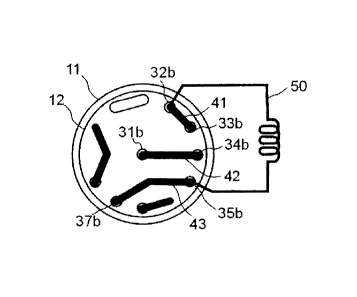
In the first rotor position, as shown in Fig. 10, the valve allows two
separate flow paths.
Fluid entering the first inlet orifice 31b, typically from a pump, such as a
system pump of a LCS, and
of course through the first inlet port 31a, is allowed to pass through the
valve via the second groove
42 and out of the first outlet orifice 34b and further out through the first
outlet port 34a. In the case
of a LCS, the first outlet port 34a is intended to be connected to the main
operative components of
the instrument such as a chromatography column and monitoring devices such as
UV monitors. In
Figures 10-13 grooves and orifices are shown and referred to and it is
understood that each of said
orifice mentioned is connected to a corresponding port as described above.
At the same time it is possible to temporarily store a sample in a capillary
loop 50 (or any device with
a corresponding function) by introducing it through the third inlet port 37a.
This is typically done with
a syringe. After entering the third inlet port 37a and further through the
third inlet orifice 37b, the
sample passes the third groove 43 to enter the loop 50 via the second
connection orifice and port
35b and 35a. The loop 50 is connected to the second connection port 35a and at
its other end to the
first connection port 32a. Hereby fluid in the loop is allowed to exit to
waste via the first groove 41
and the second outlet orifice and port 33b and 33a.
The other orifices, ports and grooves of the valve are not active in the first
rotor position.
The second rotor position, as shown in Fig. 11, is obtained by rotating the
rotor an angle of 2xa
counterclockwise (as seen from the view of Fig. 10) with respect to the first
rotor position and allows
two separate flow paths.
The fluid that enters through the first inlet port orifice 31a, 31b will now
pass through the valve via
the second groove 42 and into the loop 50 via the first connection orifice and
port 32b,a. Thus, the
content of the loop will be forced into the main operative components of the
instrument via the
second connection port and orifice 35a, 35b, the fourth groove 44 and the
first outlet orifice and port
34b,a. It should be noted that the sample is expelled using an opposite flow
direction through the
loop 50 with respect to how it was loaded, thus allowing it to travel the
shortest possible way which
is beneficial since it reduces the sample dilution to a minimum.
At the same time a flow from a dedicated sample pump connected to the second
inlet port 36a may
be pumped to waste via the fifth groove 45 and the third outlet orifice and
port 38b and 38a. This is
useful for rinsing the tubing of the sample pump, as well as for rinsing the
fifth groove 45.
The other ports and grooves of the valve are not active in the second rotor
position.
CA 02676171 2009-07-22
WO 2008/103098
PCT/SE2008/000111
8
The third rotor position, as shown in Fig. 12, is obtained by rotating the
rotor an angle of 4xa
counterclockwise (as seen from the view of Fig. 10) with respect to the first
rotor position. As for the
first and the second position, the third rotor position allows two separate
flow paths through the
valve.
The fluid that enters through the first inlet port and orifice 31a and 31b
will pass through the valve
via the second rotor groove 42, the stator groove 39, the third rotor groove
43 and out of the valve
via the first outlet orifice and port 34b and 34a into the main operative
components of the
instrument as described above. This allows these grooves to be rinsed at the
same time as a flow
can be provided to the main operative components of the instrument. However,
as mentioned
above, it is possible to replace the groove 39 with a waste outlet at the end
position of the second
groove 42, or even a dead-end. However, in these cases no flow will be
available through the main
operative components of the system.
At the same time it is possible to temporarily store a sample in the capillary
loop 50 by introducing it
through the second inlet port and orifice 36a and 36b. This is preferably done
with a dedicated
sample pump, as is well known in the art of liquid chromatography. After
entering the second inlet
orifice 36b the sample passes the fifth groove 45 to enter the loop 50 via the
second connection
orifice and port 35b and 35a. At its other end the loop 50 is connected to the
first connection port
32a to allow fluid in the loop to exit to waste via the first connection
orifice 32b, the fourth groove 44
and the second outlet orifice and port 33b and 33a.
The other ports, orifices and grooves of the valve are not active in the third
rotor position.
Emptying of the loop 50 is performed using the second rotor position, as
described above.
In this described embodiment also a fourth rotor position, as shown in Fig.
13, is useful, although not
necessary for the inventive use of the valve. The fourth rotor position is
obtained by rotating the
rotor an angle a counterclockwise (as seen from the view of Fig. 10) with
respect to the first rotor
position.
In the fourth rotor position, the fluid that enters through the first inlet
port and orifice 31a and 31b
will pass directly to the waste outlet via the second rotor groove 42 and the
second outlet orifice and
port 33b and 33a. This position may be used in a case when it is desired to
run the main pump of the
instrument without forcing any fluid through the main operative components of
the instrument
downstream of the valve.
CA 02676171 2009-07-22
WO 2008/103098 PCT/SE2008/000111
9
As described above the exact position of the orifices need not to be according
to the embodiment
described above. What is important for the invention is that the different
grooves reaches the
specific orifices that should be reached in each rotation position described
above.