Note: Descriptions are shown in the official language in which they were submitted.
CA 02676262 2009-07-22
WO 2008/098238 PCT/US2008/053559
DEVICE FOR CUTTING THE INNER CELL OF A CELLULAR
COVERING FOR ARCHITECTURAL OPENINGS INCLUDING INNER
AND OUTER CONCENTRIC CELLS
CROSS REFERENCE TO RELATED APPLICATION
This application is a PCT International Application, which claims priority to
U.S. provisional application No. 60/889,025 ('025 application), filed February
9,
2007. The `025 application is hereby incorporated by reference as if fully
disclosed
herein.
BACKGROUND OF THE INVENTION
Field of the Invention
The present invention relates generally to retractable cellular shades for
architectural openings and the like and more particularly to a cutting tool or
device
for severing the inner one of two concentric cells used in the formation of a
dual cell
shade without damaging the outer cell.
Description of the Relevant Art
Coverings for architectural openings such as windows, doors, archways, and
the like, have assumed many different forms over an extended period of time.
Originally, such coverings were simply fabric materials draped across the
architectural opening but now retractable coverings have become very popular.
Retractable coverings are those that can be extended across an architectural
opening or retracted adjacent one or more sides of the opening with many of
these
coverings also being movable between open and closed positions when in the
extended position to permit or occlude vision and light through the covering.
An example of an early retractable covering is the commonly used venetian
blind or mini-blind wherein a plurality of slats are horizontally suspended in
vertically
CA 02676262 2009-07-22
WO 2008/098238 PCT/US2008/053559
spaced relationship by tape or cord ladders having cross rungs on which the
slats
are supported. The rungs can be pivoted so as to move the slats between open
and
closed positions when the covering is extended across an architectural opening
or
the slats can be gathered adjacent one or more sides of the opening in a
retracted
position of the covering.
Recently, cellular shades have become popular with cellular shades assuming
various forms and configurations. A typical cellular shade has a plurality of
horizontally disposed transversely collapsible tubular cells made of a
flexible material
and interconnected along top and bottom sides to adjacent tubular cells. When
the
cellular shade is extended across an architectural opening, the cells are
allowed to
expand transversely and so as to in aggregate fully occupy the architectural
opening.
The covering can also be moved to a retracted position by moving a bottom rail
toward a head rail and in doing so gathering and collapsing the cells between
the
bottom rail and head rail. Such cellular coverings can be of a conventional
bottom
up style wherein the head rail is fixed and the bottom rail is moved up and
down to
retract and extend the covering or it can be a top down/bottom up covering
wherein a
rail along the top edge of the cellular fabric material can be moved up and
down as
well as the bottom rail along the bottom edge of the cellular fabric so the
fabric can
be extended or retracted to any desired degree and positioned at any desired
position within the architectural opening.
There are other numerous forms of cellular shades including a cellular shade
wherein each cell is in fact a double cell with an inner cellular component
and an
outer concentric cellular component. The inner and outer cellular components
have
a common longitudinal axis and are transversely collapsible when the covering
is
moved to a retracted position where the collapsed cells are confined between a
2
CA 02676262 2009-07-22
WO 2008/098238 PCT/US2008/053559
bottom rail and a movable or fixed upper rail. The uppermost and lowermost
cells in
such a covering are typically connected to the upper and lower rail by
extending a
somewhat rigid anchor bar through the uppermost and lowermost cells
mechanically
connected to the upper and lower rails.
It has been common practice to severe the inner cell along its length so the
anchor bar, which has a width commensurate with that of the outer cell, can be
fully
inserted into the outer cell thereby supporting the outer cell and the severed
inner
cell within an adjacent rail. Severing the inner cell without damaging the
outer cell,
however, is a difficult task and accordingly a convenient system for doing so
has
been desired in the trade.
The present invention has been developed to satisfy the need for a cutting
tool for severing the inner cell of such a double-celled covering for
architectural
openings.
SUMMARY OF THE INVENTION
The cutting tool or device of the present invention is adapted for use in
cutting
the inner cell of a cell-in-cell type covering for architectural openings.
Cell-in-cell
coverings are comprised of a plurality of concentric double cells attached to
adjacent
double cells along a longitudinal side with each double-cell combination being
made
of a flexible material so the double cells are transversely collapsible and
expandable.
The uppermost one of the double cells is secured to an upper fixed or movable
rail
while the lowermost double cell is affixed to a fixed or movable bottom rail.
When
the upper and bottom rails are separated, the fabric composed of the plurality
of
interconnected double cells can be extended across an architectural opening
and
when the upper and lower rails are moved toward each other, the double cells
will
3
CA 02676262 2009-07-22
WO 2008/098238 PCT/US2008/053559
collapse transversely so as to form a neat stack of collapsed cells between
the upper
and lower rails.
To desirably connect the uppermost double cell to the upper rail and the
lowermost double cell to the lower rail, it has been found desirable to
longitudinally
cut the inner one of the two concentric cells at the top and bottom of the
fabric
formed from the plurality of such cells so that a severed upper half of the
inner cell
and a severed lowered half of the inner cell is left within the larger outer
concentric
cell. An anchor bar for connecting the severed dual cell to a rail can then be
inserted
into the outer one of the concentric cells so as to fill the entire width of
the outer cell
inasmuch as the inner cell is no longer present.
The cutting tool includes an elongated body having a leading end with a
transverse peripheral dimension small enough to be inserted into the inner
cell to be
severed and a pair of lateral extensions which confine a pair of laterally
extending
cutting blades so the cutting tool can be advanced longitudinally through the
inner
cell and as it is advanced through the inner cell the cutting blades will
automatically
severe opposite sides of the inner cell along the length of the inner cell.
The cutting
blades are positioned within lateral extensions on the main body, which
protect the
outer cell so there is no damage to the outer cell as the cutter tool is
advanced
through the inner cell. A pair of guide arms on opposite sides of the main
body
function to position opposite sides of the inner cell in alignment with the
cutting
blades for reliable severance of the inner cell into upper and lower halves.
The cutting tool can be advanced through the inner cell by pushing it with an
anchor bar so as the cutting tool is forced out of the downstream end of the
cell, the
anchor bar is left properly positioned within the outer cell.
4
CA 02676262 2009-07-22
WO 2008/098238 PCT/US2008/053559
Other aspects, features and details of the present invention can be more
completely understood by reference to the detailed description of a preferred
embodiment, taken in conjunction with the drawings and from the appended
claims.
BRIEF DESCRIPTION OF THE DRAWINGS
Fig. 1 is an isometric of the cutting tool of the present invention.
Fig. 2 is a section taken along line 2-2 of Fig. 1.
Fig. 3 is an enlarged section taken along line 3-3 of Fig. 1.
Fig. 4 is a section taken along line 4-4 of Fig. 3.
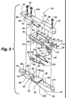
Fig. 5 is an exploded isometric of the cutting tool of the invention.
Fig. 6 is a fragmentary isometric of a cell-in-cell covering for an
architectural
opening.
Fig. 7 is an enlarged fragmentary section taken along line 7-7 of Fig. 6.
Fig. 8 is an enlarged fragmentary transverse section through the bottom rail
and the lowermost cell of the covering shown in Fig. 7.
Fig. 9 is a fragmentary isometric of a cell-in-cell fabric material showing
the
cutting tool of the present invention being advanced into the uppermost and
lowermost cells of the fabric.
Fig. 10 is a fragmentary section similar to Fig. 9 showing the cutting tool
partially advanced into the uppermost cell of the fabric.
Fig. 11 is a transverse section taken along line 11-11 of Fig. 10 through the
leading end of the cutting tool and one double cell as found in the fabric of
Fig. 6.
Fig. 12 is an enlarged section taken along line 12-12 of Fig. 11.
Fig. 13 is an isometric similar to Fig. 10 with the cutting tool having been
advanced further into the uppermost double cell of the fabric and showing an
anchor
bar in position for advancing the cutting tool through the uppermost cell.
5
CA 02676262 2009-07-22
WO 2008/098238 PCT/US2008/053559
Fig. 14 is an isometric similar to Fig. 13 with the anchor bar engaged with
the
cutting tool for advancing it through the uppermost double cell.
Fig. 15 is an isometric similar to Fig. 14 with the cutting tool being
advanced
out of the downstream end of the uppermost cell by the anchor bar.
Fig. 16 is an isometric looking downwardly from the rear on a second
embodiment of the tool shown in Figs. 1-15.
Fig. 17 is a right side elevation of the tool shown in Fig. 16.
Fig. 18 is a vertical section taken along line 18-18 of Fig. 16.
Fig. 19 is a horizontal section taken along line 19-19 of Fig. 16.
Fig. 20 is an exploded isometric looking upwardly from the front of the
cutting
tool of Fig. 16.
Fig. 21 is a fragmentary isometric showing the tool aligned with an upper cell
of a cell-in-cell shade preparatory for cutting the upper inner cell of the
shade.
Fig. 22 is a fragmentary isometric similar to Fig. 21 with the tool having
been
initially inserted into the upper inner cell of the shade.
Fig. 23 is an enlarged vertical section taken along line 23-23 of Fig. 22.
DESCRIPTION OF THE PREFERRED EMBODIMENT
The cutting tool 20 of the present invention is best seen in Figs. 1-5 to
comprise a two-piece main body 22 having a lateral extension member 24
securable
thereto and guide arms 26 secured to the lateral extension member on opposite
sides of the main body. A pair of cutting blades 28 are positioned between the
two
halves 22 and 22b of the main body and confined by the lateral extension
member
so cutting edges 30 of the cutting blades are directed toward the leading end
of the
main body. As will be discussed later, the assembled cutting tool is adapted
to be
6
CA 02676262 2009-07-22
WO 2008/098238 PCT/US2008/053559
advanced through a double cell of a cell-in-cell fabric for an architectural
covering so
the cuffing blades severe the inner cell while leaving the outer cell intact
whereby an
anchor bar used to secure the double-cell fabric to a top rail or bottom rail
of the
covering can be desirably inserted into the severed cell.
As is probably best appreciated by reference to Fig. 5, each half
segment 22a and 22b of the main body is substantially identical having a
forwardly
and downwardly tapered leading end 32 and a squared off trailing end 34. Each
half
segment of the main body has a relatively flat inner surface 36 in which
notches are
formed and a contoured outer surface 38 with the leading end of the body
having a
maximum dimension from top to bottom that is greater than the trailing end.
When
the half segments of the main body are secured together, as with fasteners 40
passing through aligned passageways 42 therethrough (as seen in Fig. 2), the
main
body has a transverse peripheral dimension that varies along the length of the
main
body. By transverse peripheral dimension, it is meant the distance along the
periphery of the object in a transverse plane.
With reference again to Fig. 5, it will be seen the generally flat inner face
or
surface 36 of each main body segment 22a and 22b has a first flat surface 44
at the
leading end thereof, an adjacent first shallow recess 46 immediately
rearwardly
thereof and a relatively deep recess 48 rearwardly of the first shallow recess
with the
deep recess having an integral relatively wide plate 50 positioned therein to
define
channels 52 and 54 in front and behind the wide plate respectively.
Immediately
rearwardly of the deep recess is a second flat surface 56 that is coplanar
with the
first flat surface 44 at the leading end of the half segment and rearwardly of
the
second flat surface is a second shallow recess 58 that opens through the
trailing end
of the half segment. Each half segment has an identical relatively flat inner
7
CA 02676262 2009-07-22
WO 2008/098238 PCT/US2008/053559
surface 36 so that when the inner surfaces 36 are placed in confronting
relationship
the two half segments define transverse channels or pockets for purposes to be
described hereafter.
The lateral extension element or member 24 is a generally U-shaped element
that opens forwardly so as to have two side arms 60 interconnected at a base
or
trailing end by a relatively broad block-like portion 62. The leading end of
each side
arm is tapered defining a relatively narrow vertical leading edge 64 and an
inwardly
and rearwardly tapering inner surface 66. The lateral extension element is
designed
to have its base 62 seated in the relatively deep channel 54 rearwardly of the
wide
plate 50 in each half segment of the main body so as to be confined therein
when
the half segments 22a and 22b are connected in confronting relationship. When
properly seated and confined within the main body, the side arms 60 are spaced
slightly from the sides 68 of the main body.
The guide arms 26 as seen in Fig. 5 are adapted to be secured to the leading
end of each side arm 60 with each guide arm having an outer plate-like portion
70
with a passage 72 therethrough for receipt of a fastener 74 that can be
advanced
through the passage and into the associated leading end of a side arm. The
guide
arm has a forked rearwardly projecting extension 76 that is also angled
inwardly so
the forked ends of the guide arms are in engagement with an associated side 68
of
the main body when the guide arms are secured to the side arms. The guide arms
are made of a somewhat flexible material so that upon adequate pressure, they
can
be flexed away from the side 68 of the main body for a purpose to be described
hereafter.
The exposed face 78 of each wide plate 50 is coplanar with the relatively
shallow adjacent first recess 46 in its associated half segment 22a or 22b of
the main
8
CA 02676262 2009-07-22
WO 2008/098238 PCT/US2008/053559
body 22 and when the half segments are placed in confronting relationship, as
possibly best seen in Fig. 2, a pocket or channel 80 is defined between the
wide
plates and the first shallow recesses to define a seat for the pair of cutting
blades 28
as seen in Fig. 5. The cutting blades have a substantially longitudinally
extending
first edge 82 which is adapted to be abutted against the same adjacent edge of
the
other cutting blade and the outwardly and rearwardly tapered sharpened cutting
edge 30 opposite the first edge that extends over halfway along the length of
the
cutting blade. At the rearmost extent of the sharpened edge, the cutting blade
has a
second longitudinally extending side edge 84. The longitudinally extending
side
edges 82 and 84 terminate in a perpendicular rear edge 86. The cutting blades
are
adapted to be placed in abutting side-by-side relationship between the wide
plates 50 and the first shallow recesses 46 of the two main body half segments
with
the rear edge 86 of each blade abutted against the base 62 of the lateral
extension
element 24 as seen best in Fig. 2. The width of the blades are such that the
cutting
edges extend from a point inwardly of the sides 68 of the main body to a point
contiguous with the associated side arm 60 of the lateral extension element.
The
second longitudinal side edge 84 of each cutting blade is abutted against the
adjacent side arm so the cutting blades are held positively in position
between the
side arms of the lateral extension element, the base of the lateral extension
element,
the wide plates and the first shallow recesses of the main body half segments.
The cutting edges 30 of each cutting blade 28 extend into the forked rear
extension 76 of the guide arms 26 so that each leg 88 in a fork is overlying
or
underlying a cutting blade. The cutting edge of the cutting blade will also be
appreciated to extend between the side 68 of the main body and the inner side
of a
side arm 60 so as to fill that space whereby anything passing through that
space in a
9
CA 02676262 2009-07-22
WO 2008/098238 PCT/US2008/053559
front to rear direction relative to the main body 32 will engage the cutting
edges of
the cutting blades. As will also be appreciated, the guide arms are tapered so
as to
encourage anything approaching the guide arms between their leading end and
the
side of the main body to pass between the guide arms and the main body and
engage a cutting edge of a blade.
With reference to Fig. 6, a covering 90 for an architectural opening in which
the cutting tool 20 of the present invention finds use is shown as including a
head
rail 92, which can be fixed in an architectural opening in any conventional
manner,
and a vertically movable but horizontal bottom rail 94 that extends parallel
with the
head rail. The bottom rail is affixed in a manner to be described hereafter to
the
lowermost cell 96a in the dual cell fabric extending between the head rail and
the
bottom rail while the uppermost dual cell 96b is attached to the head rail in
a manner
to be described hereafter.
A dual cell fabric 98, which is also referred to as a cell-in-cell fabric,
used in
the covering 90 is comprised of a plurality of concentric dual cells 96 that
are
connected to an adjacent cell along a top and bottom side. Each dual cell of
the
fabric is made of a flexible material such as a fabric material that is
transversely
collapsible but retains its configuration along its length when suspended
between the
head rail 92 and the bottom rail 94. The dual cells consist of an outer cell
100 having
pleated front and rear edges 100a and 100b respectively and a smaller
concentric
inner cell 102 having corresponding front and rear pleated edges 102a and
102b,
respectively, spaced inwardly from the front and rear edge of the outer cell,
as best
appreciated by reference to Fig. 7. Both the inner and outer cells are
symmetric
about a horizontal plane intersecting a central longitudinal axis of the cells
as well as
about a similar vertical plane. Each dual cell can be formed in accordance
with the
CA 02676262 2009-07-22
WO 2008/098238 PCT/US2008/053559
teachings in U.S. Patent No. 6,345,486, issued Feb. 12, 2002, which is of
common
ownership with the present application and the disclosure of which is hereby
incorporated by reference.
As best appreciated by reference to Fig. 7, both the head rail 92 and the
bottom rail 94 have confronting inwardly opening longitudinally extending
channels 104 formed therein which are adapted to receive edges of a
substantially
rectangular anchor bar 106 which has a lateral dimension slightly greater than
the
spacing between the channels 104 of the head rail and the bottom rail and
having a
length substantially commensurate with the length of the head rail and bottom
rail.
The anchor bar, as best appreciated by reference to Figs. 7 and 8, is inserted
into
the uppermost cell 96b and the lowermost cell 96a of the ceilular fabric 98
with the
uppermost cell, as mentioned previously being connected to the head rail 92
and the
lowermost cell being connected to the bottom rail 94. The anchor bar is
inserted
longitudinally into the uppermost and lowermost cells so as to laterally fill
the cell and
retain the cell between the confronting channels 104 of the head rail or
bottom rail as
the case may be. The anchor bar is slightly flexible so as to be biased within
the
confronting channels to provide positive retention of the fabric 98 to the
head rail and
bottom rail. In this manner, it will be appreciated the cellular fabric
material is
suspended from the head rail and extends to the bottom rail with the
interconnected
cells 96 of the fabric being parallel with the head rail and bottom rail. As
is
conventional in retractable coverings, one or more lift cords 108 extend from
an
accessible position outside the head rail, through the head rail and
vertically
downwardly through each cell for attachment to the bottom rail so when the
lift cords
are manually pulled, the lift cords raise the bottom rail toward the head
rail. Of
course, by manually allowing the lift cords to rise, where they are held by an
11
CA 02676262 2009-07-22
WO 2008/098238 PCT/US2008/053559
operator, the bottom rail is allowed to drop by gravity in moving away from
the head
rail. Conventional cord locks (not seen) are provided in the head rail for
securing the
lift cords at any desired position so the fabric can be moved between a fully
retracted
position where the cells are collapsed adjacent to the head rail to a fully
extended
position where the cells are transversely open and the bottom rail is
maximally
spaced from the head rail as shown in Fig. 7.
As can be appreciated by reference to Figs. 7 and 8, it is desirable that the
flattened width of an outer cell 100 with the anchor bar 106 inserted
therethrough is
substantially equal to the spacing between the confronting channels 104 in the
head
rail and the bottom rail so the uppermost 96b or lowermost 96a cell as the
case may
be is positively retained in the head rail or bottom rail, respectively. This
being the
case, it is necessary to longitudinally cut the inner cell 102 in the
uppermost and
lowermost dual cells as the innermost cell due to its smaller width, would
prevent the
anchor bar from being inserted longitudinally into the outer cell in a
position to fill the
outer cell in a flattened condition. The cutting tool 20 of the present
invention has
been designed to cut the inner cell without damaging the outer cell so the
anchor bar
can be inserted into the uppermost and lowermost cells to connect these cells
with
the associated head rail or bottom rail as described above.
With reference to Fig. 9, it will be seen the cutting tool 20 is inserted into
either the uppermost 96b or lowermost 96a cell with the leading end 32 of the
cutting
tool. The transverse peripheral dimension of the main body at the leading end
of the
cutter has a maximum transverse peripheral dimension which is, as appreciated
by
reference to Fig. 11, commensurate with the transverse peripheral dimension of
the
inner cell 102 of the dual cell in which the cutter is being inserted. In this
manner,
the inner cell is drawn tightly around the transverse peripheral dimension of
the
12
CA 02676262 2009-07-22
WO 2008/098238 PCT/US2008/053559
cutter tool at its maximum transverse peripheral dimension so opposite sides
of the
inner cell are fed between the sides 68 of the main body and the leading end
of a
guide arm 26 as the tool is inserted further and longitudinally into the dual
cell. As
will be appreciated, as the then confronting edge 103 (Figs. 11 and 12) of the
inner
cell is advanced longitudinally along the length of the cutter with the cutter
being
advanced through the dual cell, the confronting edge is presented to the
sharpened
edges 30 of the cutting blades 28 which cleanly and dependably severe the
inner cell
along opposite longitudinal sides of the cell. As will be appreciated, as the
tool is
fully advanced through the dual cell, the inner cell is totally severed along
opposite
sides thereby enabling an anchor bar 106 to be inserted into the dual cell in
engagement with the outer concentric cell 100.
As will be appreciated further from Fig. 11, the lateral extension member 24
will hold the outer cell 100 in a fully expanded condition where it is
protected from the
cutting edges 30 of the cutting blades by the side arms 60 so the outer cell
is
undamaged as the cutting tool is advanced longitudinally through a dual cell.
This
relationship is also illustrated in the sectional view in Fig. 12. It might,
therefore, be
said the cutting tool, at the maximum a transverse peripheral dimension of the
leading end thereof where it overlaps the lateral extensions, defines a
hypothetical
enclosure having a transverse peripheral dimension substantially the same as
the
transverse peripheral dimension of the outer cell 100. This hypothetical
enclosure
would be identical to the cross section of the outer cell as seen in Fig. 11.
As will be appreciated from the earlier description, the transverse peripheral
dimension of the main body 22 of the cutter tool is smaller at the trailing
end than it is
near the leading end so that after the inner cell 102 has been cut by the
cutting
13
CA 02676262 2009-07-22
WO 2008/098238 PCT/US2008/053559
blades 28, the dual cell will freely pass over the smaller transverse
peripheral
dimension of the cutter tool.
As will be appreciated from the previous description of the cutting tool 20,
the
trailing end 34 has the second relatively shallow confronting recesses 58
which
define a pocket 112 therebetween opening through the trailing end of the tool
as
seen best in Fig. 2. This pocket can be utilized to advance the cutter tool
through a
dual cell being treated and at the same time position the anchor bar 106
within the
cell. With reference to Figs. 13-15, it will be seen the cutter tool has been
advanced
into one open end of the uppermost dual cell 96b so the pocket 112 is directed
rearwardly and exposed. The anchor bar can then be inserted into the pocket as
shown in Fig. 14 and by pushing the anchor bar, the cutter tool is advanced
through
the cell thereby severing the innermost cell 102 along its opposite sides and
desirably positioning the anchor bar within the cell. Fig. 15 illustrates the
cutter tool
exiting the uppermost dual cell and with the anchor bar substantially fully
inserted
into the uppermost dual cell. Once the cutter tool is fully forced through the
uppermost dual cell, the anchor bar is positioned within the uppermost dual
cell in a
manner that retains the uppermost cell in a generally flattened state.
The steps illustrated in Figs. 13-15 can be executed so as to position the
anchor bar 106 within the uppermost dual cell 96b and then the anchor bar with
the
dual cell mounted thereon advanced longitudinally along the head rail 92 so
the side
edges of the anchor bar, with the outer concentric cell disposed thereon, are
positioned between the confronting channels 104 so the uppermost cell is
secured to
the head rail. Of course, the same procedure is followed for anchoring the
lowermost dual cell 96a to the bottom rail 94.
14
CA 02676262 2009-07-22
WO 2008/098238 PCT/US2008/053559
A second embodiment 120 of the cutting tool of the present invention is
shown in Figs. 17-23 and will be seen to be functionally and structurally very
similar
to the first-described embodiment 20 except the lateral extension member 24 of
the
first embodiment has been made integral with the two halves of the main body
as will
be described in detail hereafter. In addition, one of the halves of the main
body at its
leading end has been made flexible and resilient to improve tightening or
stretching
of the inner cell of the dual-cell fabric 98, which facilitates improved
cutting of the cell
with the tool. Due to the close similarity of this embodiment with the first-
described
embodiment, like parts have been given like reference numerals.
The tool 120 of the second embodiment is probably best seen in Fig. 20 to
comprise an upper main body half 122 and a lower main body half 124, which are
identical except to an extent to be pointed out hereafter and, accordingly,
only one of
the halves will be described in detail. Each main body half can be seen to
have a
tapered leading end 126 and a squared off trailing end 34. Each half or haif
segment
of the main body has a relatively flat inner surface 128 in which notches are
formed
and a contoured outer surface 130 with the leading end 126 of the body being
thicker
from top to bottom than the trailing end 34. When the half segments of the
main
body are secured together, as with fasteners 132 passing through aligned
passageways 134 and into blind holes 136 (as seen in Fig. 18), the main body
has a
transverse peripheral dimension that varies along the length of the main body.
Referring again to Fig. 20, it will be seen the generally flat inner face or
surface 128 of each main body half segment 122 and 124 has a first flat
surface 138
at the leading end thereof and an adjacent first shallow recess 140
immediately
rearwardly thereof with the first shallow recess being relatively narrow
nearer the
leading end of the half segment at 142 and relatively wide at a trailing end
thereof at
CA 02676262 2009-07-22
WO 2008/098238 PCT/US2008/053559
144. Rearwardly from the trailing end of the first shallow recess 140, there
is a
second flat surface 146 that is coplanar with the first flat surface 138 and
rearwardly
of the second flat surface is a second shallow recess 58 that opens through
the
trailing end 34 of the half segment. Each half segment has an identical
relatively flat
inner surface so that when the inner surfaces are placed in confronting
relationship,
the two half segments define transverse channels or pockets at the first 140
and
second 58 shallow recesses for purposes to be described hereafter.
The second flat surface 146 at its leading end has outwardly directed lateral
extensions 148 of the main body. Each lateral extension has a transverse
component 150 and a forwardly directed component 152. The components are
adjacent to trailing and lateral sides of the relatively wide area 144 of the
first shallow
recess 140. The forwardly directed components or arms 152 extend forwardly of
the
wide area 144 and are spaced from the sides 154 of the main body half where
the
first shallow recess 140 is relatively narrow. The leading ends of the arms
152 are
tapered inwardly toward the leading end of the main body half and have a
relatively
narrow vertically extending leading edge 156. A gap 158 is defined between the
leading edge of each arm 152 and the sides of the main body half. At the
leading
edge of each arm, a laterally extending internally threaded hole 160 is
provided for a
purpose to be described hereafter. The transverse component 150 and forwardly
extending component or arms 152 of each lateral extension 148, when placed in
confronting relationship with the corresponding parts of the other main body
half,
serve a purpose identical to the lateral extension element or member 24 of the
first-
described embodiment. As probably best appreciated by reference to Figs. 19
and
20, the first shallow recess 140 is adapted to receive two cutting blades 28
identical
to those of the first-described embodiment.
16
CA 02676262 2009-07-22
WO 2008/098238 PCT/US2008/053559
Guide arms 161 as seen in Fig. 20 are adapted to be secured to the leading
end of each forwardly extending arm 152 with each guide arm having an outer
plate-
like portion 70 with a pair of passages 164 therethrough for receipt of
fasteners 166
that can be advanced through an associated passage 164 and into an associated
internally threaded hole 160 of each forwardly extending arm. The guide arm
has a
forked rearwardly projecting extension 76 identical to that of the guide arms
26 in the
first-described embodiment that is also angled inwardly so the forked ends of
the
guide arms are in engagement with an associated side of the main body when the
guide arms are secured to the forwardly extending arms. The guide arms are
made
of a somewhat flexible material so that upon adequate pressure, they can be
flexed
away from the side of the main body.
The passages 134 (Fig. 20) are provided through the lower half segment 124
for receipt of the fasteners 132 with the upper half segment 122 having the
blind
threaded holes 134 for receipt of the fasteners so that the two half segments
can be
secured together with the cutting blades 28 positioned therebetween. After the
half
segments are secured together, the guide arms 160 can be secured to the
forwardly
extending arms 152 to fully assemble the cutting tool.
As seen in Figs. 16, 17, 18, and 20, an enlarged head 168 forming part of the
leading end 126 of the upper half segment 122 has a horizontal slot 170 formed
therein from the rear end of the head toward the leading end of the head. Each
half
of the main body is made of a resilient but somewhat rigid material so that
this slot
allows the head at the leading end of the main body to flex downwardly while
being
biased into a neutral position of Figs. 16-18 and 20. In this manner, when the
cutting
tool is used as described in connection with the first-disclosed embodiment,
the
resilient head 168 of the tool can actually hold the inner cell 102 of the
cell-in-cell
17
CA 02676262 2009-07-22
WO 2008/098238 PCT/US2008/053559
fabric 98 in a taut or stretched condition so the cutting blades 28 are
efficient in
cutting the sides of the inner cell of the fabric.
Figs. 21 and 22 show the cutting tool 120 being positioned and then advanced
into the upper cell of a cell-in-cell fabric 98 with Fig. 23 showing the tool
holding the
inner cell 102 in a taut or stretched condition while the cutting blades sever
the
innermost cell along horizontal lines into identical upper and lower halves.
It will be appreciated from the above that a cutter tool for severing the
inner
concentric cell of a dual cell used in a cell-in-cell covering for a
architectural opening
has been described which conveniently not only severs the inner cell so that
an
anchor bar can be placed in engagement with the outer cell but does so in a
manner
so the anchor bar is placed in the outer cell simultaneously with the cutting
of the
inner cell. Accordingly, a task, which formerly was very time consuming, can
now be
done very expeditiously and dependably.
Although the present invention has been described with a certain degree of
particularity, it is understood the disclosure has been made by way of
example, and
changes in detail or structure may be made without departing from the spirit
of the
invention as defined in the appended claims.
18