Note: Descriptions are shown in the official language in which they were submitted.
CA 02676351 2009-07-23
1
WO 2007/085859
PCT/GB2007/000292
PARAMETRIC GENERATION USING INTERSECTING CAVITIES
The present invention relates to parametric generation of electromagnetic
radiation in
which a non-linear material when pumped by light energy produces radiation of
different wavelengths to that of the pump energy, and in particular radiation
that is
outside the normally accepted transparency range of the non-linear material.
BACKGROUND OF THE PRESENT INVENTION
Parametric devices are flexible and convenient sources of widely-tunable
coherent
radiation, encompassing all time-scales from the femtosecond pulse to the
continuous-
wave. In these, a coherent beam of electromagnetic radiation referred to as
the pump
wave is used to stimulate a non-linear process in a non-linear (optical)
material,
resulting in the division of the energy/power in the coherent pump into two
generated
waves, typically referred to as the signal and idler waves. The signal wave is
usually
defined as the wave providing the useful output from the device, although that
is not
invariably the case. In the present application, the signal wave has the
longer
wavelength of the two generated waves.
Parametric devices can operate in a variety of configurations including
amplifiers,
oscillators and generators. In a parametric amplifier an intense coherent pump
wave is
made to interact with the non-linear material to produce amplification at the
signal
and idler wavelengths. A parametric oscillator uses a parametric amplifier
inside a
cavity resonant at one or both of the signal and idler waves. In this case,
the
signal/idler waves are either self-starting from noise/parametric fluorescence
or the
cavity is injection seeded by a suitable source operating at the signal/idler
wavelength.
Oscillators that are resonant at only one of the signal and idler wavelengths
are
referred to as being singly-resonant, whilst those that are resonant at both
are referred
to as doubly-resonant oscillator. As is well established in the literature the
doubly-
resonant oscillator has the advantage of a significantly lower oscillation
threshold in
terms of the pump power/energy required to bring the oscillator into
oscillation
compared to the singly-resonant oscillator. However, the doubly-resonant
oscillator
has serious disadvantages in terms of the attainment of smooth and continuous
tuning
of the signal/idler waves.
CA 02676351 2009-07-23
WO 2007/085859 2
PCT/GB2007/000292
Parametric generators generate signal/idler waves by the interaction of an
intense
pump wave with a non-linear material to parametrically produce these two other
waves. No cavity is provided for these down-converted waves since the
parametric
gain in this case is sufficiently high as to allow adequate transfer of
energy/power to
these waves with only non-resonant single (or multiple) passing of the signal
and/or
idler waves through the non-linear material. Again in this case the signal
and/or idler
waves are self-starting from noise/parametric fluorescence or the generator is
injection seeded by a suitable source operating at the signal and/or idler
wavelengths.
There is considerable interest in extending the spectral coverage of
parametric
devices. This is because they are often used as sources of coherent
electromagnetic
radiation in spectral regions either not covered by any other sources, or
where a single
parametric-wave source is capable of replacing a number of sources that would
otherwise be needed in order to provide the spectral coverage required.
However, a
serious limitation encountered in attempting to extend the spectral coverage
of
parametric generation to new regimes of the electromagnetic spectrum is the
detrimental effect of absorption within the non-linear material of one or more
of the
three waves involved in the non-linear interaction. Indeed, the spectral
coverage
attainable with a particular parametric generation scheme is often determined
by the
onset of such absorption rather than by the non-linear or phase-matching
characteristics of the non-linear material. Hence, it follows that elimination
of such a
restriction would result in improved spectral coverage attainable through the
parametric generation process.
One solution to the problem of absorption is to employ a configuration of
interacting
waves such that the wave subject to excessive absorption exits the non-linear
material
as rapidly as possible after its generation. This wave is usually, but not
invariably, the
signal wave. One method for doing this is based on using non-collinear phase
matching in such a way as to cause the wave subject to absorption to rapidly
walk out
from the non-linear material in a direction that is substantially lateral to
the
propagation direction of the pump wave. This is illustrated in Figurel, which
shows
the geometry of the interacting pump 1, idler 2 and signal 3 waves in a non-
linear
material 4. Figure 2 shows the phase-matching process through a so-called k-
vector
CA 02676351 2015-02-10
3
diagram where kp, ki, ks are the wave vectors of the pump, idler and signal
respectively within the non-linear material, angle 0 is the angle subtended by
the
pump 1 and idler 2 waves and angle 4) the angle subtended by pump wave 1 and
signal
wave 3. By altering the angle 0 between the pump 1 and idler 2 waves, the
signal
wave can be rapidly tuned over a wide range.
To maintain the necessary non-linear interaction between the pump wave 1 and
the
idler wave 2 of Figures 1 and 2, they must be of sufficient radial
(transverse) extent to
maintain overlap between them throughout the length of the non-linear
material. The
parametric gain scales with the radial extent of these beams. As a consequence
of the
limitation placed on the interaction between the three waves due to the
lateral walk-
off of the signal wave, the radial extent of the beams needs to be of the
order of the
absorption length of the signal wave in the non-linear medium in order to
optimise the
gain experienced by the idler wave 2.
Examples of the technique of Figures 1 and 2 are described in the articles
"Efficient,
tunable optical emission from LiNb03 without a resonator", by Yarborough et
al,
Applied Physics Letters 15(3), pages 102-4 (1969); "Coherent tunable THz-wave
generation from LiNb03 with monolithic grating coupler", by Kawase et al,
Applied
Physics Letters 68(18), pages 2483-2485 (1996); and "Terahertz wave parametric
source" by Kawase et al, Journal of Physics D: Applied Physics 35(3), pages R1-
14
(2002).
A problem with the arrangement of Figures 1 and 2 is that because of the
reduced
interaction between the three waves, the oscillation threshold is increased
compared to
conventional devices where the waves are all collinear. This has the
undesirable
consequences of limiting the applicability of the technique to materials
exhibiting
high non-linear coefficients, as well as requiring pump waves of high
energy/power,
and so demanding the undesirable use of high-energy/power lasers. This latter
requirement prevents the development of compact and portable versions of these
devices, so limiting their utility.
CA 02676351 2015-02-10
4
An alternative approach to that illustrated in Figures 1 and 2 is to arrange
for the
pump 1 and idler 2 waves to propagate collinearly through the non-linear
material 4
while still maintaining the substantially lateral propagation of the signal
wave 3. This
condition of operation is effected by the use of a slant-stripe-type
periodically-poled
crystal as the non-linear material. Figure 3 illustrates this hybrid
collinear/non-
collinear phase-matching process. Figure 4 illustrates the phase-matching
process
through a k-vector diagram, in which K is the grating vector that describes
the slant-
stripe, periodically-poled non-linear crystal. Examples of this technique are
described
in co-pending international patent application PCT/GB2005/002912.
In this case, the presence of the additional vector K allows the pump .1 and
idler 2
waves to propagate collinearly within the non-linear crystal 4 while the
signal wave
exits substantially laterally as required. Indeed it'is apparent that it can
be so arranged
that the signal wave 3 propagates orthogonal to the collinear pump 1 and idler
2
waves. Having the pump 1 and idler 2 waves collinear means that common
elements
can be used such as, but not restricted to, mirrors for the guidance or
resonance of
these waves. This can simplify otherwise complicated arrangements. In
addition, the
common-path approach associated with the collinear propagation of the pump 1
and
idler 2 waves confers the advantage of enhanced geometrical/mechanical
stability.
Whilst the arrangement illustrated by Figures 3 and 4 confers some technical
advantages, because it requires the fixing of the propagation direction of the
idler
wave 2 to be collinear with the propagation direction of the pump wave 1, the
ability
to attain wide and continuous tuning of the parametric process through the use
of
angle tuning is lost.
For the purpose of minimising the external pump power required to reach
oscillation
threshold, an approach adopted in the prior art is to place the optical
parametric
oscillator within the cavity of the laser used to generate the pump wave and
in such a
way that all three waves are collinear within the non-linear crystal, an
arrangement
generally referred to as an intracavity optical parametric oscillator. Because
the non-
linear medium experiences a pump wave with the intensity associated with the
internal radiation field of the pump laser, which is generally substantially
greater than
CA 02676351 2015-02-10
the external radiation field available under optimum output coupling from the
same
pump laser, the requirements on the energy and power of the pump laser are
significantly relaxed, leading to more compact devices. Examples of this are
described
in US 3,628,186; US 5,117,126; GB 2,252,840 A; US 5,195,104; US 5,181,211; US
5 5,291,503; WO 94/24735; and EP 0 644 636 A2. However, none of the systems
described in
these allow for the rapid exit of the required signal wave from the non-linear
material,
simultaneously with wide and continuous tuning.
SUMMARY OF THE INVENTION
According to the present invention, there is provided a parametric device
having a
non-linear material for generating idler and signal waves in response to a
pump wave,
the pump, idler and signal waves being non-collinear, the device having a
cavity
resonant at the pump wavelength and which contains the non-linear material and
means for
varying the angle between the propagation directions of the pump and idler
waves.
The present invention provides a cavity for causing the pump wave to resonate.
The
device is arranged so that there is adequate spatial overlap of the pump and
idler
waves around the point of intersection. The non-linear material is placed
appropriately at this region of overlap. Means are provided for altering the
angle
between the direction of propagation of the pump and idler waves so as to
provide
broad and continuous tuning of the signal wave, whilst maintaining both the
required
degree of overlap of the pump and idler waves and the required lateral walk-
off of the
signal wave.
The idler wave direction may be defined by a cavity designed to resonate the
idler
wave. The idler wave may be allowed to define its own propagation direction
through
the nonlinear gain medium. This propagation direction may be defined by the
injection of a seeding wave at the wavelength of the idler wave into the
nonlinear gain
medium.
The pump wave cavity may contain one or more components required for the
operation of the pump laser, for example a pump wave gain medium. This is
referred
to as a pump-generating geometry.
CA 02676351 2015-02-10
6
Alternatively, the pump wave cavity may be held on resonance by means of
suitable
servo-control systems so as to resonantly enhance a pump wave generated using
a
pump laser external to the cavity, but coupled into the cavity by suitable
mode-
matching/isolating optics. This is referred to as pump enhancement geometry.
The present invention provides a system that reduces the pump power/energy
required
to reach oscillation threshold, and allows the non-linear material to
experience either
the intracavity field of the pump laser or the resonantly enhanced field of
the pump
laser, while at the same time avoiding the disadvantages of lack of angular
tuning and
lateral beam walk-off of the signal wave.
BRIEF DESCRIPTION OF THE DRAWINGS
Various aspects of the invention will now be described with reference to the
accompanying drawings, of which:
Figure 1 shows the geometry of an interacting pump, idler and signal waves in
a
non-linear material.
Figure 2 shows the phase-matching process through a so-called k-vector
diagram.
Figure 3 illustrates a hybrid collinear/non-collinear phase-matching process.
Figure 4 illustrates a phase-matching process through a k-vector diagram.
Figure 5 is a schematic diagram of a parametric oscillator based on aa pump-
generating geometry with intersecting pump wave and idler wave cavities;
Figure 6 is a schematic diagram of a parametric oscillator based on a pump-
enhancement geometry with intersecting pump wave and idler wave cavities;
Figure 7
is a schematic diagram of a parametric generator based on a pump-generating
geometry in which the idler wave builds up a coherent signal from noise in a
single
pass of the non-linear material;
Figure 8 is a schematic diagram of a parametric generator based on a pump-
generating geometry in which the idler wave is injection seeded; and
Figure 9 is a schematic diagram of a particular parametric oscillator for
generating terahertz radiation, given by way of example only.
CA 02676351 2015-02-10
6a
DETAILED DESCRIPTION OF THE DRAWINGS
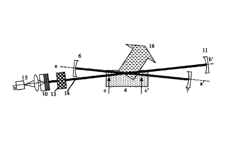
Figure 5 shows an intersecting cavity parametric oscillator. This has a non-
linear
medium 4 located within an idler wave cavity that is defined by two mirrors 6
and 7
and a pump wave cavity that is defined by mirrors 10 and 11. Within the pump
wave
cavity is a gain medium 13 for the pump wave, and means for controlling the
pump
wave 14, such as, for example a Q-switch and/or frequency controller. This is
a
configuration in which the pump wave is generated within the pump cavity. This
CA 02676351 2009-07-23
7
wo 2007/085859
PCT/GB2007/000292
configuration is generally referred to as a pump-generating geometry. The gain
medium 13 is excited by an external primary pumping source 15, such as laser
diodes
incorporating suitable coupling optics. The optical axis aa' of the idler wave
cavity is
arranged to intersect the axis bb' of the pump wave cavity, so that
significant overlap
of the two waves occurs in the region cc' within the non-linear material 4.
Means are
provided for varying the angle between the optical axes aa' and bb'. For
example,
any suitable mechanical arrangement could be used.
In use, the signal wave 16 of Figure 5 exits laterally from the overlap
region, thereby
to avoid absorption. The wavelength of the signal wave 16 can be tuned merely
by
varying the angle between optical axes aa' and bb'. Hence, the oscillator
allows for
the rapid exit of the required signal wave from the non-linear material,
whilst
simultaneously providing wide and continuous tuning.
Figure 6 shows another parametric device that has a non-linear medium 4
located
within an idler wave cavity that is defined by two mirrors 6 and 7 and a pump
wave
cavity 17 that is defined by mirrors 18 and 19. In this case, only the non-
linear
medium 4 is located in the pump cavity. The pump cavity 17 is held on
resonance
with the pump wave provided by an external pump laser 20 through the use of
appropriate mode matching and isolation optics 21 and a servo-control system
22.
This configuration is generally referred to as a pump-enhancement geometry. In
this
case, the optical axis aa' of the idler wave cavity intersects the optical
axis of the
pump-enhancement cavity 17, in such a manner that significant overlap of the
two
waves occurs in the region cc' within the non-linear material 4.
In use, the signal wave 16 of Figure 6 exits laterally from the overlap
region, thereby
to avoid absorption. The wavelength of the signal wave can be tuned merely by
varying the angle between optical axes aa' and bb'. Hence, the oscillator
allows for
the rapid exit of the required signal wave from the non-linear material,
whilst
simultaneously providing wide and continuous tuning.
Figure 7 shows a parametric generator that is similar to Figure 5. However, in
this
case the idler cavity is removed and the idler wave builds up as a coherent
signal from
noise in a single pass of the non-linear material assuming a propagation
direction
CA 02676351 2009-07-23
8
wo 2007/085859
PCT/GB2007/000292
appropriate to maximum down-conversion. The propagation direction, and hence
the
tuning of the device, is determined by the balance between the constraints
placed on
the nonlinear conversion process such as energy conservation, phase-matching,
parametric gain, signal wave absorption, and overlap of idler and pump waves.
By
varying the angle between the propagation directions of the pump and idler
waves,
this device can be tuned.
Figure 8 shows another parametric generator that is similar to Figure 7. This
is an
injection-seeded parametric generator in which the idler cavity is replaced by
an
injected wave generated by an injection seeder 23, and arranged so as to
propagate
along the axis previously associated with the idler cavity and with a
wavelength
appropriate to the wavelength of the idler wave supported formerly by the
idler cavity.
The wavelength and direction of propagation of the idler wave produced by
parametric generation is determined by the direction of propagation and
wavelength
of the injected wave. Further the idler wave grows by amplification of the
coherent
injected wave rather than by amplification of noise as in Figure 7. Therefore,
the
single-pass gain required for efficient down-conversion to take place is
reduced. In
this case, the device is fully tunable by suitably altering the propagation
direction of
the injected wave in step with changing its wavelength. Injection of a narrow
linewidth wave can result in line-narrowing of both the signal and idler waves
generated through down conversion.
Figure 9 shows an example of a parametric oscillator with an intersecting
cavity
geometry, specifically arranged for the purpose of generating THz radiation
(signal
wave). The pump wave cavity is formed by mirrors Ml and M2, physically
separated
by 37cm, and includes the laser gain medium (LG), polarisation control optics
(QW,
QS and POL) and the parametric oscillator nonlinear crystal (NL). The laser
gain
medium is a neodymium yttrium aluminium garnet crystal (Nd:YAG) with
dimensions 4mm diameter x 7mm length and is excited by a quasi-continuous-wave
laser-diode (QCW-LD) as the external pump source. The QCW-LD is operable at up
to 100Hz pulse repetition rate with a pulse duration of up to 500 sec and peak
power
in excess of 100W (50mJ per pulse).
=
CA 02676351 2009-07-23
9
wo 2007/085859
PCT/GB2007/000292
The output from the QCW-LD is fibre delivered and coupled to the laser gain
medium
via a pair of aspheric lenses (AL). A first aspheric lens, with numerical
aperture
consistent with the fibre output (NA 0.22), serves to collimate the fibre
output while
the second forms an image of the fibre exit aperture (close to 1:1 object-
image ratio)
in the Nd:YAG crystal. The polarisation state of the resonant pump wave is
determined by the insertion in to the pump wave cavity of an air spaced cube
polariser
(POL). In order to achieve the desired peak power in the pump wave, the pump
laser
is Q-switched through the insertion of a quarter-waveplate (QW) and electro-
optic Q-
switch (QS) based on deuterated potassium di-hydrogen phosphate (KD*P). The
action of these elements in association with the polariser follows a standard
mode of
operation. In the experimental system a pump pulse duration, in the absence of
any
parametric generation process, of typically 3Onsec is achieved and at the
maximum
QCW-LD excitation energy the pump pulse energy is greater than 5mJ.
The mirrors forming the pump laser cavity comprise M1, which is a high
reflector
(>99.8%R @ 1064nm) coating applied directly to the rear face of the Nd:YAG
crystal
(this being a dichroic coating also transmitting the 808nm QCW-LD excitation
light),
and M2, which is a partial reflector coating (R-90% @ 1064nm) applied to a
plane
mirror substrate. This latter mirror is not for the purpose of output coupling
since the
intention is to maintain the highest intracavity power possible consistent
with the
avoidance of optical damage. While typically transmissions of the order of 5-
10% are
utilised in practice resulting in intracavity powers of the order of' 10 to 20
times
greater than the output power attainable under optimised output coupling,
higher
enhancements are possible, but limitation to the above values is consistent
with the
avoidance of optical damage, and the requirement to monitor reliably the
intracavity
power. The modal (spatial) quality of the pump wave in this plane-plane
resonator is
then determined by a combination of thermal lensing, gain guiding and soft
aperturing
by the extent of the excited volume in the laser gain medium, the combined
effect of
which result in a near diffraction limited pump mode. All other optical
surfaces in the
pump wave cavity are anti-reflection coated at the pump wave wavelength of
1064nm.
The nonlinear crystal NL is magnesium oxide doped lithium niobate (MgOliNb03)
and has an aperture in the xz-plane of dimensions 5mm x 5mm, as seen by the
pump
and idler waves, and length along the x-axis of 50mm. The crystal is oriented
such
CA 02676351 2009-07-23
wo 2007/085859 10
PCT/GB2007/000292
that the electric vectors of the pump, idler and signal waves lie along the z-
axis, and
propagation of the pump wave is along the x-axis. The parametric oscillator
cavity is
formed by the plane mirrors M3 and M4, which are respectively a high reflector
and a
partial reflector (R-98%) at the idler wavelength. It is convenient that as
the idler
wavelength is close to the pump these can be standard Nd laser cavity mirrors.
The mirrors M3 and M4 are set in adjustable mirror mounts for ease of
alignment, but
notably these mounts are located on the ends of a common rotatable bar centred
above
the nonlinear crystal to allow easy angular adjustment of the idler cavity
axis relative
to the pump wave, and hence tuning of the signal/idler wavelengths through the
non-
collinear phasematch geometry. The physical length of the idler cavity is 13cm
and
forms an intersecting cavity with the pump wave resonator, where the central
point of
intersection is within the nonlinear crystal. Ideally the idler cavity would
be made
shorter. However, it is constrained by the need for the pump and idler waves
to be
physically separated so that the idler cavity mirrors do not impede the pump
wave.
The highly non-collinear phasematch geometry, as it relates to the generated
signal
(THz) wave, results in the THz wave exiting the nonlinear crystal through a
side face.
The 5mm x 50mm side faces of the nonlinear crystal having their normal
perpendicular to the crystallographic z-axis are then fabricated with a good
optical
polish. Due to the high refractive index of MgO:LiNb03 at THz wavelengths (-
5.2),
the total internal reflection angle for a crystal-air interface is just around
11-degrees,
as measured from the normal to the interface.
In this non-collinear phasematch geometry of Figure 9, the THz wave is
incident at an
angle of around 30-degrees and hence would be totally internally reflected and
not
output coupled. To circumvent this problem a prismatic output coupler is used.
In this
case prisms fabricated from silicon (refractive index ¨3.2) are placed against
the
polished face of the lithium niobate crystal increasing the total internal
reflection
angle at the now crystal-silicon interface to around 38-degrees and hence
allowing
output coupling. The prismatic form of the silicon allows near normal
incidence of
the THz wave at the outer surface of the prisms. Fresnel reflection from this
surface
remains significant at this time (-27%), but could be reduced in the future by
the
application of an index matching layer.
CA 02676351 2009-07-23
11
WO 2007/085859
PCT/GB2007/000292
The oscillation threshold of the above device corresponded to a pump pulse
energy of
the order of 0.7mJ at 1064nm, when the associated peak intracavity intensity
of the
pump radiation was 12MWenf2, with a pump pulse duration of 45ns (FWHM). When
the pump pulse energy was increased to 1.3mJ (twice threshold), corresponding
to a
peak intracavity intensity for the pump pulse of 25MWcm-2, the pump pulse
depletion
was close to 50%, corresponding to around 0.6mJ of the pump pulse energy being
down-converted into signal/idler wave energy. Under these conditions a THz
output
with a pulse energy of the order of 5nJ and a pulse duration of a few
nanoseconds was
obtained.
On altering the angle between the pump wave and the resonated idler wave over
the
range 1 to 3 , by rotating the idler cavity as described above, the frequency
of the
output pulse was tuned from 1.2 to 3.05THz. The device was operated at a
repetition
rate of 15Hz. Operating at twice oscillation threshold was sufficient to
ensure that the
nonlinear down-conversion process itself effectively cavity dumped all the
circulating
energy within the pump field at a point in time just at the peak of the Q-
switched
pulse, which itself corresponded to the efficient extraction of the stored
energy in the
population inversion in the Nd gain medium into the circulating intracavity
pump
field. Hence, the system of Figure 9 provided a relatively simple and robust
means
for generating terahertz radiation.
A skilled person will appreciate that variations of the disclosed arrangements
are
possible without departing from the invention. For example, although Figure 7
and
Figure 8 show a pump cavity based on a pump generating geometry, it will be
appreciated that a pump-enhancement geometry is equally applicable.
Accordingly,
the above description of a specific embodiment is made by way of example only
and
not for the purposes of limitations. It will be clear to the skilled person
that minor
modifications may be made without significant changes to the operation
described.