Note: Descriptions are shown in the official language in which they were submitted.
CA 02676523 2009-07-24
WO 2008/100246 PCT/US2007/003597
SELF-RETAINING ANTI-ROTATION CLIP
Technical Field
The technical field is self-retaining anti-rotation clips.
Description of Prior Art
Spherical bearings are often used to connect objects that move in relation to
each other, such as links in a linkage, and the spherical bearings allow for
limited
relative movement about multiple axes. However, it may be desirable to use
spherical bearings without allowing complete freedom of movement about all
axes.
To limit rotation of spherical bearings used in rod ends, anti-rotation clips
have been
disclosed in the prior art, such as the clips disclosed in U.S. Pat. Nos.
4,072,431 to
Waight et al. and 6,371,681 to Covington et al. These anti-rotation clips are
distinguishable from protective or cushioning boots for rod ends, such as
those
disclosed in U.S. Pat. Nos. 2,064,692 to Shank and 5,203,522 to White et al.
Brief Description of the Drawings
Figure 1 is an oblique view of a spring-damper assembly having installed
thereon self-retaining anti-rotation clips according to a first embodiment.
Figures 2A through 2D show oblique, side, and sectional views of an
assembly of a spherical-bearing rod end and a clip of Figure 1.
Figure 3 is an end view of an assembly comprising the rod end and clip of
Figures 2A through 2D.
Figure 4 is a side view of a portion of an aircraft, the spring-damper
assembly
of Figure 1 being shown installed on the aircraft.
Figures 5A through 5D show oblique, side, and sectional views of an
assembly of a spherical-bearing rod end and another embodiment of a self-
retaining
anti-rotation clip.
1
CA 02676523 2009-07-24
WO 2008/100246 PCT/US2007/003597
Figures 6A through 6D show oblique, side, and sectional views of an
assembly of a sphericaf-bearing rod end and another embodiment of a self-
retaining
anti-rotation clip.
Figures 7A through 7D show oblique, side, and sectional views of an
assembly of a spherical-bearing rod end and another embodiment of a self-
retaining
anti-rotation clip.
Figures 8A through 8D show oblique, side, and sectional views of an
assembly of a spherical-bearing rod end and another embodiment of a self-
retaining
anti-rotation clip.
Figures 9A through 9D show oblique, side, and sectional views of an
assembly of a spherical-bearing rod end and another embodiment of a self-
retaining
anti-rotation clip.
Description of the Preferred Embodiment
A self-retaining anti-rotation clip for a spherical bearing limits rotation of
the
race of the bearing relative to the ball of the bearing when it is installed
on the
bearing and when the assembly is installed in a clevis or other type of mount.
The
clip may also be used with a spherical bearing installed in a rod end, wherein
the clip
limits rotation of the body of the rod end when it is installed on the rod end
to form an
end assembly and when the end assembly is installed in a clevis or other type
of
mount.
The clip comprises means for retaining the clip on the spherical bearings or
rod end prior to installation of the assembly. The clip is preferably formed
frorm a
relatively soft, wearable plastic or a similar elastomeric material, and use
of these
materials requires a design that differs from previous designs of anti-
rotation clips.
The embodiments shown in the figures and described below show the use of self-
retaining anti-rotation clips with rod ends, but it should be understood that
the clips
may be used with spherical bearings in other types of appropriate assemblies.
Figure 1 shows a spring-damper assembly 11, which comprises a spring-
damper 13 and end assemblies 15 located at each end of spring-damper 13. Each
2
CA 02676523 2009-07-24
WO 2008/100246 PCT/US2007/003597
end assembly 15 comprises a spherical-bearing rod end 17 and a self-retaining
anti-
rotation clip 19 assembled onto rod end 17. In the embodiment of Figure 1,
clip 19 is
assembled onto rod end 17 prior to attachment of rod end 17 to spring-damper
13.
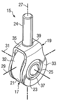
Figures 2A through 2B show oblique, side, and sectional views of one end
assembly 15. Rod end 17 is a spherical-bearing rod end, comprising an outer
bearing housing, or race, carried within a rigid body 21, a spherical ball 23
rotatably
carried within the outer housing and body 21, and a connector 24 extending
from
body 21 and configured for attachment to an object. Body 21 is shaped to allow
ball
23 to protrude from opposing sides of body 21. Ball 23 is shown with a
diametric
bore 25 extending through body 23, and bore 25 is configured for receiving a
fastener (an example is shown in Fig. 3) for attaching rod end 17 to an
object. Ball
23 is capable of rotation within body 21 about axes 27, 29, 31, allowing for
relative
rotation between body 21 and ball 23. A tapered portion 32 is formed on each
side
of body 21 that extends to connector 24 and may include a defined shoulder.
Clip 19
is configured to be assembled onto rod end 17 for substantially limiting
relative
rotation between body 21 and ball 23 to rotation primarily about axis 31.
Clip 19 is preferably formed from relatively soft, wearable plastic or a
similar
elastomeric material and comprises two spacer plates 33, a connector plate 35,
and
retaining means 37 for retaining clip 19 on rod end 17. Spacer plates 33 are
attached to connector plate 35 in a configuration that positions spacer plates
33
apart from each other and orients spacer plates 33 as generally parallel to
each
other. Connector plate 35 is shown with a curved profile, but connector plate
35 may
alternatively be formed =to have a profile of another shape. In the embodiment
of
Figures 2A through 2D, spacer plates extend from connector plate 35 for a
length
that is approximately equal to the length of body 21 of rod end 17. Holes 37
are
formed in spacer plates 33 to allow a fastener to pass through clip 19 and
ball 23. In
addition, an inner edge or surface of each hole 37 encircles the adjacent
protruding
portion of ball 23 and acts as retaining means for retaining clip 19 on rod
end 17.
Though shown as having a straight wall, hole 37 may have a.tapered or curved
wall,
such as a chamfer or bevel. Spacer plates 33 have a thickness t, as shown in
Figure
2C, that is preferably less than the distance ball 23 protrudes from each side
of body
3
CA 02676523 2009-07-24
WO 2008/100246 PCT/US2007/003597
21. Connector plate 35 also has a hole 39 for receiving connector 24 of rod
end 17,
and this configuration minimizes rotation of.cfip 19 relative to body 21.
To install clip 19 on rod end 17, clip 19 is oriented to align connector 24
with
hole 39 of connector plate 35. Connector 24 is inserted into hole 39, and rod
end 17
and clip 19 are oriented to allow body 21 to slide between spacer plates 33.
As the
protruding portions of ball 23 engage the outer ends of spacer plates 33,
plates 33
elastically deform away from each other, allowing ball 23 to pass between
plates 33.
Spacer plates 33 spring back toward each other as ball 23 enters holes 37,
retaining
clip 19 on rod end 17 and positioning spacer plates 33 generally adjacent body
21,
as shown in Figure 2C.
Figure 3 is an end view of an example installation of an end assembly 15 in a
clevis mount formed by clevis portions 41A, 41 B. A fastener is used to retain
end
assembly 15 within clevis portions 41A, 41B. In the exampfe shown, a bolt 43
comprises a head 45 and a shaft 47, which is inserted through clevis portion
41A,
through one spacer plate 33, through ball 23, through the other spacer plate
33, and
through clevis portion 41B. Shaft may, for example, have external threads (not
shown) for engaging threads of a nut 49 on the opposite side of the assembly
from
head 45. As can be seen in the figure, spacer plates 33 substantially fill the
space
between an inner face of each clevis portion 41A, 41B and the corresponding
side of
body 21, limiting rotation of body 21 about axes perpendicular to axis 31
while
allowing substantial rotation about axis 31. As mentioned above, thickness t
of
spacer plates 33 is preferably less than the distance ball 23 protrudes beyond
the
sides of body 21, and this allows clevis portions 41A, 41B to be tightened
against
ball 23 while providing clearance for rotation of spacer plates 33 primarily
about axis
31 relative to clevis portions 41A, 41 B.
Figure 4 is a side view of a portion of an aircraft with an installed spring-
damper assembly 11. A transmission 51 for a helicopter is mounted with a
transmission support 53 to an airframe 55. Transmission support 53 allows for
limited movement of transmission 51 relative to airframe 55, and spring-damper
assembly 11 is mounted between transmission 51 and airframe 55 for damping
this
motion. An end assembly 15, comprising a rod end 17 and a clip 19, is attached
to
4
CA 02676523 2009-07-24
WO 2008/100246 PCT/US2007/003597
each end of spring-damper 13, and each end assembly 15 is attached to one of a
pair of clevises 57, 59. Clevis 57 is attached to transmission 51, and spring-
damper
assembly 11 is attached to clevis 57 with a fastener 61 in a similar manner as
shown
in Figure 3. Likewise, clevis 59 is attached to transmission support 53 and
airframe
55, and spring-damper assembly 11 is attached to clevis 59 with fastener 63.
Clips
19 maintain body 21 of each rod end 17 in a generally vertical orientation,
preventing
each body 21 from contacting clevis 57, 59, which may cause binding or
undesirable
wear of clevises 57, 59 or bodies 21. In this manner clips 19 serve as
replaceable,
sacrificial elements.
Figures 5A through 5D, 6A through 6D, 7A through 7D, 8A through 8D, and
9A through 9D are views of alternate embodiments of self-retaining anti-
rotation
clips.
Figures 5A through 5D show oblique, side, and sectional views of an end
assembly 65, comprising a rod end 17, as described above, and a self-retaining
anti-
rotation clip 67. Clip 67 is configured to be assembled onto rod end 17 for
substantially limiting relative rotation between body 21 and ball 23 to
rotation
primarily about axis 31. Clip 67 is generally C-shaped and preferably formed
from
relatively soft, wearable plastic or a similar elastomeric material. Clip 67
comprises
two spacer plates 69, a connector plate 71, and retaining means 73 for
retaining clip
67 on rod end 17. Spacer plates 69 are attached to connector plate 71 in a
configuration that positions spacer plates 69 apart from each other and
orients
spacer plates 69 as generally parallel to each other. In the embodiment of
Figures
5A through 5D, spacer plates extend from connector plate 71 for only a portion
of the
length of body 21 of rod end 17. An inner edge 75 is formed on spacer plates
69,
the inner edge 75 partially surrounding the adjacent protruding portion of
ball 23.
Spacer plates 33 have a thickness t, as shown in Figure 5C, that is preferably
less
than the distance ball 23 protrudes from each side of body 21. A lip 73 is
formed on
each end of connector plate 71, and each lip 73 engages tapered portion 32 to
retain
clip 67 on rod end 17. As shown, lips 73 engage a shoulder of tapered. portion
32,
though a shoulder is not required. The shape of connector plate 71 cooperates
with
lips 73 to minimize rotation of clip 67 relative to body 21.
5
CA 02676523 2009-07-24
WO 2008/100246 PCT/US2007/003597
To install clip 67 on rod end 17, clip 67 is oriented to allow body 21 to
slide
between spacer plates 69. As lips 73 engage body 21,. lips 73 elastically
deform
away from each other, allowing body 21 to pass between lips 73. Lips 73 spring
back toward each other as the widest portion of body 21 passes lips 73, as
shown in
Figure 5D, retaining clip 67 on rod end 17 and positioning spacer plates 69
generally
adjacent body 21, as shown in Figure 5C.
Figures 6A through 6D show oblique, side, and sectional views of an end
assembly 77, comprising a rod end 17, as described above, and a self-retaining
anti-
rotation clip 79. Clip 79 is configured to be assembled onto rod end 17 for
substantially limiting relative rotation between body 21 and ball 23 to
rotation
primarily about axis 31. Clip 79 is generally C-shaped and preferably formed
from
relatively soft, wearable plastic or a similar elastomeric material. Clip.79
comprises
two spacer plates 81, a connector plate 83, and retaining means 85 for
retaining clip
79 on rod end 17. Spacer plates 81 are attached to connector plate 83 in a
configuration that positions spacer plates 81 apart from each other and
orients
spacer plates 81 as generally parallel to each other. In the embodiment of
Figures
6A through 6D, spacer plates extend from connector plate 83 for only a portion
of the
length of body 21 of rod end 17. An inner edge 87 is formed on spacer plates
81,
the inner edge 87 partially surrounding the adjacent protruding portion of
ball 23.
Spacer plates 81 have a thickness t, as shown in Figure 6C, that is preferably
less
than the distance ball 23 protrudes from each side of body 21. To retain clip
79 on
rod end 17, a lip 85 is formed on an inner surface of each spacer plate 81
that
engages a curved inner surface 91, such as a staking groove, of body 21. As
shown, each lip 85 is formed as a curve to generally mimic the curvature of
inner
surface 91. The shape of connector plate 83 cooperates with lips 85 to
minimize
rotation of clip 79 relative to body 21.
To install clip 79 on rod end 17, clip 79 is oriented to allow body 21 to
slide
between spacer plates 81. As lips 85 engage body 21, spacer plates 81
elastically
deform away from each other, allowing body 21 to pass between lips 85.. Spacer
plates 81 spring back toward each other as lips 85 pass inner surface 91, as
shown
6
CA 02676523 2009-07-24
WO 2008/100246 PCT/US2007/003597
in Figure 6C, retaining clip 79 on rod end 17 and positioning spacer plates 81
generally adjacent body 21, also shown in Figure 6C.
Figures 7A through 7D show oblique, side, and sectional views of an end
assembly 93, comprising a rod end 17, as described above, and a self-retaining
anti-
rotation clip 95. Clip 95 is configured to be assembled onto rod end 17 for
substantially limiting relative rotation between body 21 and ball 23 to
rotation
primarily about axis 31. Clip 95 comprises two preferably identical pieces and
is
preferably formed from relatively soft, wearable plastic or a similar
elastomeric
material. In the embodiment shown, the two pieces of clip 95 are formed by
bisecting clip 95 with a plane normal to axis 31. Each piece of clip 95
comprises a
spacer plate 97,- half of connector plate 99, and retaining means 101 for
retaining clip
95 on rod end 17. Each spacer plate 97 is attached to the associated half of
connector plate 99 in a configuration that positions spacer plates 97 apart
from each
other and orients spacer plates 97 as generally parallel to each other. In the
embodiment of Figures 7A through 7D, the pieces of clip 95 assemble to form an
enclosure around rod end 17, and each piece has a hole 103 encircling the
associated protruding portion of ball 23. Spacer plates 97 have a thickness t,
as
shown in Figure 7C, that is preferably less than the distance ball 23
protrudes from
each side of body 21. To retain clip 95 on rod end 17, cooperating tab
fasteners 101
are formed on each piece of clip 95, each portion of tab fasteners 101 on one
piece
of clip 95 engaging a corresponding portion on the other piece of clip 95 to
retain the
pieces together. Connector plate 99 has a hole 105 for receiving connector 24
of rod
end 17, one half of hole 105 - being formed in each piece of clip 95. This
configuration minimizes rotation of clip 95 relative to body 21. To install
clip 95 on
rod end 17, each piece of clip 95 is oriented to align with the appropriate
features of
rod end 17 and the pieces are snapped together using tab fasteners 101. This
positions spacer plates 97 generally adjacent body 21, also shown in Figure
7C.
Figures 8A through 8D show oblique, side, and sectional views of an .end
assembly 107, comprising a rod end 17, as described above, and a self-
retaining
anti-rotation clip 109. Clip 109 is configured to be assembled onto rod end 17
for
substantially limiting relative rotation between body 21 and ball 23 to
rotation
7
CA 02676523 2009-07-24
WO 2008/100246 PCT/US2007/003597
primarily about axis 31. Clip 109 comprises two preferably identical pieces
and is
preferably formed from relatively soft, wearable plastic or a similar
elastomeric
material. In the embodiment shown, the two pieces of clip 109 are formed by
bisecting clip 109 with a plane that contains axis 31 and bisects body 21 of
rod end
17. Each piece of clip 109 comprises half of each spacer plate 111, half of
connector plate 113, and half of retaining means 115 for retaining clip 109 on
rod
end 17. Each half of spacer plate 111 is attached to the associated half of
connector
plate 113 in a configuration that positions spacer plates 111 apart from each
other
and orients spacer plates 111 as generally parallel to each other. In the
embodiment
of Figures 8A through 8D, the pieces of clip 109 assemble to form an enclosure
around rod end 17, and each piece has half of each of two holes 117 encircling
the
associated protruding portion of ball 23. Spacer plates 111 have a thickness
t, as
shown in Figure 8C, that is preferably less than the distance ball 23
protrudes from
each side of body 21. To retain pieces of clip 109 to each other and retain
clip 109
on rod end 17, cooperating tab fasteners 115 are formed on each piece of clip
109,
each portion of tab fasteners 115 on one piece of clip 109 engaging a
corresponding
portion on the other piece of clip 109 to retain the pieces together.
Connector plate
113 has a hole 119 for receiving connector 24 of rod end 17, one half of hole
119
being formed in each piece of clip 109. This configuration minimizes rotation
of clip
109 relative to body 21. To install clip 109 on rod end 17, each piece of clip
109 is
oriented to align with the appropriate features of rod end 17 and the pieces
are
snapped together using tab fasteners 115. This positions spacer plates 111
generally adjacent body 21, also shown in Figure 8C.
Figures 9A through 9D show oblique, side, and sectional views of an end
assembly 121, comprising a rod end 17, as described above, and a self-
retaining
anti-rotation clip 123. Clip 123 is configured to be assembled onto rod end 17
for
substantially limiting relative rotation between body 21 and ball 23 to
rotation
primarily about axis 31. Clip 123 comprises two preferably identical sides and
is
preferably formed from relatively soft, wearable plastic or a similar
elastomeric
material. In the embodiment shown, the two sides of clip 123 are formed by
bisecting clip 123 with a plane that contains axis 31 and bisects body 21 of
rod end
17. Each side of clip 123 comprises half of each spacer plate 125, half of
connector
8
CA 02676523 2009-07-24
WO 2008/100246 PCT/US2007/003597
plate 127, and half of retaining means 129 for retaining clip 123 on rod end
17. Each
half of spacer plate 125 is attached to the associated half of connector plate
127 in a
configuration that positions spacer plates 125 apart from each other and
orients
spacer plates 125 as generally parallel to each other. In the embodiment of
Figures
9A through 9D, the sides of clip 123 are connected to each other with an
integral
hinge 131, and the sides close in a"clamshelP' manner to form an enclosure
around
rod end 17. Each side has half of each of two holes 133 encircling the
associated
protruding portion of ball 23. Spacer plates 125 have a thickness t, as shown
in
Figure 9C, that is preferably less than the distance ball 23 protrudes from
each side
of body 21. To retain sides of clip 123 to each other and retain clip 123 on
rod end
17, cooperating tab fasteners 129 are formed on each side of clip 123, each
portion
of tab fasteners 129 on one side of clip 123 engaging a corresponding portion
on the
other side of clip= 123 to retain the sides together. Connector plate 127 has
a hole
135 for receiving connector 24 of rod end 17, one half of hole 135 being
formed in
each side of clip 123. This configuration minimizes rotation of clip 123
relative to
body 21. To install clip 123 on rod end 17, clip 123 is oriented to align the
sides with
the appropriate features of rod end 17 and the sides are* hinged toward each
other
and snapped together using tab fasteners 129. This positions spacer plates 125
generally adjacent body 21, also shown in Figure 9C. Though shown with hinge
131
being formed on an end of clip 123, hinge 131 may be formed in another
location or
orientation on clip 123.
It should be noted that each of the features shown in the embodiments
described above may be used in combination with features shown in another
embodiment. For example, a lip, configured like lip 85 of Figures 6A through
6D,
may be used on any of the embodiments to assist in locating the clip on the
rod end.
It should also be noted that clips 95, 109, and 123 are shown and described as
preferably being bisected into identical sides or pieces, though it is not
required that
the sides or pieces be identical. Clips 95, 109, 123 may be formed to have non-
identical sides or pieces, wherein unequal portions of connector plates,
spacer
plates, or other features, such as holes, may be formed on the sides or
pieces.
9
CA 02676523 2009-07-24
WO 2008/100246 PCT/US2007/003597
The self-retaining anti-rotation clip provides for several advantages,
including:
(1) the clip remains assembled on a spherical bearing or rod end when the
bearing
or rod end is detached from another object; (2) the clip has low weight and
cost
through the use of plastic or elastomeric material; (3) the clip is easy to
install and
uninstall; (4).the clip requires no modification to the spherical. bearing,
rod end, or
clevis portions; and (5) the clip is sacrificial. When sufficient clearance
around rod
end 17 exists, clips 67, 79, 109, and 123 have the additional advantage of
being
installable or replaceable without the need to disassemble rod end 17 from the
associated clevis.
While this invention has been described with reference to illustrative
embodiments, this description is not intended to be construed in a limiting
sense.
Various modifications and combirtations of the illustrative embodiments, as
well -as
other embodiments of the invention, will be apparent to persons skilled in the
art
upon reference to the description.