Note: Descriptions are shown in the official language in which they were submitted.
CA 02676537 2009-07-24
WO 2007/087634
PCT/US2007/061164
Valve Assembly for Paintball Guns and the Like, and Improved Guns
Incorporating the
Assembly
BACKGROUND OF THE INVENTION
1. FIELD OF THE INVENTION
This invention pertains generally to the field of mechanical guns and
projectors, and more
particularly to fluid pressure propulsion, with control for discharge of fluid
pressure provided by
a valve. In a preferred embodiment, the present invention is manifested in a
single-axis bolt and
valve assembly used within a paintball marker.
2. DESCRIPTION OF THE RELATED ART
0
Fluid pressure propulsion has been used in combination with various types of
guns and
projectors for many years. As an alternative to gun powder and other explosive
substances,
various pump guns existed which allowed an operator to pump air into a chamber
until sufficient
fluid was compressed to attain the necessary pressure to reasonably fire a
projectile. Many BB
and pellet guns were sold for many years that utilized this technology. These
guns, while fully
L 5
functional and capable of firing projectiles at great speeds, suffered from
many significant
drawbacks. Foremost among these was the inability to keep the gun in a ready-
to-fire state,
commonly due to slow leakage through the pumping mechanisms, and the delay
time between
firing successive shots, necessitated by the need to pump another charge of
air into the pressure
chamber after each shot. In addition, having been designed to resemble the gun
powder versions,
! 0
they were often rather large and heavy. While weight reduces recoil in gun
powder versions, it
is of lesser importance in the less powerful pump guns.
1
CA 02676537 2009-07-24
WO 2007/087634
PCT/US2007/061164
As an alternative to and improvement over the pump-pressure guns, various gas
and
liquified gas cylinders were provided to deliver a steady source of fluid
pressure to the gun.
Exemplary of these were the CO2 cartridges which were small and lightweight,
but which
provided a very limited number of successive firings before requiring
replacement. To fire these
guns, various mechanical triggering devices were used to control the actuation
of a valve.
Common valves required a substantial amount of time to activate and reset,
which in view of the
relatively small number of shots available was not normally considered a
limitation for these
guns.
A number of years ago, a new gun was developed which would fire small capsules
or
balls of paint that were frangible, and so would break relatively easily upon
impact. By filling
the frangible exterior shell with liquid paint, it was possible to visually
determine whether a
participant had been "hit". Consequently, the guns are commonly referred to as
markers, since
rather than inflicting harm or death, a paintball gun marks the point of
impact. The early markers
made it possible to conduct relatively close-range training drills for
military and civilian training,
without the need for other types of complex, expensive and unreliable training
weapons or the
fear of serious harm that would be associated with more traditional guns.
Many developments have occurred over the years that have evolved the early
paintball
guns into the more modern counterparts. These developments have occurred in
all aspects,
affecting not only the technology of firing and propulsion, but also in areas
separate and distinct
from the guns, such as safety and in the formal organization of teams and
competitions. In a
comparatively few recent years, the development has progressed and evolved
into both a science
and industry of its own. As a sport, paintball has been identified as the
third largest participant
sport in the United States with millions of participants, has substantial
numbers of participants
and competitions the world over, and continues to grow in popularity both in
numbers of
2
CA 02676537 2009-07-24
WO 2007/087634
PCT/US2007/061164
participants and in spectators.
One area of development which has and continues to be very challenging to gun
designers
is the firing rate of a gun. To be most effective, a modern paintball gun will
preferably be
capable of firing paint balls at rates not measured in balls per second, but
instead in the tens of
balls per second. More rapid firing rates permit the balls to be distributed
through lesser angles
of an arc, in the event the gun is being moved while being fired. Since
movement and motion
are inseparable from paintball, the higher firing rate translates into a
greater likelihood of
marking an opponent. This can be readily contrasted with the pneumatic guns
outside of the
paintball industry, where firing rates are more commonly measured in seconds
per shot or in only
a few shots per second.
Another demanding area of development is the size and weight of the gun. While
size
and weight are often interrelated in most products since a larger product of
otherwise identical
construction will weigh more, in the case of a paintball gun the size and
weight bring about
different benefits and so are somewhat independent. With regard to weight, the
gun must be held
and moved about. At times, such as when surprised by an opponent, the gun will
most desirably
redirected in as little time as possible. Lower weight guns can be moved about
more quickly, and
may further be aimed in less time. With regard to size, the gun will sometimes
be held out
beyond the shelter of a barrier, exposing only the gun and not the person. The
smaller a gun, the
more difficult it will be to be marked by an opponent.
Additional areas that have required much consideration and development have
included
the reliability of successfully firing the gun, and the ease of cleaning out
the gun when a paint
ball is broken within the gun. When a paint ball breaks within the gun, a way
must be provided
to remove the components since paint will be smeared or splashed about inside
the gun, and
without cleaning, will increasingly interfere with proper operation. The more
readily the
3
CA 02676537 2009-07-24
WO 2007/087634
PCT/US2007/061164
components along the path of the ball are removed, the easier and quicker it
will be for a
participant to recover from a broken ball. Nevertheless, the precision of
components and
operation must still be maintained, or there will be many more balls breaking.
SUMMARY OF THE INVENTION
Exemplary embodiments of the present invention solve inadequacies of the prior
art by
providing a single cartridge that is inserted into and removed from a gun
body. The cartridge
includes a low pressure ram capable of being driven in opposite reciprocal
directions, a
volumizer for storing a charge of high pressure gas sufficient to adequately
propel a paint ball,
a high pressure valve driven by movement of the low pressure ram for releasing
the charge
rapidly, and a bolt carried upon the low pressure ram for moving a paint ball
into firing position
just prior to the high pressure discharge. All of the aforementioned
components of the cartridge
are carried upon a single axis, through which the low pressure ram passes.
Means are provided
to both align and couple the various components together to ensure proper
operation at high
firing rates.
As described in a first manifestation, the invention is a valve assembly for
paintball guns
and the like. The valve assembly has an end cap, a low-pressure ram chamber
having at least two
ports spaced distally from each other and each operative to allow gas to pass
through, and a ram
having a ram head and 0-ring dividing the low-pressure ram chamber into a
first and a second
low-pressure enclosure. The first low-pressure enclosure is in communication
with a first one
of the at least two ports and the second low-pressure enclosure is in
communication with a
second one of the at least two ports, the first port isolated from the second
port. A bolt is coupled
for relative movement with the ram and has at least one hole penetrating
longitudinally through
the bolt, and a plurality of seals cooperative with a gun barrel and feed neck
to seal the feed neck
4
CA 02676537 2013-10-11
from a blast of high pressure gas during gun firing. A volumizer has a high
pressure
inlet to a volumizer enclosure, and at least one flow port coupling an
exterior of the
volumizer to the at least one hole penetrating through the bolt. A high
pressure valve
controls flow from the volumizer enclosure to flow port. Each of the end cap.
low-
pressure ram chamber, ram, bolt, volumizer and valve are constrained within
the
valve assembly such that the valve assembly remains a single integrated unit
not only
during normal operation but also during removal from and insertion into a gun
body.
In a second manifestation, the invention is a paintball gun. The gun has a
feed
neck for receiving paint balls into a breech from an external source. A barrel
coupler
couples the gun to a gun barrel. A source of high pressure gas is coupled to
the gun
for distribution within the gun. A human interface is provided for manual
initiation
gun firing. A gun body has a bore therein in line with the barrel coupler. A
valve
assembly is held within the bore in the gun body, and has an end cap, ram, low-
pressure ram chamber, volumizer, valve, and bolt, the ram extending from
adjacent
the end cap to the bolt and coupled with the valve to activate the valve when
the ram
is driven away from the end cap.
In a third manifestation, the invention is a method of firing a projectile
from a
hand-held gun having a gun barrel. According to the method, low pressure gas
is
delivered into an enclosed chamber of variable volume. A ram defining the
variable
volume is driven responsive to the low pressure gas delivery. A paint ball is
advanced
from a breech into a firing position within the hand-held gun body responsive
to the
driving step. A high pressure valve is activated responsive to the driving
step and
subsequent to the advancing step. High-pressure gas which has been stored
within an
enclosure is released in a rapid burst responsive to the activating step, and
is then
conducted to the paint ball and down the gun barrel.
Accordingly, in one aspect the present invention resides in a valve assembly
for paintball guns and the like, comprising an end cap; a low-pressure ram
chamber
having at least two ports spaced distally from each other and each operative
to allow
gas to pass through; a ram having a ram head and a seal dividing said low-
pressure
ram chamber into a first low-pressure enclosure and a second low-pressure
enclosure,
said first low-pressure enclosure in communication with a first one of said at
least two
ports and said second low-pressure enclosure in communication with a second
one of
CA 02676537 2013-10-11
said at least two ports, said first port isolated from said second port; a
bolt coupled for
relative movement with said ram and having at least one hole penetrating
longitudinally through said bolt, and a plurality of seals cooperative with a
gun barrel
and a feed neck to seal said feed neck from a blast of high pressure gas
during gun
firing; a volumizer having a high pressure inlet to a volumizer enclosure, at
least
one flow port coupling an exterior of said volumizer to said at least one hole
penetrating through said bolt; a high pressure valve controlling flow from
said
volumizer enclosure to said flow port; each of said end cap, said low-pressure
ram
chamber, said ram, said bolt, said volumizer and said valve constrained within
said
valve assembly such that said valve assembly remains a single integrated unit
not only
during normal operation but also during removal from and insertion into a gun
body,
wherein said ram further comprises a longitudinally extensive body of a first
diameter throughout at least a majority of said longitudinal extension, said
longitudinally extensive body passing through said low pressure ram chamber
and
said valve.
In another aspect the present invention resides in a paintball gun, comprising
a feed neck for receiving paint balls into a breech from an external source; a
barrel
coupler for coupling to a gun barrel; a source of high pressure gas coupled
for
distribution; a human interface for manual initiation gun firing; a gun body
having a
bore therein in line with said barrel coupler; a valve assembly held within a
bore in
said gun body having an end cap, a ram, a low-pressure ram chamber, a
volumizer, a
valve, and a bolt, said ram extending from adjacent said end cap to said bolt
and
coupled with said valve to activate said valve when driven away from said end
cap,
said ram passing inside of and coaxially through the center of said valve.
In a further aspect the present invention resides in a method of firing a
projectile from a hand-held gun having a gun barrel, comprising the steps of:
delivering low pressure gas into an enclosed chamber of variable volume;
driving a
ram defining said variable volume responsive to said low pressure gas
delivery;
advancing a paint ball from a breech into a firing position within said hand-
held gun
body responsive to said driving step; activating a high pressure valve
responsive to
said driving step and subsequent to said advancing step; releasing high-
pressure gas
which has been stored within an enclosure in a rapid burst responsive to said
5a
CA 02676537 2013-10-11
activating step; and conducting said released high pressure gas to said paint
ball and
down said gun barrel, wherein said step of driving further comprises moving
said ram
coaxially with and internal to said high pressure valve and coaxial with said
gun
barrel.
5b
CA 02676537 2009-07-24
WO 2007/087634
PCT/US2007/061164
OBJECTS OF THE INVENTION
A first object of the invention is to provide a paintball gun which will
preferably be
capable of firing paint balls at rates measured in the tens of balls per
second. A second object
of the invention is to lower the size and weight of the gun relative to the
prior art. Another object
of the present invention is to improve the reliability of successfully firing
the gun, and also
simultaneously ease gun cleaning when a paint ball is broken within the gun.
BRIEF DESCRIPTION OF THE DRAWINGS
The foregoing and other objects, advantages, and novel features of the present
invention
can be understood and appreciated by reference to the following detailed
description of the
invention, taken in conjunction with the accompanying drawings, in which:
FIG. 1 illustrates a paintball gun incorporating the present invention from
side plan view
with the barrel, magazine and gas cartridge removed.
FIG. 2 illustrates a preferred embodiment valve assembly designed in accord
with the
teachings of the present invention and operative with the preferred embodiment
gun of Fig. 1,
from a side plan view and in a stationary but ready-to-be-fired position.
FIG. 3 illustrates the preferred embodiment valve assembly of Figure 2 from a
projected
plan view and in a during-firing position.
FIG. 4 illustrates the preferred embodiment valve assembly of Fig. 2 from a
sectional
view taken along section line 4' of Fig. 3, which corresponds to a plane
parallel to the page in Fig.
2.
FIG. 5 illustrates the preferred embodiment valve assembly of Fig. 4 in a
position
immediately prior to high pressure discharge.
FIG. 6 illustrates the preferred embodiment valve assembly of Fig. 4 in a
position during
6
CA 02676537 2009-07-24
WO 2007/087634
PCT/US2007/061164
firing, at the time of high pressure discharge, and illustrating the flow of
high pressure gas
through the assembly.
DESCRIPTION OF THE PREFERRED EMBODIMENT
A paintball gun 100, also referred to as a paintball marker, is shown by an
external side
plan view in figure 1. As illustrated therein, a feed neck 110 is provided for
introducing paint
balls into gun 100. The source of paint balls is not consequential to the
present invention, but
may be a magazine such as a hopper, a powered ball feeder, or other device
known in the art to
provide a high speed, high volume source of paint balls. The paint balls will
pass from feed neck
110 into gun body 120, where they will rest in the breech. From there, the
balls will be moved
forward, and then fired, or violently expelled by a high-pressure blast,
through barrel coupler 124
and out a gun barrel as is known in the art. A high pressure gas canister is
coupled, either
directly or indirectly, through coupler 130. High pressure gas will pass from
coupler 130 through
hose 135 and into pressure regulator 140 for distribution into gun body 120. A
handle 150 and
trigger 160 provide the human interface with gun 100 for holding the gun and
initiating firing,
and handle 150 will often house a battery and electronic controls that may be
used with modem
paintball guns.
Adjacent the end 122 of gun body 120, distal to barrel coupler 124, is the
very end of
valve assembly 200. Valve assembly 200 is held within a bore in gun body 120
in line with a gun
barrel longitudinal axis. This valve assembly 200 is designed to slide into
and out from the bore
as a single unit, which permits rapid removal for cleaning and repairs.
Furthermore, since the
bore within gun body 120 is along a single axis and in line with the barrel,
both inspection and
cleaning are simplified.
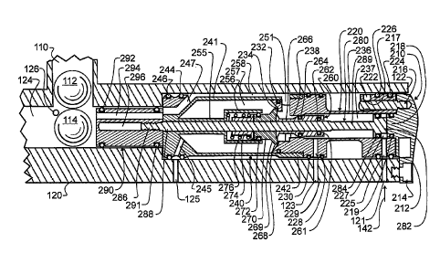
The preferred embodiment valve assembly 200 is illustrated in Figure 2 removed
from
7
CA 02676537 2009-07-24
WO 2007/087634
PCT/US2007/061164
gun body 120, but oriented as it would be in Figure 1. Consequently, in Figure
1 the only
component of valve assembly 200 which is visible is a portion of end cap 210,
including locking
and alignment wing 212. Valve assembly 200 has several primary components in
addition to end
cap 210. These include the low-pressure ram chamber 220, volumizer 240, and
bolt 290. Each
of these components is constrained within valve assembly 200, such that valve
assembly 200
remains a single integrated unit not only during normal operation but also
during removal from
and insertion into gun body 120.
In operation, at the start of a firing sequence low pressure gas is delivered
into port 225,
and simultaneously exhausted from port 229. The gas will preferably be
introduced through
small ports or openings within gun body 120 or other suitable tube concentric
about valve
assembly 200. The ports that deliver the pressurized gas do not have to align
with ports 225 and
229, but instead must fall between the adjacent 0-ring seals. 0-rings 224 and
226 will then trap
and constrain the flow of pressurized gas with respect to port 225 and 0-rings
228, 230 trap and
constrain the flow of pressurized gas with respect to port 229, such that the
gas can only flow into
or from ports 225 and 229 and not be dispersed or intermingled.
Flow into port 225 and exhaust from port 229, the control of which is
preferably but not
mandatorily provided by at least one electrically controlled valve, causes a
low pressure ram (280
visible in Figures 4 - 6) to travel, and ultimately activate a high pressure
valve (poppet valve 260,
visible in Figures 4 - 6). Tied directly to the low pressure rani 280 is bolt
290, which means bolt
290 will advance a paint ba11114 from the breech into a firing position within
gun body 120.
Once the low pressure ram 280 has traveled sufficiently far to set the
position of bolt 290, a small
additional motion will trigger the actuation of high pressure valve 260 within
volumizer 240.
This in turn will release high-pressure gas which has been stored within
volumizer 240 in a rapid
burst, from where it will pass ultimately through bolt 290 and down the
barrel. High pressure
8
CA 02676537 2009-07-24
WO 2007/087634
PCT/US2007/061164
gas is admitted into volumizer 240 through one or more ports such as 243, 245.
Isolating the
ports243 and 245 are 0-rings 244 and 246. The 0-rings 291,292 found on bolt
290 serve to seal
feed neck 110 from the blast of high pressure gas during firing, so that balls
such as ball 112
within feed neck 110 are not blown away from gun body 120 or out of feed neck
110. The
remaining features numbered within Figure 2 pertain to volumizer 240, the
operation and
construction which will be better explained herein below with reference to
Figure 4.
Figure 3 illustrates valve assembly 200 from a projected view. This projected
view, the
side plan view Figure 2, and the sectional views of Figures 4-6 will be
described together, with
only limited reference to any specific figures. As already described with
regard to Figure 2, an
isolated low-pressure system drives a low-pressure ram 280, which in turn
moves the sliding
shaft and activates poppet valve 260. More specifically, end cap 210 has a
small protrusion 218
which, in combination with 0-ring 219, low pressure valve body 236, ram head
282 and 0-ring
284, forms a variable volume low pressure enclosure 227. As low-pressure gas
is introduced into
enclosure 227 through ports 121 and 225, as illustrated by flow an-ow 142 in
Figure 4, the
volume of enclosure 227 will increase by driving ram head 282 farther from
protrusion 218 in
end cap 210. Ram 280 is directly coupled to bolt 290, thereby moving bolt 290
towards the
position illustrated in Figure 5. While not illustrated and the exact
apparatus and method which
are not consequential to the present invention, those skilled in the art will
understand and
recognize the myriad ways of coupling the output of a low-pressure regulator
to port 121, such
as through an electric valve to a hose coupled into port 121. The coupling
which connects the
hose into port 121 will commonly take the form of a small tube threaded at one
end for screwing
into port 121, and barbed at the other to permit a hose to be slid thereon and
not easily removed
therefrom, though the particular means of coupling of pressurized gas is not
critical to the
performance of the present invention so long as the gas is in fact provided in
a reliable manner.
9
CA 02676537 2009-07-24
WO 2007/087634
PCT/US2007/061164
While the volume of enclosure 227 is increasing, the volume of enclosure 237
is
decreasing. In order to permit enclosure 237 to decrease in volume without
increasing in
pressure, gas retained therein is most preferably vented through an
electrically controlled valve
or the like to atmosphere. This arrangement has only a few limiting factors to
how quickly ram
280 may be moved. A first limiting factor is how quickly the low pressure gas
can be introduced
into enclosure 227. This is limited or in some instances controlled by the
pressure of the low
pressure gas at the ports 121, 225, and the cross-sectional area and any flow
restrictions in ports
121 and 225 and any other consequential flow restrictions between these ports
and the source of
low pressure gas. The preferred embodiment has no consequential flow
restrictions between the
0 ports and low pressure source, since the only items between the ports and
gas tank are pressure
regulators, which inherently only maintain pressure and thereby provide no
consequential flow
restriction, and the electric valve and hoses. The valve and hoses should be
large enough to
permit operation of ram 280 at any rate desired.
At any time, reversal of ram travel is achieved by applying gas from the low
pressure
5 source through ports 123, 229, which pass through and into the interior
of low-pressure housing
220 in enclosure 237, on the side of ram 280 distal to end cap 210. At the
same time, gas within
enclosure 227 will desirably be vented to atmosphere. This causes ram 280 to
move towards end
cap 210, in turn resetting ram 280 and bolt 290 for the next firing sequence.
Consequently, ram
280 travels in a linear path, simply reciprocating in direction controlled by
the relative pressures
0 between enclosures 227, 237.
The high pressure gas flow is illustrated by arrows in Figure 6, though the
reference
numerals described herein will be found on Figures 2 - 4. Volumizer 240, best
visible in figure
3, includes three distinct sets of holes or ports through which the high
pressure gas will pass.
One set are the high pressure inlets 243, 245 to the volumizer core. While two
holes are visible
CA 02676537 2009-07-24
WO 2007/087634
PCT/US2007/061164
in the figures, it will be understood that in the preferred embodiment, three
are used and that any
suitable number may be used. These holes are placed between each of the flow
ports 247 - 249.
The exact number or size of high pressure inlets and flow ports are not
critical to the operation
of the invention, so long as there is an appropriate flow restriction induced
by each for the
appropriate function. These high pressure inlets 243, 245 extend through the
volumizer body
from exterior to interior, and permit high pressure gas to pass from the high
pressure regulator
into volumizer 240 enclosure 257. Like end cap 210 and low-pressure housing
220, volumizer
240 does not move with respect to gun body 120. Consequently, two 0-rings
244,246 are used
to capture and isolate the high-pressure inlet to volumizer 240. As
aforementioned, angularly
displaced from each high-pressure inlet 243, 245, and thereby completely
isolated therefrom, are
a plurality of flow ports 247 - 249, best illustrated in Figure 3. These flow
ports 247 - 249 couple
a flow path 258, labeled in Figure 4 and formed between volumizer 240 wall 241
and gun body
120, through volumizer 240 wall to bolt 290. These flow ports 247 - 249 do not
pass into the
interior of the volumizer body, and instead only serve to port the high-
pressure gas from the
volumizer exterior flow path 258 to bolt 290.
In operation, volumizer 240 is filled in enclosure 257 with high-pressure gas
passing from
the high-pressure regulator through port 125 in gun body 120 to ports 243,245
in volumizer 240,
and from these ports into the volumizer enclosure 257. The filling of
enclosure 257 may occur
at any time, so long as volumizer enclosure 257 is fully pressurized prior to
being discharged.
Said another way, the size of ports 125, 243, 245, the pressure of the high-
pressure source, and
any other flow restrictions will control the amount of time needed to fully
charge enclosure 257.
Consequently, in the preferred embodiment an electrically controlled valve is
used to initiate the
charge of volumizer enclosure 257 sufficiently in advance of firing to reach
full pressure. This
may in one embodiment occur at the same time low-pressure gas is being
introduced into port
11
CA 02676537 2009-07-24
WO 2007/087634
PCT/US2007/061164
225, though the timing may be different therefrom as desired or required.
Poppet valve 260 is initially closed, preventing escape of gas from volumizer
enclosure
257. Consequently, the exterior of volumizer 240, defined by flow path 258, is
at atmospheric
pressure, being coupled from the barrel through bolt 290, and then through
flow ports 247- 249
formed in the volumizer wall that connect from bolt 290 to the volumizer wall
241 exterior.
However, when poppet valve 260 is opened, high pressure gas accumulated within
volumizer
enclosure 257 will be discharged through poppet outlet 251 into the space
between the volumizer
and gun body 120 defined by flow path 258, which forms a passageway to the
flow ports 247 -
249. As already noted, these ports 247 - 249 pass from the volumizer exterior
of wall 241 to
immediately adjacent bolt 290, all the while isolated within the wall of the
volumizer from
volumizer enclosure 257. Then the gas passes through holes 294 in the bolt
into the firing
chamber. One of these holes is visible in Figures 4- 6 by cross-section, but
the full plurality of
holes 294 used in the preferred embodiment are best visible in Figure 3.
The movement of ram 280 is used to drive bolt 290 forward past ball-retaining
detent 126
and position paint ball 114 within the firing chamber, and simultaneously
therewith, when bolt
290 is in proper position, to activate poppet valve 260. As aforementioned,
the 0-rings 291,292
at either end of and circumscribing bolt 290 isolates the firing chamber from
paint ball feed neck
110, thereby preventing any passage of high pressure gas into the paint ball
inlet passage.
Consequently, all components are operated upon a single longitudinal axis, in
line with the gun
barrel, through a single sliding ram 280.
In order to achieve this single-axis operation, poppet valve 260 has been
located in the
middle of valve assembly 200, between the low-pressure housing 220 and bolt
290. Such
placement is in stark contrast to the prior art, where the poppet valve is
placed at an end of the
shaft and gun, and on a different axis from the barrel. The single-axis
operation of the present
12
CA 02676537 2009-07-24
WO 2007/087634
PCT/US2007/061164
invention is achieved by novel porting of the high pressure gas first into
volumizer interior 257,
and then around volumizer wall 241, using wall 241 to isolate flow ports 247 -
249 from the
interior 257 of volumizer 240.
Poppet valve 260 encompasses ram 280. At the end of valve 260 adjacent
enclosure 237,
an internal 0-ring 262 seals ram 280 and valve hammer surface 261, so that low-
pressure or
atmospheric pressure gas within enclosure 237 is isolated from either
atmospheric or high-
pressure gas found at the end of ram 280 adjacent to bolt 290. External 0-ring
264 similarly
isolates enclosure 237 from either atmospheric or high-pressure gas found
within poppet outlet
251. Distal to valve hammer surface 261 is a spring 276 nested within
volumizer cup 256. Cup
256 in the preferred embodiment is supported upon a cup support shaft 255
extending from the
end of volumizer 240 adjacent to bolt 290, though the method of supporting cup
256 is not
critical, and other suitable constructions or geometries may be used.
In order to best accelerate the travel of ram 280, friction will desirably be
kept at a
minimum. In order to reduce friction, a small amount of initial movement of
rain 280 away from
L 5 end cap 210 releases the seal between 0-ring 260 and ram 280. This is
enabled by the necked
down region 289 in ram 280, which with very little motion is adjacent to 0-
ring 260 and so not
frictionally engaged therewith.
Spring 276 generates separation forces between cup 256 and spring sleeve 274,
which in
turn presses against valve body 268. Valve body 268 most preferably has a
small flare 269
0 extending from cylindrical core 270. Too large a flare will cause the
surface area to be too great,
and will consequently require the low pressure side undesirably be much closer
in pressure to the
high pressure source in order for the low-pressure ram 280 to generate more
force than is being
produced by the high pressure against valve body 268. In order to prevent
leakage between valve
body 268 and supporting cup 256, an 0-ring seal 272 is provided.
13
CA 02676537 2009-07-24
WO 2007/087634
PCT/US2007/061164
When ram 280 is driven away from end cap 210, it slides relatively
unrestricted through
valve 260, only contacting therewith at 0-ring 262, and even then only for a
very short distance
of travel. Alignment of ram 280 while traveling is maintained through 0-ring
284 engaging with
low-pressure valve body 236 at the low-pressure end adjacent end cap 210, and
through 0-ring
291 engaging with gun body 120 adjacent in feed 110. Eventually, as
illustrated in Figure 5, top-
hat shaped ram head 282 will be traveling at a relatively high rate of speed
and will engage with
valve hammer surface 261. This position illustrated in Figure 5 is arrived at
just prior to
activation of valve 260.
Any further motion, which is not only assisted by the low-pressure generated
force but
also by the momentum of ram 280, will lead to movement of valve hammer surface
261 also
away from end cap 210. The movement of valve hammer surface 261 will lead to
translation of
valve body 268 and spring sleeve 274 as well, in turn compressing sleeve 274.
Most preferably,
shoulder 238 against which 0-ring 264 seats is sufficiently long along the
axis of motion of ram
280 to ensure that the seal there between is maintained through the full
movement of valve body
L5 26.
As valve body 268 is moved away from valve seat 234, pressure is released from
volurnizer enclosure 257 into poppet outlet 251. This release of pressure
removes the force
which had existed on valve body 268 which was opposing movement of ram 280,
leading to a
sudden acceleration of both ram 280 and valve body 268. In this way, there is
ensured a rapid
a 0 discharge of the pressurized gas within volumizer enclosure 257. As the
gas is discharged, it is
passed through flow controlling surface 266, which is preferably shaped for
more smooth and
laminar flow of air to maintain the efficiency of flow and improve the paint
ball velocity at a
given operating pressure.
This high-pressure gas discharge position is illustrated in Figure 6, and the
flow of the
14
CA 02676537 2009-07-24
WO 2007/087634
PCT/US2007/061164
high pressure gas is illustrated by the inlet stream 144 and the subsequent
flow path already
detailed herein above. As also shown in Figure 6, the low-pressure inlet flow
142 is still open,
maintaining the position of ram 280 against the force of spring 276. While
spring 276 is not
strictly required, the inclusion of this spring adds a certain amount of "pop"
to the return motion
of ram 280 after firing, due to the release of stored mechanical energy in the
compression of
spring 276. This "pop" or quick acceleration can occur more quickly than the
initial building of
gas pressure within enclosure 237, which pressure will preferably be timed to
occur at such a
time as to induce motion of both ram 280 and valve 260 back towards end cap
210, starting after
the proper discharge of high pressure gas from within enclosure 257.
In accord with the teachings of the present invention, the preferred valve
assembly 200
is manufactured as a number of discrete parts that are assembled into a
single, modular
component. The entire valve assembly 200 is held in place within gun body 120
by an anchoring
screw passing through hole 214 in wing 212 into gun body 120. End cap 210 is
rigidly coupled
and aligned with low-pressure ram chamber 220 via one or more alignment pins
216 which are
rigidly affixed to end cap 210 and which pass through an alignment hole formed
in low-pressure
ram chamber 220, as is visible in Figures 3 - 6. To securely fasten end cap
210 to low-pressure
ram chamber 220, each alignment pin 216 is provided with a neck 217 into which
a set screw 222
will engage. By proper shaping of neck 217, tightening of set screw 222 will
draw end cap 210
tight against low-pressure ram chamber 220. Low-pressure ram chamber 220
couples with
volumizer 240 through an external set of threads that thread into internally
threaded volumizer
flange 242. Finally, bolt 290 is threaded onto the threaded end 286 of ram
280.
A combination of as many relatively large holes 294 as possible and an
extended bore 296
reduce the material and consequently the mass of bolt 290. Similarly, the
diameter of ram 280
and total size of ram head 282 are kept to a minimum, likewise reducing the
total mass. These
CA 02676537 2009-07-24
WO 2007/087634
PCT/US2007/061164
reductions in mass reduce the time required to move ram 280 and bolt 290 in
the reciprocal
manner required for the operation of gun 100, thereby increasing the maximum
attainable firing
rate. In addition, the lower mass facilitates the ready handling and rapid
movement of gun 100.
In addition to the amounts of materials used being kept to a minimum, the
selection of lighter and
stronger materials will also enable reduced mass.
As a result of the preferred embodiment valve assembly 200, a gun may be
manufactured
and assembled in a very modular fashion. Further, since the preferred ram 280
is isolated from
high pressures and the preferred poppet assembly is balanced, activation can
be very rapid, a
feature which is very desirable in modern paint ball guns.
While the preferred embodiment valve assembly 200 is inserted directly into a
bore
within gun body 120, it is also contemplated herein to provide a separate
sleeve which serves the
functions of gun body illustrated in Figures 4 - 6, which would in turn be
mounted within a gun
body. In either case, valve assembly 200 unifies the working components into a
single, well
controlled and readily replaced unit. This combined assembly not only
simplifies gun
maintenance and repair, but also reduces the space required for this
combination of components
into a single in-line assembly taking up no more space than a prior art bolt
without valve.
While the foregoing details what is felt to be the preferred embodiment of the
invention,
no material limitations to the scope of the claimed invention are intended.
Further, features and
design alternatives that would be obvious to one of ordinary skill in the art
are considered to be
incorporated herein. The scope of the invention is set forth and particularly
described in the
claims herein below.
16