Note: Descriptions are shown in the official language in which they were submitted.
CA 02676772 2009-07-27
WO 2008/100919 PCT/US2008/053698
METHOD AND APPARATUS FOR CONSERVING BATTERY POWER
TECHNICAL FIELD
[0001] The present invention concerns methods and apparatus for conserving
battery
power in an accessory such as battery powered headphones or headsets with
automatic
noise-reduction circuitry or other active electronics on-board.
BACKGROUND OF THE INVENTION
[0002] A battery powered accessory, such as a headset, can be connected to an
audio
source (e.g. an aviation intercom). The battery powers electronics in the
headset such as
active noise reduction circuitry. It is important not to waste battery power
when the
headset is disconnected from the intercom or when the intercom is powered
down.
SUMMARY OF THE INVENTION
[0003] A method of conserving battery power includes providing an electrical
conductor that is connectable between an audio source and an accessory of the
audio
source. The conductor is capable of conducting a first electrical signal,
containing audio
information from the audio source, to the accessory. A second electrical
signal is applied
to the conductor when the first electrical signal is not present on the
conductor. An
aspect of the second electrical signal is measured while it is being applied
to the
conductor. An amount of battery power supplied to the accessory is reduced
when the
measured aspect meets a predetermined condition.
[0004] According to other aspects of the invention, the reducing step can be
effective
to reduce battery power supplied to the accessory such that an active noise
cancellation
system of the accessory is shut off. The audio source can be an aviation
intercom system.
The accessory can be a headset. The headset can include an active noise
cancellation
system that uses battery power. The headset can include a microphone. The
aspect that
is measured can be related to an output impedance of the audio source. When
the
predetermined condition is met it can indicate that an output impedance of the
audio
source is about > 500 Ohm. The applying step can include a step of injecting
an
CA 02676772 2009-07-27
WO 2008/100919 PCT/US2008/053698
electrical current into the electrical conductor, and a step of measuring a
voltage on the
electrical conductor. The reducing step can be effective to reduce battery
power supplied
to the accessory such that the accessory is put in a standby state.
[00051 Further aspects of the invention include the feature wherein prior to
the
applying step, an impedance is increased between a source of the second
electrical signal
and the accessory. The impedance can be increased by opening a switch between
the
source of the second electrical signal and the accessory. The reducing step
can be
effective to reduce battery power supplied to the accessory such that
circuitry in the
accessory is shut off. When the measured aspect meets the predetermined
condition and
the audio source is connected to the accessory by the electrical conductor, it
can indicate
that the electrical conductor is not connected to the audio source. When the
measured
aspect meets the predetermined condition it can indicate that the audio source
is powered
off. The applying step may not be done if the first electrical signal is
detected on the
electrical conductor. The reducing step can be delayed by a period of time
after the
measuring step. A user of the accessory can disable the reducing step. The
accessory can
be capable of producing sound up to an upper frequency cutoff point, the
second
electrical signal having a frequency that is about at or above this cutoff
point.
BRIEF DESCRIPTION OF THE DRAWINGS
[0006] This invention is described with particularity in the detailed
description. The
above and further advantages of this invention may be better understood by
referring to
the following description in conjunction with the accompanying drawings, in
which like
numerals indicate like structural elements and features in various figures.
The drawings
are not necessarily to scale, emphasis instead being placed upon illustrating
the principles
of the invention.
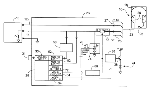
[0007] FIG. 1 is an apparatus for conserving battery power in a battery
operated
accessory which is connectable to an audio source via an electrical conductor;
[0008] FIG. 2 is a flow chart representing an algorithm that is used in a
micro-
controller of Fig. 1;
-2-
CA 02676772 2009-07-27
WO 2008/100919 PCT/US2008/053698
100091 FIG. 3 discloses an excitation current waveform that can be used in the
apparatus of Fig. 1; and
1000101 FIG. 4 discloses a portion of the excitation current waveform of Fig.
3.
DETAILED DESCRIPTION
[00011] Embodiments below describe controlling the operational state of a
battery
powered headset or other accessory depending on (a) the state of the
connection of the
headset with an external audio source such as an aviation intercom, and (b)
whether or
not the intercom is powered up. This can be done by sensing a voltage on the
connection
when a known electrical current is injected into the connection. When the
measured
voltage meets a predetermined condition, indicating the headset is not
connected to the
intercom or the intercom is powered off, battery power to the headset is
reduced to
conserve battery power. The headset can be placed in a standby or sleep mode
by
reducing the battery output power to a low level. Standby mode allows the
headset to
quickly "wake up" when necessary. Alternatively, the battery power can be
reduced to
zero which turns the headset completely off.
[00012] With reference to Fig. 1, an audio source 10 in this embodiment is an
aviation
intercom system that pilots use to communicate with, for example, each other
and ground
control. Audio source 10 can alternatively be a cell phone, MP3 player, CD
player,
portable DVD player or any other source of audio signals. These other types of
audio
sources can be powered with batteries, a vehicle electrical system, or a
conventional
household electrical system. Intercom 10 is electrically powered by the
airplane in which
it resides. An electrical conductor 12 and an electrical conductor 14
electrically couple
intercom 10 with other elements including an accessory 16. Conductor 14 is
capable of
conducting a first electrical signal, containing audio information from the
intercom 10, to
the accessory. Intercom 10 has an output impedance and provides an electrical
load on
conductor 14. Accessory 16 in this embodiment is an aviation headset which
includes a
band 18, two earcups 20 and a microphone 22. Accessory 16 can alternatively be
a
-3-
CA 02676772 2009-07-27
WO 2008/100919 PCT/US2008/053698
powered speaker or other device that uses battery power and receives audio
signals. Each
earcup 20 includes a speaker (not shown) for transmitting audio information to
the wearer
of headset 16. Active noise reduction (ANR) circuitry (not shown) is also part
of the
headset and is preferably located in one or both of earcups 20. As is well
known to those
skilled in the art, the ANR circuitry causes the speakers to output an
acoustic signal
which approximates the ambient noise present in the vicinity of headset 16,
the output
acoustic signal having approximately opposite polarity and equal amplitude
compared to
the noise signal. This has the effect of canceling the ambient noise within
earcups 16.
[00013] An electrical conductor 23 from headset 16 enters into a battery and
control
module 26. Conductor 23 actually includes four separate electrical conductors
which are
shown within module 26. A first one of these conductors is conductor 12
(described
above) through which audio information is transmitted from microphone 22 to
intercom
10. In this embodiment conductor 12 passes through module 26 without
electrically
interfacing with any components in the module. A second one of these
conductors is
conductor 14 (described above) through which audio information is transmitted
from
intercom (audio source) 10 to headset 16. A third one of these conductor is a
common
conductor 25 (ground). A fourth one of these conductors is conductor 27
through which
electrical power from a battery 24 is supplied to the ANR circuitry in headset
16. In this
embodiment battery and control module 26 is shown as a separate component from
intercom 10 and headset 16. It should be noted that some or all of the
components in
module 16 can alternatively be included in intercom 10 and/or headset 16.
[00014] Referring now to Figs. 1 and 2, a micro-controller 28 controls
operation of
module 26. The flow chart shown in Fig. 2 represents an algorithm that is run
by micro-
controller 28. An overview of how this algorithm operates is as follows. The
micro-
controller detects when a power button 31 is pressed to turn on module 26.
When
module 26 is turned on, battery power is immediately supplied to headset 16.
This
arrangement provides the user with ANR even if lines 12 and 14 have not yet
been
plugged into intercom 10, and if intercom 10 is not yet powered up. The
algorithm waits
a period of time to allow the electronics in module 26 to settle, the headset
user to plug
into intercom 10, and the user to power up the intercom. The algorithm then
checks to
-4-
CA 02676772 2009-07-27
WO 2008/100919 PCT/US2008/053698
see if a first electrical signal containing audio information from the audio
source is being
transmitted from the audio source to the headset on an electrical conductor.
When no
such first electrical signal is detected on the conductor for a set time
period, a second
electrical signal is injected into the electrical conductor. An aspect of the
second
electrical signal such as voltage on the conductor is measured. If the
measured voltage is
at or above a predetermined level, this indicates that the intercom is powered
off or that
the headset is disconnected from the intercom. In this case, battery power to
the headset
is reduced, preferably to zero, to conserve battery power. A particular
operation of one
embodiment is described in more detail below.
[00015] In a block 30 the logic detects that a user of the module and headset
16 has
turned on the module by pressing switch 31. The signal from the switch is
passed into
the micro-controller by an analog input 3 identified by a reference numera133.
At a
block 32 the logic initializes all inputs and outputs to an initial function,
and sets all
timers to zero. This includes having a logic output 3, identified by reference
numeral 34,
instruct a battery switch control 36 to close a switch 38 if it is not already
closed. As
such, battery power is supplied to the ANR or other active circuitry in
headset 16. At a
block 40 the logic starts a standby timer and at a block 42 it is determined
whether the
standby time is up. In this embodiment the standby time is preferably 3
minutes. The
standby time gives the circuitry time to settle and also allows time for the
user to plug
headset 16 into intercom 10 and turn on the intercom power.
[00016] When the standby time has expired, a real time clock (RTC) is started
at a
logic block 44. At a block 46 the logic determines whether or not an RTC
interrupt has
occurred. In this embodiment an RTC interrupt is generated about every 1.2
seconds.
Once an RTC interrupt is generated, a logic block 48 causes microcontroller 28
to sample
the peak audio signal on conductor 14. The peak audio signal is detected by an
amplitude
detector 50 which measures a voltage on conductor 14. The measured voltage is
passed
into the microcontroller via an analog input 1 identified by reference numeral
52. At a
logic block 54 it is checked whether or not the peak audio is greater than
Vth. In this
embodiment Vth is preferably about 50mV. When Vth is greater than 50mV it
indicates
the presence of an audio signal on conductor 14 and a logic block 56 sets "No
Audio
-5-
CA 02676772 2009-07-27
WO 2008/100919 PCT/US2008/053698
Count" to zero and returns to block 46. When Vth is not greater than 50mV a
logic block
58 sets "No Audio Count"= "No Audio Count"+l. At a logic block 60 it is
checked
whether "No Audio Count"= Maxl. In this embodiment Maxl is preferably set at
10.
When "No Audio Count" has not reached Maxl the logic returns to block 46. When
"No
Audio Count" has reached Maxl the logic proceeds to a logic block 62. The
logic
described in this paragraph determines whether or not there has been no
substantial audio
signal on conductor 14 for about 12 seconds. If there is an audio signal
(electrical signal
greater than 50mV) on conductor 14 within about 12 seconds the subroutine does
not
proceed further.
[000171 At logic block 62 a "Mute" output is set to high by microcontroller 28
through
a logic output 2 identified by reference numeral 64. A level converter 66
converts the 2.7
volt signal from logic output 2 into a -6 volt signal which causes a mute
switch 68
(preferably a J Fet transistor) to open. The result is an increase in
impedance between an
electrical current source 74 and headset 16. This temporarily hinders any
first electrical
signals from intercom 10 and an excitation current pulse (second electrical
signal) from
current source 74 (explained further below) from reaching the speakers in
earcups 20 of
headset 16. At a logic block 70 Ie is set to high which is output as a 2.7
volt signal at a
logic output 1 identified by a reference numera172. Electrical current source
74 converts
the 2.7 volt signal into a square pulse of electrical current (see element 76)
which is
injected into conductor 14. The current pulse is preferably at about 100uA. At
a logic
block 78 a time delay of preferably about 200uS occurs to allow the circuit to
settle. At a
logic block 80 a voltage Vs on conductor 14 is sampled (measured) and input
into
microcontroller 28 via an analog input 2 identified by a reference numeral 82.
At a logic
block 84 le is set to low which causes current source 74 to stop injecting
electrical current
into conductor 14. At a logic block 86 the "Mute" output is set to low which
causes mute
switch 68 to close. Mute switch 68 is opened is so that a wearer of headset 16
does not
hear an audible noise (e.g. click) when the current pulse is injected into
conductor 14.
[000181 The measured voltage in block 80 is related to an impedance Z of
conductor
14. This impedance may or may not include an output impedance of a powered up
or
powered down intercom 10 depending on whether or not conductor 14 is connected
to
-6-
CA 02676772 2009-07-27
WO 2008/100919 PCT/US2008/053698
intercom 10. We are thus determining an electrical characteristic of conductor
14.
Impedance is calculated as Z = V/le. By knowing the impedance we can determine
(a)
whether or not conductor 14 is connected to intercom 10, and (b) whether or
not intercom
is powered up when conductor 14 is connected to the intercom. When conductor
14 is
not connected to intercom 10, the sampled voltage is about 2.7 volts (the
maximum
voltage from current source 74 into the open circuit). A measured voltage of
about 2.7
volts indicates an infinite impedance. When conductor 14 is connected to an
unpowered
intercom 10, the sampled voltage is about 50mV. With an le of 100uA this
yields an
output impedance of intercom 10 of about 500Ohm. Finally, when conductor 14 is
connected to an electrically powered intercom 10, the sampled voltage is below
about
5mV. With an le of 100uA this yields an impedance of below about 500hm. When
conductor 14 is connected to a powered down intercom or disconnected from the
intercom for a set period of time, switch 38 will be opened to shut off the
ANR active
electronics and conserve battery power. This will be explained further below.
[00019] At a logic block 88 it is checked whether Vs > Vth. In this embodiment
Vth is
preferably about 50mV. When this predetermined condition is not met a "NoConn
Counter" (i.e. no connection or connected to unpowered intercom) is set to
zero at a
block 90 and the logic retums to a block 46. When the predetermined condition
is met
"NoConn Counter" value is increased by 1 at a logic block 92. When Vs > 50mV
it
indicates that either (a) conductor 14 is not connected to intercom 10, or (b)
conductor 14
is connected to a powered down intercom 10. At a logic block 94 it is checked
whether
"NoConn Counter"= Max2. If this condition is not met the logic cycles back to
block 46.
If this condition is met the logic proceeds to a block 96 where
microcontroller 28
instructs switch contro136 via logic output 3 to open switch 38. In this
embodiment,
battery power from battery 24 to headset 16 is reduced to zero, thereby
shutting of the
ANR circuitry. Alternatively, the battery power can be reduced to a lower
level above
zero such that the headset is put into a standby or sleep mode. Being in
standby mode
allows headset 16 to "wake up" quicker. The operating state of the headset is
thus
adjusted automatically. The operating state of the headset can be adjusted by
(a)
reducing battery power to the headset, (b) turning off the battery power to
the headset, (c)
placing the headset in a standby or sleep mode, and (d) altering another
electrical aspect
-7-
CA 02676772 2009-07-27
WO 2008/100919 PCT/US2008/053698
of the headset. Max2 here is chosen so that preferably about 3 minutes of time
must
elapse with substantially no audio signal on conductor 14 and, intercom 10
being
powered down or conductor 14 disconnected from intercom 10, before switch 38
is
opened. Since RTC timer generates an interrupt every 1.2 seconds, Max2 can
preferably
be about 150. The subroutine of Fig. 2 ends at a logic block 98.
[00020] Turning now to Figs. 3 and 4, an alternate current pulse will be
discussed that
can be used in place of the square pulse described above. In Fig. 3 it can be
seen that the
duration of the pulse is preferably about 1.6 seconds. The shape of this pulse
is similar to
a bell shaped curve. Fig. 4 shows a small piece of Fig. 3 near the 1000
millisecond
portion of the curve and near the top of the curve. The signal is preferably
an AC signal
having a frequency that is above an upper frequency cutoff point of the
headset. This
cutoff point represents the highest frequency audio signal that can be
reproduced by the
speakers in headset 16. For example, the upper frequency cutoff point of
headset 16
might be 15kHz. Fig. 3 shows that in this embodiment the signal is made up of
a large
number of square pulses that are occurring at preferably about 22kHz (above
the audible
range). This signal allows mute switch 68 (Fig. 1) to be eliminated because
the signal
cannot be heard by a wearer of headset 16 even if mute switch 68 is closed.
Further,
because an impedance of headset 16 (about 4.7kOhm) is much higher than the
impedance
of intercom 10, most of the second electrical signal current pulse will travel
into intercom
when conductor 14 is plugged into the intercom. As an alternative to the
square
pulses shown in Fig. 4, the signal can be in the form of a sine wave. A still
further
alternative of the signal involves having the signal alternate between
positive and
negative current during each cycle of the signal.
[00021] In an alternative embodiment of the invention, a user of the intercom
and
headset can disable the auto-off feature by, for example, pressing switch 31
for a set
period of time (e.g. 3 seconds) when turning on the module. This action causes
the
microcontroller to ignore the logic sequence shown in Fig. 2. When the user
presses
switch 31 again to shut off the module, the disable feature is also shut off.
-8-
CA 02676772 2009-07-27
WO 2008/100919 PCT/US2008/053698
[00022] In another embodiment of the invention, current source 74 is replaced
with a
constant voltage source, and the current on conductor 14 is measured instead
of the
voltage. Alternatively, the current source can be replaced by an electrical
source that
does not output a constant voltage or current. In this case both current and
voltage are
measured on conductor 14 to determine if the predetermined condition is met.
-9-