Language selection

Search

Patent 2677239 Summary

Third-party information liability

Some of the information on this Web page has been provided by external sources. The Government of Canada is not responsible for the accuracy, reliability or currency of the information supplied by external sources. Users wishing to rely upon this information should consult directly with the source of the information. Content provided by external sources is not subject to official languages, privacy and accessibility requirements.

Claims and Abstract availability

Any discrepancies in the text and image of the Claims and Abstract are due to differing posting times. Text of the Claims and Abstract are posted:

  • At the time the application is open to public inspection;
  • At the time of issue of the patent (grant).
(12) Patent: (11) CA 2677239
(54) English Title: SURGICAL NAVIGATION SYSTEM FOR GUIDING AN ACCESS MEMBER
(54) French Title: SYSTEME DE NAVIGATION CHIRURGICALE SERVANT A GUIDER UN ELEMENT D'ACCES
Status: Granted
Bibliographic Data
(51) International Patent Classification (IPC):
  • A61B 34/20 (2016.01)
  • A61B 17/17 (2006.01)
  • A61B 17/34 (2006.01)
(72) Inventors :
  • PATWARDHAN, RAVISH V. (United States of America)
(73) Owners :
  • INTERACTIVE NEUROSCIENCE CENTER, LLC (United States of America)
(71) Applicants :
  • INTERACTIVE NEUROSCIENCE CENTER, LLC (United States of America)
(74) Agent: SMART & BIGGAR LP
(74) Associate agent:
(45) Issued: 2016-06-21
(86) PCT Filing Date: 2008-02-01
(87) Open to Public Inspection: 2008-08-07
Examination requested: 2012-12-11
Availability of licence: N/A
(25) Language of filing: English

Patent Cooperation Treaty (PCT): Yes
(86) PCT Filing Number: PCT/US2008/052790
(87) International Publication Number: WO2008/095166
(85) National Entry: 2009-07-31

(30) Application Priority Data:
Application No. Country/Territory Date
60/887,719 United States of America 2007-02-01
60/942,261 United States of America 2007-06-06

Abstracts

English Abstract

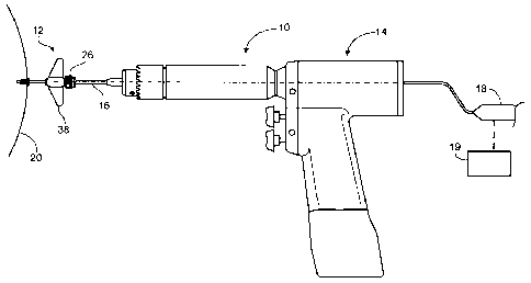
A method of surgical navigation into' the brain includes establishing a trajectory through the skull into the brain to a target, drilling a hole in the skull using a drill (14), and verifying the trajectory of the drilled hole during drilling using image guidance. A surgical navigation system includes a cannulated drill, a cannulated access member (30), and a coupling member (16) for coupling the access member to the drill and for maintaining alignment of the cannulations in the drill and the access member. The access member is movable relative to the coupling member such that the access member can be secured to tissue while the coupling member maintains the alignment of the cannulations. A surgical kit includes a cannulated drill, a cannulated access member, a coupling member for coupling the access member to the drill, and a probe for receipt within the cannulated drill.


French Abstract

L'invention concerne un procédé de navigation chirurgicale dans le cerveau comprenant l'établissement d'une trajectoire par le crâne dans le cerveau jusqu'à une cible, le perçage d'un trou dans le crâne en utilisant un foret (14) et la vérification de la trajectoire du trou foré pendant le forage en utilisant le guidage par image. Un système de navigation chirurgicale comprend un foret tubulaire, un élément d'accès tubulaire (30) et un élément de couplage (16) pour coupler l'élément d'accès au foret et pour maintenir l'alignement des tubes du foret et de l'élément d'accès. L'élément d'accès peut se déplacer par rapport à l'élément de couplage de sorte que l'élément d'accès peut être fixé au tissu tandis que l'élément de couplage maintient l'alignement des tubes. Un nécessaire chirurgical comprend un foret tubulaire, un élément d'accès tubulaire, un élément de couplage pour coupler l'élément d'accès au foret, ainsi qu'une sonde logée dans le foret tubulaire.

Claims

Note: Claims are shown in the official language in which they were submitted.


Claims

1. A guided system comprising an access member for establishing a
trajectory to a target
by securement to a tissue, wherein the guided system further comprises: a
cannulated drill
having a length; a coupling member for coupling the access member to the drill
during
securement of the access member to the tissue; and, a probe disposed within
the cannulated
drill and extending about half the length of the drill; wherein said probe is
adapted to guide
alignment of the access member to said trajectory.
2. The system of claim 1 wherein said coupling member maintains alignment
of the
cannulated drill with a lumen in the access member.
3. The system of claim 1 or 2 further comprising a drill bit attached to
said drill.
4. The system of claim 3 wherein said drill bit is adapted for drilling a
pilot hole into said
tissue.
5. The system of any one of claims 1 to 6, wherein said access member
comprises a
clamping member for clamping onto a device received within a lumen in the
clamping member.
6. The system of any one of claims 1 to 5, wherein said access member
comprises a main
body having a proximal portion with two outwardly extending wings.
7. The system of any one of claims 1 to 4, wherein said access member
comprises a
clamping member for clamping onto a device received within a lumen in the
clamping member;
and wherein said clamping member comprises a threaded extension to be received
by a
proximal portion of a main body of said access member and is rotatable
relative to said main
body.


8. The system of claim 6 or 7, wherein said main body has a distal portion
surrounded by a
depth stop, said depth stop being adapted for setting the depth to which the
access member is
insertable into said target.
9. The system of any one of claims 1 to 8, further comprising a medical
device for
introduction to the target through said access member.
10. The system of claim 9, operable by navigation software determines depth
of
advancement of the medical device.
11. The system of claim 9 or 10, wherein said medical device comprises a
ventriculostomy
catheter, convertion therapy catheter, epilepsy depth electrode,
thermocoagulation probe,
lesioning probe, stereotactic needle or ablative probe.
12. The system of any one of claims 1 to 11, wherein the tissue is a skull.
13. The system of any one of claims 1 to 12, wherein said probe is coupled
to an image-
guidance system.
14. The system of claim 13, wherein said image-guidance system tracks a
trajectory of the
probe relative to images of a patient.
15. The system of any one of claims 1 to 14, comprising a robot arm for
supporting the
cannulated drill.
16. The system of any one of claims 1 to 15, further comprising a robot arm
adapted for
fixing the position of said cannulated drill in a selected axis.

6

Description

Note: Descriptions are shown in the official language in which they were submitted.


CA 02677239 2016-01-21
CA2677239
SURGICAL NAVIGATION SYSTEM FOR GUIDING AN ACCESS MEMBER
TECHNICAL FIELD
This invention disclosure relates to surgical navigation.
SUMMARY
A method of surgical navigation into the brain includes establishing a
trajectory through the
skull into the brain to a target, drilling a hole in the skull using a drill,
and verifying the trajectory of the
drilled hole during drilling using image guidance.
Embodiments of this aspect may include one or more of the following features.
The image
guidance is provided by a probe received by the drill. The probe is received
in a lumen defined by the
drill. The method includes placing an access member in the drilled hole, and
verifying the trajectory of
the access member during placement. The access member is placed using the
drill, and the trajectory is
verified using the probe received by the drill.
Various embodiments of the claimed invention relate to a guided system
comprising an access
member for establishing a trajectory to a target by securement to a tissue,
wherein the guided system
further comprises: a cannulated drill having a length; a coupling member for
coupling the access
member to the drill during securement of the access member to the tissue; and,
a probe disposed within
the cannulated drill and extending about half the length of the drill; wherein
said probe is adapted to
guide alignment of the access member to said trajectory.
A surgical navigation system may include a cannulated drill, a cannulated
access member, and a
coupling member for coupling the access member to the drill and for
maintaining alignment of the
cannulations in the drill and the access member. The access member is movable
relative to the coupling
member such that the access member can be secured to tissue while the coupling
member maintains the
alignment of the cannulations.
1

CA 02677239 2016-01-21
CA2677239
Embodiments of this aspect may include one or more of the following features.
The system
includes a probe for receipt within the cannulated drill. The system includes
a drill bit.
A surgical kit includes a cannulated drill, a cannulated access member, a
coupling member for
coupling the access member to the drill, and a probe for receipt within the
cannulated drill.
Embodiments of this aspect may also include a drill bit, a medical device,
and/or a robot arm.
Various embodiments of the claimed invention relate to a system comprising: an
access member
having, a main body defining a first lumen extending from a proximal end to a
distal end of the main
body, the proximal end having a first coupling region and the distal end
having a second coupling
region; a clamping member coupled to the first coupling region and defining a
second lumen aligned
with the first lumen; and a collet at the proximal end of the main body
configured to secure a device
received in the first and second lumens; wherein the second coupling region is
configured to be coupled
to a bone of a patient and the proximal end is configured to receive a medical
device through the second
lumen of the clamping member and the first lumen of the main body.
DESCRIPTION OF DRAWINGS
FIG. 1 is an illustration of a cannulated drill being used to place an access
member in the skull
under navigation guidance.
FIG. 2 is a partial cross-sectional view of the access member.
FIG. 3 is a side view of a coupling member that couples the access member to
the cannulated drill.
FIG. 4 shows the cannulated drill being used to drill a hole in a skull.
FIG. 5 shows the access member being used to position a medical device at a
target site within the
brain.
FIG. 6 illustrates an exemplary disposable kit containing components of the
system.
FIG. 7 illustrates a robot arm supporting the cannulated drill.
2

CA 02677239 2014-07-30
DETAILED DESCRIPTION
The details of one or more embodiments of the invention are set forth in the
accompanying drawings and the description below. Various features and
advantages of the
invention will be apparent from the following description and the accompanying
drawings.
Referring to Fig. 1, an image-guided trajectory system 10 includes an access
member 12
for establishing a set trajectory to a target site, a cannulated drill 14, and
a coupling member
rod 16 that couples the access member 12 to the cannulated drill 14 during
securement of the
access member 12 to a patient's skull 20. Also shown in Fig. 1 is a probe 18,
for example, a
BrainLab Probe (available from BrainLab Cranial Navigation System) or an
Integra Probe
(available from Integra LifeSciences), received within the drill 14 and
extending about half-
way down the length of the drill 14. The probe 18 is coupled to an image
guidance system 19,
for example, a BrainLab image guidance system or an Integra image guidance
system, which
tracks the trajectory of the probe 18 relative to images of a patient's brain.
The receipt of the
probe 18 within the cannulated drill 14 during securement of the access member
12 to the skull
20 insures that the access member 12 establishes the desired trajectory to a
target site.
Referring to Fig. 2, the access member 12 includes a main body 22 defining an
internal
lumen 24, and a clamping member 26 defining an internal lumen 28 aligned with
lumen 24.
The main body 22 has a distal portion 30 with a threaded region 32 that
engages the skull bone
to secure the access member to the skull 20. Surrounding the distal portion 30
is a depth stop 34
that sets the depth to which the access member 12 is insertable into the
skull. The main body 22
has a proximal portion 36 with two outwardly extending wings 38 that can be
engaged by the
operator's hand and turned to thread the access member 12 into the
2a

CA 02677239 2009-07-31
WO 2008/095166
PCT/US2008/052790
skull. The main body 22 has a proximal portion 36 with two outwardly extending
wings 38
that can be engaged by the operator's hand and turned to thread the access
member 12 into
the skull.
The clamping member 26 has a threaded extension 40 that is received by the
proximal
portion 36 of the main body 24 and is rotatable relative to the main body 24.
The clamping
member 26 acts on a collet 42 located within proximal portion 36 such that
rotation of the
clamping member 26 causes the collet 42 to clamp onto and release the rod 16
(Fig. 3)
received in the lumens 24 and 28.
Referring to Fig. 4, prior to securing the access member 12 to the skull 20,
the
operator uses the cannulated drill 14 to drill a pilot hole 60 in the skull
20. Using a drill bit
62 and with the probe 18 received within the drill 14, the operator drills the
pilot hole 60
under image guidance such that the pilot hole 60 is aligned with a desired
preplanned
trajectory to a target set within the brain. Surrounding the drill bit 62 is a
movable depth stop
64 that sets the depth to which the drill bit 62 is insertable into the skull.
After drilling the pilot hole, the operator replaces the drill bit 62 with the
rod 16 and
attached access member 12, a shown in Fig. 1. The rod 16 extends about 3.5 cm
into the drill
14 and about 3.5 cm into the access member 12 to axially align the drill 14
and the access
member 12. The operator places the access member 12 against the entrance to
the pilot hole
60 and uses the probe 18 to align the access member 12 along the desired
trajectory to the
target site. The operator then loosens the collet 26 such that the access
member 12 can be
rotated relative to the rod 16 to advance the access member 12 into the skull
20. While the
rod remains attached to the drill 14 and remains within the lumens 24, 28
during rotation of
the access member 12, the rod 16 need not move, that is, is not rotated,
during the
advancement of the access member 12. While applying a force to the wings 38 to
thread the
access member 12 into the skull 20, the operator verifies the alignment of the
access member
12 along the trajectory using probe 18 positioned within drill 14.
The operator then removes the drill 14 and rod 16 from the access member 12.
Referring to Fig. 5, the access member 12 now establishes a set trajectory for
introduction of
various medical devices 70, e.g., ventriculostomy catheters, other directed
catheters for
convection therapy, epilepsy depth electrodes, thermocoagulation probes,
lesioning probes,
stereotactic needles, and ablative probes, to the target site 72. The operator
need only control
3

CA 02677239 2014-07-30
'
the depth of advancement of the medical device, which, in many cases, can be
predetermined
using navigation software.
To further increase the accuracy of the device placement through the access
member
12, the drill 14 can directly hold the access member after securement of the
access member to
the skull 20, and the medical device can be passed through the drill and the
access member to
the target site.
A cannulated drill is available from Stryker (4200 Cordless Driver 2), and can
be
used with a step down chuck for holding the drill bit 62 and the rod 16.
The various components of the image-guided trajectory system 10 can be sold as
kits
80 (Fig. 6), either disposable or non disposable, including one or more
components of the
system 10. For example, the cannulated drill 14, the access member 12, the
coupling
member 16, and the drill bit 62 can be packaged together for sale as a
disposable kit.
Alternatively, any combination of one or more of the four components can be
packaged
together for sale as a disposable kit, for example, just the access member 12,
the coupling
member 16, and the drill bit 62 can be packaged together, the access member 12
and the
coupling member 16 can be packaged together, etc. The probe 18 can also be
included in
any of the various combinations of disposable kits described above, for
example, a
disposable kit can include the probe 18, drill 14, access member 12, and
coupling member
16. Furthermore, one or more medical devices 70 can be included in any of the
various
combinations of disposable kits, including kits with the probe 18. All of the
components
need not be disposable. The various components can be sold as a system with
the image
guidance system 19.
Referring to Fig. 7, the cannulated drill 14 can be supported during use by a
robot arm
82, for example, a BrainLab robot arm. The robot arm 82 can be manipulated to
fix the
position of the cannulated drill 14 in a selected axis. The robot arm 82 is
preferably
supported by a device 84, for example, a Mayfield head holder, used to fixate
the head. The
robot arm 82 can be included in any of the kit configurations described above.
Various modifications may be made without departing from the scope
of the
invention.
4

Representative Drawing
A single figure which represents the drawing illustrating the invention.
Administrative Status

For a clearer understanding of the status of the application/patent presented on this page, the site Disclaimer , as well as the definitions for Patent , Administrative Status , Maintenance Fee  and Payment History  should be consulted.

Administrative Status

Title Date
Forecasted Issue Date 2016-06-21
(86) PCT Filing Date 2008-02-01
(87) PCT Publication Date 2008-08-07
(85) National Entry 2009-07-31
Examination Requested 2012-12-11
(45) Issued 2016-06-21

Abandonment History

Abandonment Date Reason Reinstatement Date
2015-05-21 FAILURE TO PAY FINAL FEE 2015-07-02

Maintenance Fee

Last Payment of $254.49 was received on 2022-01-19


 Upcoming maintenance fee amounts

Description Date Amount
Next Payment if small entity fee 2023-02-01 $253.00
Next Payment if standard fee 2023-02-01 $624.00

Note : If the full payment has not been received on or before the date indicated, a further fee may be required which may be one of the following

  • the reinstatement fee;
  • the late payment fee; or
  • additional fee to reverse deemed expiry.

Patent fees are adjusted on the 1st of January every year. The amounts above are the current amounts if received by December 31 of the current year.
Please refer to the CIPO Patent Fees web page to see all current fee amounts.

Payment History

Fee Type Anniversary Year Due Date Amount Paid Paid Date
Application Fee $400.00 2009-07-31
Registration of a document - section 124 $100.00 2010-01-11
Maintenance Fee - Application - New Act 2 2010-02-01 $100.00 2010-01-20
Maintenance Fee - Application - New Act 3 2011-02-01 $100.00 2011-01-31
Maintenance Fee - Application - New Act 4 2012-02-01 $100.00 2011-11-01
Maintenance Fee - Application - New Act 5 2013-02-01 $200.00 2012-12-10
Request for Examination $800.00 2012-12-11
Maintenance Fee - Application - New Act 6 2014-02-03 $200.00 2014-01-24
Maintenance Fee - Application - New Act 7 2015-02-02 $200.00 2015-01-22
Reinstatement - Failure to pay final fee $200.00 2015-07-02
Final Fee $300.00 2015-07-02
Maintenance Fee - Application - New Act 8 2016-02-01 $200.00 2016-01-19
Maintenance Fee - Patent - New Act 9 2017-02-01 $200.00 2017-01-30
Maintenance Fee - Patent - New Act 10 2018-02-01 $250.00 2018-01-29
Maintenance Fee - Patent - New Act 11 2019-02-01 $250.00 2019-01-25
Maintenance Fee - Patent - New Act 12 2020-02-03 $250.00 2020-01-22
Maintenance Fee - Patent - New Act 13 2021-02-01 $255.00 2021-01-20
Maintenance Fee - Patent - New Act 14 2022-02-01 $254.49 2022-01-19
Owners on Record

Note: Records showing the ownership history in alphabetical order.

Current Owners on Record
INTERACTIVE NEUROSCIENCE CENTER, LLC
Past Owners on Record
PATWARDHAN, RAVISH V.
Past Owners that do not appear in the "Owners on Record" listing will appear in other documentation within the application.
Documents

To view selected files, please enter reCAPTCHA code :


To view images, click a link in the Document Description column. To download the documents, select one or more checkboxes in the first column and then click the "Download Selected in PDF format (Zip Archive)" or the "Download Selected as Single PDF" button.

List of published and non-published patent-specific documents on the CPD .

If you have any difficulty accessing content, you can call the Client Service Centre at 1-866-997-1936 or send them an e-mail at CIPO Client Service Centre.


Document
Description 
Date
(yyyy-mm-dd) 
Number of pages   Size of Image (KB) 
Abstract 2009-07-31 1 58
Claims 2009-07-31 2 45
Drawings 2009-07-31 5 53
Description 2009-07-31 4 213
Cover Page 2009-11-02 1 39
Representative Drawing 2009-11-02 1 5
Description 2014-07-30 5 215
Claims 2014-07-30 2 63
Description 2015-07-02 5 243
Claims 2015-07-02 6 184
Claims 2016-01-21 2 66
Description 2016-01-21 5 231
Representative Drawing 2016-04-27 1 4
Cover Page 2016-04-27 1 41
Correspondence 2010-02-24 1 15
PCT 2009-07-31 5 226
Assignment 2009-07-31 4 105
Correspondence 2009-10-08 1 19
Correspondence 2009-10-30 2 58
Assignment 2010-01-11 6 189
PCT 2010-07-13 1 49
Fees 2011-01-31 1 36
Fees 2011-11-01 1 68
Fees 2012-12-10 1 67
Prosecution-Amendment 2014-07-30 9 360
Prosecution Correspondence 2016-01-22 3 103
Prosecution-Amendment 2012-12-11 2 75
Fees 2014-01-24 2 77
Prosecution-Amendment 2014-01-31 3 96
Correspondence 2015-02-17 4 231
Amendment after Allowance 2015-07-02 2 92
Amendment after Allowance 2015-07-02 7 258
Examiner Requisition 2015-07-21 4 259
Prosecution-Amendment 2016-01-21 7 269