Note: Descriptions are shown in the official language in which they were submitted.
CA 02677346 2012-08-21
WO 2008/097947 PCT/US2008/053016
DOWN HOLE ELECTRICAL CONNECTOR FOR COMBATING RAPID
DECOMPRESSION
TECHNICAL FIELD
[0002] The present invention relates to an electrical cable connector
apparatus and
method for an underground well. More particularly, the present invention
relates to a simplified,
low cost down hole electrical connector, and method for blocking well fluids
from entering the
connector and escaping through electrical cable assembly to hazardous areas.
BACKGROUND OF THE INVENTION
[0003] Substantial difficulty has heretofore been encountered in providing a
down
hole connector assembly that prevents well fluids from permeating the
connector and electrical
cable assembly. Fluid entering the connector can cause electrical faults in
the connector itself,
and can also escape through permeable portions of the electrical cable
assembly into low
pressure hazardous areas such as electrical enclosures within the well, above
ground areas near
the wellhead barrier, and even to the power transformer. Explosions or fires
may occur in
hazardous areas due to gases and other substances associated with the
production of petroleum
products being ignited by electric arcs. This endangers personnel and the
general public by
creating risk of electrical shock or death by electrocution in or near the
hazardous area.
[0004] So far as known to applicant, the current art has failed to overcome
the
above and other problems. A substantial need therefore exists to provide a
satisfactory and safe
method and apparatus for supplying electrical power from an above ground power
source,
through hazardous areas, and into a well where down hole electrical
connections are made.
1
CA 02677346 2009-08-05
WO 2008/097947 PCT/US2008/053016
[0005] Present commonly employed electrical installations typically
comprise a
flexible corrugated housing with an internal electrical conductor means, such
as an insulated
conductive wire, that extends from the above ground power source through the
wellhead barrier
and into the well. It is substantially difficult, if not impossible, to
initiate and/or maintain an
effective seal where the corrugated cable passes through the wellhead barrier
to prevent fluid
discharge from the well. It is also substantially difficult to seal the
internal elements of a down
hole connector and electrical cable from being permeated by well fluids.
[0006] The above mentioned problems worsen when pressure changes occur in the
well. Although pressure changes caused by the formation can by regulated to
some extent by the
electrical submersible pump ("ESP"), when the ESP is turned off, the well can
reach pressures at
the wellhead in excess of 5,000 to 10,000 pounds per square inch. The high
pressure forces well
fluids to penetrate seams or gaps in the connector and saturate permeable
materials, such as the
rubber boot of the connector and conductive wire insulation. Once the
insulation is permeated,
the fluid can flow through the electrical cable and out into hazardous areas
creating a potentially
explosive situation.
[0007] Currently known electrical installations have attempted to overcome
the
above mentioned problems by providing a connector made with an external
protective sleeve that
protects the internal rubber boots of the connector and prevents their outward
expansion. The
protective sleeve itself is typically comprised of two mating parts that allow
the connection to be
disconnected. However, even if the two parts of the shield are fastened or
otherwise locked
together, as is typical, the pressure differentials in the well often cause a
piston effect between
the rubber boots that forces the electrical connection apart. It is therefore
desirable to provide a
connector capable of remaining intact during pressurization and
depressurization within the well.
[0008] Other electrical installations, such as those described in U.S. Pat.
No.
4,614,392, Boyd B. Moore (the '392 patent"), have attempted to solve the above
mentioned
problems with connectors positioned next to or inside of the encapsulated
pressurized areas of
the well. The '392 patent, for example, discloses how to seal electrical
conductor wires that pass
through a packer inside of steel tubes in order to provide conduction from a
low pressure area
above the packer to a high pressure area below the packer. In the '392, on
either side of the
packer, the steel tubes terminate using a known coupling assembly and
insulator stand off
provides the means to electrically isolate the crimp sleeve/connector socket
joining the two
2
CA 02677346 2009-08-05
WO 2008/097947 PCT/US2008/053016
conductor wires. It has been discovered, however, that in certain applications
well fluids may
penetrate the insulator stand off surrounding the connector socket and reach
the conductive wire.
Such fluid penetration causes the fluid to slowly escape to the low pressure
area and into contact
with the conductors. It is desired, therefore, to provide a more effective
fluid seal, so that
connectors placed in or near down hole pressurized areas will not leak fluids
to low pressure
areas.
[0009] Other commonly employed electrical installations have attempted to
solve
the above mentioned problems while, at the same time, providing a connecter
than can be
disconnected if the well, down hole equipment, electrical assembly, or other
interconnected
structures need to be removed. These installations typically comprise a
connecter made with an
attachment plug and a receptacle. The plug and receptacle design selectively
connect and
disconnect to terminate the above ground power source to down hole equipment.
Under
applicable regulations and/or industry standards the attachment plug and
receptacle should have
the same power rating as the device to which power is being supplied. However,
so far as known
to applicant, the attachment plug and receptacle connectors do not have such a
rating and are
incapable of withstanding an internal explosion without risk to the operator
and drilling
operations.
[0010] Another problem
with the attachment plug and receptacle is that it
frequently fails to stay connected when the well is suddenly pressurized or
depressurized.
During pressurization the connector's internal rubber boots often become
impregnated with fluid
and expand, which may force apart the connector's mating counterparts.
During
depressurization, fluid impregnated rubber boots may fail to release the
fluids fast enough
resulting a disconnect. It is therefore desirable to provide a down hole
connector that can
selectively terminate the above ground power source with down hole equipment
that is not
adversely affected by well pressures. Alternatively, it is desirable to
provide a connector or an
electrical cable connection assembly that can be efficiently and inexpensively
cut off and
replaced by a new connector or electrical cable connection assembly without
substantial expense
to the operator or delay in well operations.
3
CA 02677346 2009-08-05
WO 2008/097947 PCT/US2008/053016
SUMMARY OF THE INVENTION
[0011] To overcome the above and other problems, the preferred embodiment of
the present invention includes a down hole connector that effectively seals
the connector and
internal elements of the electrical cable to prevent fluid discharge into
hazardous areas. The
preferred connector is sufficient to maintain a sealed mechanical and
electrical connection
between any two power cables, despite shifting and/or movement by the joined
cables and well
pressure events (pressurization and depressurization). The preferred connector
is formed with a
fluid sealing encasing material that surrounds and/or adheres to at least a
portion of a the
protective tubing surrounding an electrical cable's conductor wires. The
encasing material may
also surround and adhere to the conductive wire's insulation to prevent the
insulation from
changing physical dimensions during pressure events. A protective outer sleeve
is positioned
over the electrical cable so that it can engage the cable and be adhered to by
the encasing
material.
[0012] Another embodiment of the present invention employs a unique "hardwire
connector" and/or method which the wires are crimped together within the
connector.
Optionally, the hardwire connector is attached to a cable extension piece that
is made to be
replaceable. The connector can be uncoupled and/or cut off and replaced with
new connector
and extension pieces to re-terminate the conductor wires.
[0013] In another embodiment, a connector comprises a protective outer sleeve
for
receiving and engaging at least one protective tubing encapsulating a down
hole conductor wire;
and a seal formed between the protective tubing and the protective outer
sleeve; wherein the seal
comprises: an encasing material for adhering to the protective tubing and
protective outer sleeve
and preventing fluid from passing between the protective tubing, protective
outer sleeve and
encasing material. Optionally, the encasing material is positioned within the
connector to fill the
space between the protective outer sleeve and the protective tubing. The seal
may also restrict
outward expansion of a fluid permeable material encapsulating a down hole
conductor wire.
Optionally, the down hole electrical cable is a tube extension cable adapted
to selectively couple
with a separate down hole electrical cable. Additionally, a bottom stop
assembly is optionally
positioned at least partially within the protective outer sleeve and adjacent
to the encasing
material; wherein the bottom stop assembly is adapted to receive and engage
the protective
tubing. The seal may further comprise a relatively rigid connection for
impeding fluid flow;
4
CA 02677346 2009-08-05
WO 2008/097947 PCT/US2008/053016
wherein the seal is formed between the protective outer sleeve, bottom stop
assembly, and
protective tubing. The bottom stop assembly is optionally adapted for
receiving and engaging
the terminus of the protective tubing, and may such engagement may be
approximately two
inches from the terminus of the protective tubing.
[0014] In another embodiment of the present invention a connector comprises a
protective outer sleeve; a top stop assembly for receiving and engaging a
first down hole
electrical cable; wherein the top stop assembly is positioned at least
partially within the
protective outer sleeve; a bottom stop assembly for receiving and engaging the
protective tubing
of a second down hole electrical cable that electrically terminates with the
first down hole
electrical cable; wherein the bottom stop assembly is positioned at least
partially within the
protective outer sleeve; at least one insulating boot with an axial passage
for supporting a
terminated first and second down hole electrical cable within the protective
outer casing; and a
fluid tight seal for preventing fluid from entering the connector comprising
an encasing material
and a rigid connection; wherein the encasing material is affixed to protective
tubing of a second
electrical cable, bottom stop and protective outer sleeve, and the rigid
connection is formed
between the protective outer sleeve, bottom stop assembly, and protective
tubing of the second
electrical cable. Optionally, the insulating boot comprises a first male
insulating boot and a
separate second female insulating boot. The first down hole electrical cable
is optionally
penetrator cable; and the second down hole electrical cable is a pump cable.
[0015] In another embodiment, a method for providing the down hole connector
comprises the steps of: receiving and engaging at least one down hole
electrical cable with a
protective outer sleeve, wherein the down hole electrical cable is formed with
a conductor wire at
least partially encapsulated in protective tubing; and sealing the protective
outer sleeve and the
received and engaged at least one down hole electrical cable to impede well
fluid from entering
the connector; wherein the step of sealing comprises: affixing an encasing
material to the
protective tubing of the down hole electrical connector and to the protective
outer sleeve; and
forming a relatively rigid connection between the protective outer sleeve and
the protective
tubing of the down hole electrical cable. Optionally, the method further
comprises the step of
positioning a bottom stop assembly at least partially within a protective
outer sleeve and adjacent
to the encasing material so that the bottom stop assembly receives and engages
the down hole
electrical cable. The step of providing a down hole electrical cable
optionally involves providing
CA 02677346 2009-08-05
WO 2008/097947 PCT/US2008/053016
a first removable electrical cable extension piece. The method may further
comprise the steps of:
disconnecting the first removable electrical cable from any separate attached
down hole electrical
cables; replacing the first down hole electrical cable extension piece with a
second removable
down hole electrical cable extension piece; and repeating above mentioned
steps.
[0016] The foregoing has outlined the features and technical advantages of
the
present invention in order that the detailed description of the invention that
follows may be better
understood. Additional features and advantages of the invention will be
described hereinafter
which form the subject of the claims of the invention. It should be
appreciated by those skilled
in the art that the conception and specific embodiment disclosed may be
readily utilized as a
basis for modifying or designing other structures for carrying out the same
purposes of the
present invention. For example, embodiments of the connectors described herein
may be used to
join any type of cable, even though specific reference is made herein to down
hole penetrators,
pump cables, tube unions, main electrical cable, pothead cables, etc.
Accordingly, for avoidance
of doubt, the term cable, as used herein, includes any type of electrical
cable, including those
comprised of a conductive wire, insulation and/or protective tubing. The term
cable may
therefore refer to main electrical cable, pump cable, motor and extension
cable ("MLE"),
penetrator cable, and pothead cable, for example. In addition, the position of
the improved
connector within the well (although described herein as being positioned
above, below, or near a
packer or encapsulated pressurized area) may anywhere within or the well. It
should also be
realized by those skilled in the art that such equivalent constructions do not
depart from the spirit
and scope of the invention as set forth in the appended claims. The novel
features which are
believed to be characteristic of the invention, both as to its organization
and method of operation,
together with further objects and advantages will be better understood from
the following
description when considered in connection with the accompanying figures. It is
to be expressly
understood, however, that each of the figures is provided for the purpose of
illustration and
description only and is not intended as a definition of the limits of the
present invention.
DESCRIPTION OF THE DRAWINGS
[0017] For a more complete understanding of the present invention, reference
is
now made to the following descriptions taken in conjunction with the
accompanying drawings,
in which:
6
CA 02677346 2009-08-05
WO 2008/097947 PCT/US2008/053016
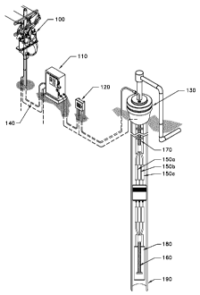
[0018] FIG 1 shows a surface power source providing electrical power into a
well
to power down hole equipment connected by an example connector of the present
invention;
[0019] FIG 2 shows a side view of an example female connector assembly,
attached to a three phase down hole electrical cable, and an example male
connector assembly,
attached to another down hole electrical cable, that can be plugged in and
engaged by a
protective outer sleeve;
[0020] FIG 3A and 3B are sectional views of an example connector in which a
male connector assembly is plugged into a female connector assembly and
secured within a
protective outer sleeve;
[0021] FIGS 4A and 4B show a partial sectional view of an example male
connector assembly;
[0022] FIGS 5A and 5B show sectional views of an example reusable hardwire
connector;
[0023] FIGS 6A, 6B, and 6C show additional example embodiments of a hardwire
reusable connector being installed on a penetrator; and
[0024] FIGS 7A, 7B, 7C, 7D, and 7E show an example sequence for installing an
example hardwire reusable connector on a penetrator.
DETAILED DESCRIPTION OF THE INVENTION
[0025] FIG 1 illustrates a preferred embodiment of the invention in which a
remote
surface power source 100 provides electrical power to down hole electrical
equipment. The
remote power source 100 is preferably a transformer bank, positioned on a
power pole, which
supplies power via cable 140 to motor control panel 110. Electrical cable 140
is typically
formed of a medium voltage electrical conductor cable that runs from the motor
control panel
110 in a known way to a vented junction box 120, and then into a wellhead
barrier 130 of an
underground well. Inside the well, cable 170 extends from the wellhead barrier
130 below to a
position down hole where an electrical connection will be made with a cable
using preferred and
alternative embodiments of the present invention. The connectors 150a, 150b,
and 150c that are
shown in FIG 1 are each individually shown in FIGS 1-8 as connector 150. The
connectors
7
CA 02677346 2009-08-05
WO 2008/097947 PCT/US2008/053016
provide the means for electrically and mechanically connecting cable 170 and
cable 160 inside
the well.
[0026] In typical installations, cable 170 extends down a substantial portion
of the
well to the operating depth where it connects with cable 160. The operating
depth preferably
ranges from 1,000 to 15,000 feet, however, there is no practical maximum
operating depth.
[0027] FIG 1 shows a preferred embodiment in which cable 170 is a main
electrical
cable that is mechanically and electrically connected with cable 160, the MLE
cable near the
operating depth. The main electrical cable may be banded to the production
tubing in a known
way as it extends down the drill casing. The MLE cable may also be banded to
the production
tubing, or the ESP assembly, or other down hole equipment in a known way.
[0028] Cable 170 and cable 160 are shown in FIG 2 in a side view. Cable 160
preferably includes three insulated conductor wires in protective tubing 260a,
260b, and 260c,
which may be fitted with either male connector assemblies 280a, 280b, 280c or
female connector
assemblies 250a, 250b, 250c. Preferably, cable 170 is fitted with the female
connector
assemblies as shown in FIG 2. Cable 170 is comprised of three insulated
conductor wires 270a,
270b, and 270c, each of which are electrically terminated at the surface power
source 100 (See
FIG 1) and fitted with either male connector assemblies 280a, 280b, 280c or
female connector
assemblies 250a, 250b, 250c. Preferably, the cable 170 is fitted with the male
connector
assemblies as shown in FIG 2. Cable 170 is preferably formed to exhibit a
round or flat lateral
dimension, as shown in Fig 2's cross sectional views.
[0029] A preferred embodiment of the down hole connector 150 is shown in FIGS
3A and 3B in a cross sectional view. The connector 150 is comprised of a top
stop assembly
340, female boot 370, and green hooter 320 (collectively the "female connector
assembly 260").
The connector 150 is also comprised of a conductor pin 390, male boot 380,
encasing material
375, bushing 362, and bottom stop assembly 360 (collectively the "male
connector assembly
280"). The connector 150 also includes a protective outer sleeve 240 that
protects and engages
the electrically terminated cables 160 and 170 and may be secured by stop
screws 310 to the
male and female connector assemblies.
[0030] One aspect of the connector is directed to the female connector
assembly
260. As shown in FIGS 3A and 3B, the female connector assembly is formed by
top stop
8
CA 02677346 2009-08-05
WO 2008/097947 PCT/US2008/053016
assembly 340 that secures and engages cable 160 with a compression fitting.
The compression
fitting preferably comprises a compression nut that tightens against a
threaded portion of top stop
340. As the nut threads, it forces a ferrule against the protective tubing
374. The nut is
preferably tightened until the ferrule slightly deforms tubing 374 and creates
a seal. The bushing
also seals against cable 160's protective tubing by tightening the stop screws
310 into the top
stop's threaded holes. A non-extrusion washer is positioned between the
bushing and female
boot 370 to prevent the boot from expanding during a pressure event. The
female boot 370
engages and supports the cable 160 and a green hooter 320 so that cable 170
can be electrically
terminated.
[0031] The green hooter is an insulator of a generally cylindrical in shape
with a
longitudinal inner bore hole. The green hooter is formed with a counterbore at
the mouth of the
inner bore hole. The counterbore receives and engages a portion of the rigid
tubing 374. The
green hooter's inner bore hole engages and separates (or stands-off) the
insulation 372, while
holding the conductor wire 371 in an open channel in the female boot so that
it can be
electrically terminated. The green hooter also functions as a protective layer
shielding cable 160
from well fluid and pressure.
[0032] Another aspect of the invention is directed to the male connector
assembly
280. The top of the male connector assembly 280 includes a conductor pin 390
that is engaged
by the male boot 380. The male connector assembly is shown in FIGS 3A, 3B, 4A,
and 4B
where like structures are identified with like reference numerals. As shown in
these figures,
portions of the conductor pin have a greater diameter than others to prevent
the pin from moving
in the male boot 380. The conductor pin is formed with a counter bore that
receives and engages
cable 170's conductor wire 371. Insulation 373 is trimmed to expose the
engaged portion of the
conductor. The male boot 380 also preferably engages a portion of the lead
jacketing 372 and
insulation 373, which are preferably trimmed from cable 170 as shown in the
figures.
[0033] Another aspect of the invention is directed to the unique fluid tight
seal of
the male connector assembly 280. The seal is formed, in part, by an encasing
material 375 that
prevents fluid from reaching permeable materials and conductive structures in
the connector 150.
The encasing material preferably encircles and/or adheres to the conductor
wire's lead jacketing
373 and a portion of cable 170's protective tubing 374. In the preferred
embodiment, the
encasing material is an epoxy substance such as an epoxy putty. A particularly
preferred epoxy
9
CA 02677346 2009-08-05
WO 2008/097947 PCT/US2008/053016
putty is MSDS NAME: H14M06, MSDS #664454053, sold under the brand name
AQUAMEND by Polymeric Systems, Inc., 723 Wheatland Street, Phoenixville, PA
19460,
USA.
[0034] The encasing material is preferably placed over the insulated conductor
wire
(either leaded, or non-leaded) in protective tubing in a position between the
male boot 380, and
the bottom stop assembly 360. Preferably, the conductive wire 371 is covered
with lead
jacketing 373 and the encasing material fully fills the space between the
protective outer sleeve
240 and the lead jacketing so as to eliminate air pockets. The lead jacketing
373 preferably
extends into the male boot 280, beyond the encasing material 375, as shown in
FIGS 3A, 3B, 4A,
and 4B. Alternatively, the conductive wire 371 is not covered with a lead
jacketing 373, in
which case, the encasing material covers at least a portion protective tubing
374 or other
protective material covering the conductor wire 371 beyond the bottom stop
assembly. The
encasing material prevents well fluids from coming into contact and permeating
the insulation.
As a result, the insulation does not shrink or swell in diameter, which in
turn prevents risk of a
disconnect. The encasing material 375 also prevents cable 170 from being
ejected during a
pressure event.
[0035] The seal is also formed, in part, by securing the bottom stop assembly
360,
bushing 362, and cable 170 inside the protective outer sleeve 240, as shown in
FIG 3A and 3B.
Preferably, the protective outer tubing 374 engages the bottom stop 360 and
bushing 362 and
presses against the protective tubing 374 to form a relatively rigid
connection. Little or no fluid
can pass between the structures into the male connector assembly 280 once the
connection is
made. Stop screws 310 thread into holes in the bottom stop and aligned holes
in the protective
outer sleeve to tighten the connection. The aforementioned structures are
preferably capable of
being adhered to by the fluid impervious encasing material 375 so that any
fluids that do pass
between the structures do not pass further into the male connector assembly
280.
[0036] In the preferred embodiment, the protective tubing 374 is comprised of
one
of the legs of a triskelion 220. As shown in FIG 2, the triskelion protects,
separates, and covers
the individual insulated conductor wires 371 that extend from cable 170. The
triskelion is
preferably formed from a non-ferromagnetic electrically conductive material,
such as nickel-
plated brass or stainless steel, for example.
CA 02677346 2009-08-05
WO 2008/097947 PCT/US2008/053016
[0037] FIGS 4A and 4B show an optimal fluid tight seal. To establish the seal,
the
terminus of the triskelion (or other protective tubing 374) extends
approximately two (2) inches
through and past the terminus of the bottom stop assembly 360, toward the male
boot 380, so
that the bottom stop slides at least partially over the leg of the triskelion.
Alternatively, the
triskelion extends greater than or less than two inches through the bottom
stop assembly. This is
preferable to designs in which the bottom stop shoulders against the
triskelion because, in the
improved design, the triskelion' s rigid tubing can be tightly secured and
engaged by the bottom
stop assembly 360 and bushing.
[0038] The bushing 362 is preferably a one-piece plastic material that is
slightly
compressible, and of an appropriate diameter to receive and engage the
protective tubing. The
protective outer sleeve 240 is preferably a rigid metal or plastic, or
comparable fluid
impermeable material, with and appropriate diameter to receive and engage the
bushing and
bottom stop assembly. The bottom stop and protective outer sleeve have a
threaded straight bore
all the way through each structure so that the stop screws contact the bushing
when tightened.
[0039] The bottom stop 360 is preferably made of a non-ferromagnetic,
electrically
conductive material, such as stainless steel, for example. The bottom stop 360
includes an
opening or counter bore 361 for receiving and engaging the bushing 362 and the
protective
tubing 374. The protective tubing, which is made of a lead or non-lead
material, fits reasonably
tightly into the bushing and this into the counter bore 361 so that it can be
easily engaged. In one
embodiment, the bushing 362 is omitted and the bottom stop screws tighten
against the
protective tubing 374 itself, or other material covering the conductor wire,
to lock cable 170 in
place within the bottom stop assembly.
[0040] The above described connector 150 overcomes the problems of the current
art. The connector is effective to maintain a mechanical connection no matter
how much shifting
occurs between the connected cables. The connector also prevents fluids from
migrating into
and through the connector 150 to hazardous areas. The connector is even
effective to prevent
fluid migration over several days without causing any problems to the overall
electrical system.
Rapid decompression events in the well do not cause structures of the
connector 150 to
mechanically swell in diameter, shrink in length, split, and otherwise become
destroyed.
11
CA 02677346 2009-08-05
WO 2008/097947 PCT/US2008/053016
[0041] The above noted aspects of the male connector assembly are particularly
effective during rapid decompression events. The cable insulation material
inside the male boot
that previously tended to "milk" (e.g. escape) out of the back of the male
boot to the bottom
stop assembly has been eliminated, and as a result, the cable does not split
and arc faults no
longer occur behind the male boot or inside the bottom stop assembly.
[0042] FIGS 5A and 5B show a reusable "hardwire connector" embodiment. The
hardwire connector incorporates the fluid tight seal previously described.
However, rather than
plugging and unplugging with male and female connector assemblies, like the
connector
described in FIGS 3A, 3B, 4A, and 4B, the hardwire embodiment is disconnected
by cutting off
the connector and replacing it with a new connector.
[0043] As shown in FIGS 5A and 5B, the hardwire connector 150 comprises a
single, preferably one-piece, boot 500 and a crimp sleeve 510 that
electrically and mechanically
connect cable 160's and 170's conductor wires 371. The crimp sleeve 510 is
preferably
constructed of a conductive material, such as copper, which has sufficiently
rigidity and strength
to hold each of the conductor wires in a mechanical and electrical connection.
A suitable
crimping tool is used to apply a pinching force to the crimp such that the
crimp wraps, at least
partially, around the conductor wires. Once crimped, the terminated conductor
wires preferably
do not disconnect.
[0044] The single piece insulating boot 500 is formed with an internal passage
that
is positioned to engage, insulate and protect the crimp sleeve 510. The single
piece boot also
engages and covers the green hooter 320 and insulated conductor wires in
protective tubing of
cables 160 and 170, as shown in FIGS 5A and 5B. The insulating boot is
therefore sufficiently
long to cover at least a portion of cable 160 and cable 170. The insulating
boot is preferably
constructed ethylene propylene diene monomer rubber ("EPDM rubber"); however,
various
other insulating materials, such as plastic or rubber-like polymers, may also
be used.
[0045] In the preferred embodiment, cable 160 is a penetrator and cable 170
is
pump cable fitted with a triskelion. In this embodiment, the single piece boot
500 covers (i) the
penetrator tubing and any exposed insulation, and (ii) the pump cable's
insulation and protective
lead jacket (if present), for example.
12
CA 02677346 2009-08-05
WO 2008/097947 PCT/US2008/053016
[0046] As shown in FIG
5A and 5B, connector 150 engages cable 170 in
substantially the same manner as the male connector assembly 280 engages cable
170 in FIGS
3A, 3B, 4A and 4B. Similarly, connector 150 engages cable 160 in substantially
the same
manner as the female connector assembly 260 engaged cable 160 in FIGS 3A, 3B,
4A and 4B. It
should be appreciated that like structures are identified with like reference
numerals in the
figures and, while redundant descriptions are omitted herein for purposes of
brevity, the
description of the structures shown in one figure apply equally to the
structures shown in other
figures unless noted otherwise.
[0047] FIGS 6A, 6B,
and 6C show the preferred embodiment of the reusable
hardwire connector in which cable 160 is a penetrator and cable 170 is a pump
cable. In FIG 6A,
only the lower portion of the penetrator is shown, as the upper side is not
yet terminated. A
swagelok fitting, or other suitable coupling means allows the penetrator
tubing to couple with the
down hole packer 630. Below the packer, a male and female connector couple to
the production
tubing by cable bands. One of skill in the art will recognize that although
the figures show a side
view of only one of the cables' wire in protective tubing, embodiments of the
invention may be
directed to more than one of the cables' conductor wires.
[0048] The penetrator
cable preferably connects with the above ground power
source (not shown). To make the connection, one or more of the penetrator
wires 610 are
partially exposed as shown in FIG 6A. The penetrator's insulation and
protective tubing 620 are
preferably trimmed from the penetrator wire 610 so that connector 150 can be
attached. The
penetrator is preferably coupled by a swagelok fitting 640 or similar coupling
means below the
packer.
[0049] As shown in FIG 6B, connector 150 is attached to the top portion of the
penetrator to mechanically and electrically terminate the surface power
source. The connector
150 in FIG 6B is preferably the hardwire connector shown in FIGS 5A and 5B,
however, the
male and female connectors of FIGS 3A, 3B, 4A, and 4B may also be used. Once
attached,
down hole equipment can be operated.
[0050] As an alternative to the installation shown in FIG 6B, the top portion
of the
penetrator 620 is fitted with a tube union 650 and penetrator tube extension
piece 660. The tube
union preferably comprises an appropriate swagelok fitting, or comparably made
coupling
13
CA 02677346 2012-08-21
WO 2008/097947 PCT/US2008/053016
means, for joining the penetrator tubing 620 with the extension piece 650. The
extension piece
provides an extension to the penetrator and is made of a short conductive wire
housed in
protective rigid tubing. The extension piece's conductor wire is partially
exposed and its
insulation and protective rigid tubing are trimmed so that the extension can
be attached to
connector 150 according to preferred and alternative embodiments of the
invention. For
increased efficiency, the extension piece can be uncoupled FIGS 3A, 3B, 4A and
4B Cable 170
can also be cut off above connector 150, so that it can be discarded.
[0051] FIGS 7A, 7B, 7C, 7D, and 7E show the preferred sequence for removal and
installation of the hardwire connector with an extension piece. The sequence
begins with FIG
7A, where the penetrator tube extension piece 660 is shown attached to the
penetrator by
connector 150. The connector is removed, as shown in FIG 7B, at the drilling
operator's option
for any number of reasons. Next, the tube union 650 is disconnected and the
penetrator tube
extension piece is removed, leaving the insulated penetrator wire 610 exposed,
as shown in FIG
7C.
[0052] Next, as in FIG 7D, a new penetrator tube extension piece 660' is
attached
to the tube union 650. The new extension piece replaces the exposed insulated
wire from the
penetrator's extension piece 610. The new extension piece is preferably
shorter than the original.
[0053] Finally, a new hardwire connector 150' is attached to the new tube
extension 660' as shown in FIG 7E. Once attached, the down hole equipment is
terminated at the
above ground power source and ready for operation.
[0054] Although the present invention and its advantages have been described
in
detail, it should be understood that various changes, substitutions and
alterations can be made
herein without departing from the spirit and scope of the invention as defined
by the appended
claims. Moreover, the scope of the present application is not intended to be
limited to the
particular embodiments of the process, machine, manufacture, composition of
matter, means,
methods and steps described in the specification. For example, to the extent
the structures shown
in FIGS 1-8 are not otherwise described or enabled herein, United States
Patent Number
7,980,873. Furthermore, as one of ordinary skill in the art will readily
appreciate from the
14
CA 02677346 2009-08-05
WO 2008/097947 PCT/US2008/053016
disclosure of the present invention, processes, machines, manufacture,
compositions of matter,
means, methods, or steps, presently existing or later to be developed that
perform substantially
the same function or achieve substantially the same result as the
corresponding embodiments
described herein may be utilized according to the present invention.
Accordingly, the appended
claims are intended to include within their scope such processes, machines,
manufacture,
compositions of matter, means, methods, or steps.