Note: Descriptions are shown in the official language in which they were submitted.
CA 02677712 2009-08-07
WO 2008/108854 PCT/US2007/068974
1
ROBUST TRANSMISSION SCHEME FOR WIRELESS
NETWORKS
BACKGROUND
1. Field
[0001] The following description relates generally to wireless communications,
and more particularly to reducing interference in a wireless communication
environment.
II. Background
[0002] Wireless communication systems have become a prevalent means by
which a majority of people worldwide has come to communicate. Wireless
communication devices have become smaller and more powerful in order to meet
consumer needs and to improve portability and convenience. The increase in
processing
power in mobile devices such as cellular telephones has lead to an increase in
demands
on wireless network transmission systems.
[0003] Most 3G cellular systems, including those based on CDMA, allow
universal frequency reuse. While this achieves high capacity in such systems,
design
and data rate choices assume planning and a somewhat "regular" geographical
deployment to ensure that worst-case interference is above a threshold. Ad hoc
wireless
networks wherein little to no planning is undertaken are gaining in
popularity,
especially in the context of wireless LANs. Since interference conditions are
unpredictable in such cases, often such networks rely on complete interference
avoidance in the MAC layer and tend to have lower capacity due to poor reuse.
Accordingly, a need in the art exists for systems and/or methodologies that
facilitate
reducing interference and improving throughput in a wireless communication
environment.
SUMMARY
[0004] The following presents a simplified summary of one or more aspects in
order to provide a basic understanding of such aspects. This summary is not an
extensive overview of all contemplated aspects, and is intended to neither
identify key
or critical elements of all aspects nor delineate the scope of any or all
aspects. Its sole
CA 02677712 2009-08-07
WO 2008/108854 PCT/US2007/068974
2
purpose is to present some concepts of one or more aspects in a simplified
form as a
prelude to the more detailed description that is presented later.
[0005] In accordance with various aspects described herein, flexible
interference
avoidance techniques may comprise evaluating features of received signals and
providing a degree of orthogonality to mitigate interference associated with
the signals,
wherein the degree of orthogonality is commensurate to the degree of
interference.
Scalable interference control may be provided on both the forward link and the
reverse
link. Variable degrees of orthogonalization may be provided based on detected
levels of
interference, which may be inferred for a forward link as a function of
dynamic rate
control (DRC) information provided by an access terminal, and on the reverse
link as a
function of, for instance, reverse activity information provided by an access
point.
[0006] According to related aspects, a method of using a robust transmission
protocol in a wireless communication environment is provided. The method
comprises
defining robust transmission time period (RTTP) resources for at least one
access point,
the RTTP resources identifying a location of at least one RTTP slot. The
method also
comprises executing an orthogonalization protocol during one or more RTTP
slots. The
RTTP slots can be defined as potential candidates during which the
orthogonalization
protocol could be executed.
[0007] Another aspect relates to an apparatus for using a robust transmission
protocol. The apparatus comprises a means for defining robust transmission
time period
(RTTP) resources. The RTTP resources can identify a location of at least one
RTTP
slot. The apparatus can also comprise a means for executing an
orthogonalization
protocol during one or more RTTP slots. The RTTP slots can be defined as
potential
candidates during which the orthogonalization protocol could be executed.
[0008] According to another aspect is an apparatus for using a robust
transmission protocol. The apparatus can include a signal evaluator and a
signal
generator. The signal evaluator can define robust transmission time period
(RTTP)
resources for at least one access point, the RTTP resources can identify a
location of at
least one RTTP slot. The signal generator can execute an orthogonalization
protocol
during one or more RTTP slots. The RTTP slots can be defined as potential
candidates
during which the orthogonalization protocol could be executed.
CA 02677712 2009-08-07
WO 2008/108854 PCT/US2007/068974
3
[0009] Another aspect relates to a processor for using a robust transmission
protocol. The processor can comprise a means for defining robust transmission
time
period (RTTP) resources and a means for executing an orthogonalization
protocol. The
RTTP resources can identify a location of at least one RTTP slot. The
orthogonalization protocol can be executed during one or more RTTP slots. The
RTTP
slots can be defined as potential candidates during which the
orthogonalization protocol
could be executed.
[0010] Another aspect relates to a computer program product for using a robust
transmission protocol that comprises a computer-readable medium that includes
codes
executable by at least one computer. The computer codes can cause a computer
to
define robust transmission time period (RTTP) resources for at least one
access point
and execute an orthogonalization protocol during one or more RTTP slots. The
RTTP
resources can identify of a location of at least one RTTP slot. The RTTP slots
can be
defined as potential candidates during which the orthogonalization protocol
could be
executed.
[0011] According to another aspect is a method for using a robust transmission
protocol in a wireless communication environment. The method comprises
receiving a
robust transmission protocol and executing the robust transmission protocol
during one
or more robust transmission time period (RTTP) slots. The RTTP slots can be
defined
by the robust transmission protocol as potential candidates during which the
orthogonalization protocol could be executed. The method can further include
receiving
a signal comprising a reverse link interference indicator therein and
activating the one or
more RTTP slots for use associated with a reverse link transmission based on
the
reverse link interference indicator.
[0012] Another aspect relates to an apparatus for using a robust transmission
protocol in a wireless communication environment. The apparatus comprises a
means
for receiving a robust transmission protocol and a means for executing the
robust
transmission protocol during one or more robust transmission time period
(RTTP) slots.
The RTTP slots can be defined by the robust transmission protocol as potential
candidates during which the orthogonalization protocol could be executed.
[0013] A further aspect relates to an apparatus for using a robust
transmission
protocol in a wireless communication environment. The apparatus comprises a
receiver
CA 02677712 2009-08-07
WO 2008/108854 PCT/US2007/068974
4
and a signal generator. The receiver can receive a robust transmission
protocol. The
signal generator can execute the orthogonalization protocol during one or more
robust
transmission time period (RTTP) slots defined by the robust transmission
protocol as
potential candidates during which the orthogonalization protocol could be
executed.
[0014] Another aspect relates to a processor for using a robust transmission
protocol in a wireless communication environment. The processor can comprise a
means for receiving a robust transmission protocol and a means for executing
the robust
transmission protocol during one or more robust transmission time period
(RTTP) slots.
The RTTP slots can be defined by the robust transmission protocol as potential
candidates during which the orthogonalization protocol could be executed.
[0015] A further aspect relates to a computer program product for using a
robust
transmission protocol in a wireless communication environment, comprises a
computer-
readable medium comprising codes executable by at least one computer. The
codes can
cause a computer to receive a robust transmission protocol and execute the
robust
transmission protocol during one or more robust transmission time period
(RTTP) slots.
The RTTP slots can be defined by the robust transmission protocol as potential
candidates during which the orthogonalization protocol could be executed.
[0016] To the accomplishment of the foregoing and related ends, the one or
more aspects comprise the features hereinafter fully described and
particularly pointed
out in the claims. The following description and the annexed drawings set
forth in
detail certain illustrative aspects of the one or more aspects. These aspects
are
indicative, however, of but a few of the various ways in which the principles
of various
aspects may be employed and the described aspects are intended to include all
such
aspects and their equivalents.
BRIEF DESCRIPTION OF THE DRAWINGS
[0017] FIG. 1 illustrates a wireless communication system with multiple base
stations and multiple terminals, such as may be utilized in conjunction with
one or more
aspects.
[0018] FIG. 2 is an illustration of an ad hoc or unplanned/semi-planned,
wireless
communication environment, in accordance with various aspects.
CA 02677712 2009-08-07
WO 2008/108854 PCT/US2007/068974
[0019] FIG. 3 is an illustration of a methodology for introducing scalable
resource reuse as needed to trade off between system capacity and interference
robustness, in accordance with one or more aspects.
[0020] FIG. 4 is an illustration of a method for mitigating interference in a
wireless communication environment, in accordance with one or more aspects.
[0021] FIG. 5 is an illustration of a method that facilitates performing a
scalable
orthogonalization protocol for transmissions during RTTP slots, in accordance
with one
or more aspects.
[0022] FIG. 6 is a schematic illustration of different orthogonalization
schemes
in accordance with the disclosed aspects.
[0023] FIG. 7 illustrates an RTTP time slot pattern that may be utilized in
conjunction with one or more aspects presented herein.
[0024] FIG. 8 is an illustration of four access points within an interfering
region
and carrier assignments for each access point to use during an RTTP slot, in
accordance
with one or more aspects.
[0025] FIG. 9 is an illustration of an access terminal that facilitates
providing a
predefined protocol for fully or partially orthogonalizing interfering
transmissions, in
accordance with one or more aspects.
[0026] FIG. 10 is an illustration of a system that facilitates permitting
partial
orthogonalization of transmissions when interference is high and resource
reuse at other
times, in accordance with one or more aspects.
[0027] FIG. 11 is an illustration of a wireless network environment that can
be
employed in conjunction with the various systems and methods described herein.
[0028] FIG. 12 is an illustration of an apparatus that facilitates using a
robust
transmission protocol to trade off between system capacity and interference
robustness,
in accordance with one or more aspects.
[0029] FIG. 13 illustrates an apparatus that facilitates using a robust
transmission protocol to trade off between system capacity and interference
robustness
on a reverse link, in accordance with one or more aspects.
CA 02677712 2009-08-07
WO 2008/108854 PCT/US2007/068974
6
DETAILED DESCRIPTION
[0030] Various aspects are now described with reference to the drawings,
wherein like reference numerals are used to refer to like elements throughout.
In the
following description, for purposes of explanation, numerous specific details
are set
forth in order to provide a thorough understanding of one or more aspects. It
may be
evident, however, that such aspect(s) may be practiced without these specific
details. In
other instances, well-known structures and devices are shown in block diagram
form in
order to facilitate describing one or more aspects.
[0031] In addition, various aspects of the disclosure are described below. It
should be apparent that the teaching herein may be embodied in a wide variety
of forms
and that any specific structure and/or function disclosed herein is merely
representative.
Based on the teachings herein one skilled in the art should appreciate that an
aspect
disclosed herein may be implemented independently of any other aspects and
that two
or more of these aspects may be combined in various ways. For example, an
apparatus
may be implemented and/or a method practiced using any number of the aspects
set
forth herein. In addition, an apparatus may be implemented and/or a method
practiced
using other structure and/or functionality in addition to or other than one or
more of the
aspects set forth herein. As an example, many of the methods, devices, systems
and
apparatuses described herein are descried in the context of an ad-hoc or
unplanned/semi-planned deployed wireless communication environment that
provides
scalable resource reuse. One skilled in the art should appreciate that similar
techniques
could apply to other communication environments.
[0032] As used in this application, the terms "component," "system," and the
like are intended to refer to a computer-related entity, either hardware,
software,
software in execution, firmware, middle ware, microcode, and/or any
combination
thereof. For example, a component may be, but is not limited to being, a
process
running on a processor, a processor, an object, an executable, a thread of
execution, a
program, and/or a computer. One or more components may reside within a process
and/or thread of execution and a component may be localized on one computer
and/or
distributed between two or more computers. Also, these components can execute
from
various computer readable media having various data structures stored thereon.
The
components may communicate by way of local and/or remote processes such as in
CA 02677712 2009-08-07
WO 2008/108854 PCT/US2007/068974
7
accordance with a signal having one or more data packets (e.g., data from one
component interacting with another component in a local system, distributed
system,
and/or across a network such as the Internet with other systems by way of the
signal).
Additionally, components of systems described herein may be rearranged and/or
complemented by additional components in order to facilitate achieving the
various
aspects, goals, advantages, etc., described with regard thereto, and are not
limited to the
precise configurations set forth in a given figure, as will be appreciated by
one skilled in
the art.
[0033] Furthermore, various aspects are described herein in connection with a
subscriber station. A subscriber station can also be called a system, a
subscriber unit,
mobile station, mobile, remote station, remote terminal, access terminal, user
terminal,
user agent, a user device, or user equipment. A subscriber station may be a
cellular
telephone, a cordless telephone, a Session Initiation Protocol (SIP) phone, a
wireless
local loop (WLL) station, a personal digital assistant (PDA), a handheld
device having
wireless connection capability, or other processing device connected to a
wireless
modem.
[0034] Moreover, various aspects or features described herein may be
implemented as a method, apparatus, or article of manufacture using standard
programming and/or engineering techniques. The term "article of manufacture"
as used
herein is intended to encompass a computer program accessible from any
computer-
readable device, carrier, or media. For example, computer-readable media can
include
but are not limited to magnetic storage devices (e.g., hard disk, floppy disk,
magnetic
strips...), optical disks (e.g., compact disk (CD), digital versatile disk
(DVD)...), smart
cards, and flash memory devices (e.g., card, stick, key drive. ..).
Additionally, various
storage media described herein can represent one or more devices and/or other
machine-
readable media for storing information. The term "machine-readable medium" can
include, without being limited to, wireless channels and various other media
capable of
storing, containing, and/or carrying instruction(s) and/or data. It will be
appreciated that
the word "exemplary" is used herein to mean "serving as an example, instance,
or
illustration." Any aspect or design described herein as "exemplary" is not
necessarily to
be construed as preferred or advantageous over other aspects or designs.
CA 02677712 2009-08-07
WO 2008/108854 PCT/US2007/068974
8
[0035] Fig. 1 illustrates a wireless communication system 100 with multiple
base stations 110 and multiple terminals 120, such as may be utilized in
conjunction
with one or more aspects. A base station is generally a fixed station that
communicates
with the terminals and may also be called an access point, a Node B, or some
other
terminology. Each base station 110 provides communication coverage for a
particular
geographic area, illustrated as three geographic areas, labeled 102a, 102b,
and 102c.
The term "cell" can refer to a base station and/or its coverage area depending
on the
context in which the term is used. To improve system capacity, a base station
coverage
area may be partitioned into multiple smaller areas (e.g., three smaller
areas, according
to cell 102a in Fig. 1), 104a, 104b, and 104c. Each smaller area can be served
by a
respective base transceiver subsystem (BTS). The term "sector" can refer to a
BTS
and/or its coverage area depending on the context in which the term is used.
For a
sectorized cell, the BTSs for all sectors of that cell are typically co-
located within the
base station for the cell. The transmission techniques described herein may be
used for
a system with sectorized cells as well as a system with un-sectorized cells.
For
simplicity, in the following description, the term "base station" is used
generically for a
fixed station that serves a sector as well as a fixed station that serves a
cell.
[0036] Terminals 120 are typically dispersed throughout the system, and each
terminal may be fixed or mobile. A terminal may also be called a mobile
station, user
equipment, a user device, or some other terminology. A terminal may be a
wireless
device, a cellular phone, a personal digital assistant (PDA), a wireless modem
card, and
so on. Each terminal 120 may communicate with zero, one, or multiple base
stations on
the downlink and uplink at any given moment. The downlink (or forward link)
refers to
the communication link from the base stations to the terminals, and the uplink
(or
reverse link) refers to the communication link from the terminals to the base
stations.
[0037] For a centralized architecture, a system controller 130 couples to base
stations 110 and provides coordination and control for base stations 110. For
a
distributed architecture, base stations 110 may communicate with one another
as
needed. Data transmission on the forward link occurs from one access point to
one
access terminal at or near the maximum data rate that can be supported by the
forward
link and/or the communication system. Additional channels of the forward link
(e.g.,
control channel) may be transmitted from multiple access points to one access
terminal.
CA 02677712 2009-08-07
WO 2008/108854 PCT/US2007/068974
9
Reverse link data communication may occur from one access terminal to one or
more
access points.
[0038] Fig. 2 is an illustration of an ad hoc or unplanned/semi-planned
wireless
communication environment 200, in accordance with various aspects. System 200
can
comprise one or more base stations 202 in one or more sectors that receive,
transmit,
repeat, etc., wireless communication signals to each other and/or to one or
more mobile
devices 204. As illustrated, each base station 202 can provide communication
coverage
for a particular geographic area, illustrated as three geographic areas,
labeled 206a,
206b, 206c and 206d. Each base station 202 can comprise a transmitter chain
and a
receiver chain, each of which can in turn comprise a plurality of components
associated
with signal transmission and reception (e.g., processors, modulators,
multiplexers,
demodulators, demultiplexers, antennas, and so forth.), as will be appreciated
by one
skilled in the art. Mobile devices 204 may be, for example, cellular phones,
smart
phones, laptops, handheld communication devices, handheld computing devices,
satellite radios, global positioning systems, PDAs, and/or any other suitable
device for
communicating over wireless network 200. System 200 can be employed in
conjunction with various aspects described herein in order to facilitate
providing
scalable resource reuse in a wireless communication environment, as set forth
with
regard to subsequent figures.
[0039] Referring to Figs. 3-6, methodologies relating to providing scalable
resource reuse are illustrated. For example, methodologies can relate to
providing
scalable resource reuse in an FDMA environment, an OFDMA environment, a CDMA
environment, a WCDMA environment, a TDMA environment, a SDMA environment,
or any other suitable wireless environment. While, for purposes of simplicity
of
explanation, the methodologies are shown and described as a series of acts, it
is to be
understood and appreciated that the methodologies are not limited by the order
of acts,
as some acts may, in accordance with one or more aspects, occur in different
orders
and/or concurrently with other acts from that shown and described herein. For
example,
those skilled in the art will understand and appreciate that a methodology
could
alternatively be represented as a series of interrelated states or events,
such as in a state
diagram. Moreover, not all illustrated acts may be required to implement a
methodology in accordance with one or more aspects.
CA 02677712 2009-08-07
WO 2008/108854 PCT/US2007/068974
[0040] Fig. 3 is an illustration of a methodology 300 for introducing scalable
resource reuse as needed to trade off between system capacity and interference
robustness, in accordance with one or more aspects. Method 300 can facilitate
identifying interfering transmissions and pre-defining a manner and time in
which
interfering transmissions may orthogonalize (e.g., fully or partially) in
order to mitigate
interference. In this manner, resource reuse may be scaled to interference
conditions,
and reuse slots may be applied to services and/or transmissions that require
robustness
without affecting transmission efficiency in other time slots. By increasing
interference
robustness, method 300 may permit CDMA and other wireless technologies that
allow
the same frequency to be used in every cell. For example, this method may
allow
technologies such as EVDO to be deployed in an ad hoc or unplanned/semi-
planned
manner.
[0041] According to method 300, at 302, quasi-orthogonalization protocols
(e.g., protocols by which interfering transmissions may be made partially or
completely
orthogonal to each other to mitigate interference) may be defined, as well as
robust
transmission time period (RTTP) slots during which orthogonalization may
occur. The
RTTP slots can be defined by a robust transmission protocol as potential
candidates
during which the orthogonalization protocol could be executed. In accordance
with
some aspects, defining the RTTP resources can be performed offline. At 304,
RTTP
resources (e.g., frequencies, subcarriers, ...) may be assigned to the
transmitter (e.g.,
access points, access terminals, base stations or the like) in the interfering
region. The
RTTP resources may be a subset of resources used during other time slots. At
306,
orthogonality may be provided for transmissions from transmitters (e.g., in
base
stations, user devices, ...) identified as main interferers in the interfering
region during
an RTTP time slot. The RTTP time slot can be a potential candidate during
which the
orthogonalization protocol could be executed. Additionally, during non-RTTP
time
slots, a universal frequency reuse technique can be employed, as illustrated
at 308.
[0042] According to an example in which there are three frequencies available
to sectors, two base stations may interfere with each other at an unacceptable
level. If
complete orthogonality is desired, then in RTTP slots, a first base station
may utilize
frequencies 1 and 3, while a second base station may utilize frequency 2. In
the event
that partial orthogonality is desired, then the first base station may utilize
frequencies 1
CA 02677712 2009-08-07
WO 2008/108854 PCT/US2007/068974
11
and 2, and the second base station may utilize frequencies 2 and 3, thereby
reducing
interference by overlapping on one frequency rather than on all three
frequencies.
Channel encoding methods, such as Turbo or LDPC coding, with proper
interleaving,
can take advantage of unequal SNR on different frequencies of a single encoded
physical layer packet sent over the overlapping and non-overlapping
frequencies.
Alternatively, if channel state information is available at the transmitter
for the
individual frequencies, different encoded packets can be sent on the
overlapping and
non-overlapping frequencies to the same user.
[0043] With conventional ad hoc or unplanned/semi-planned deployment of
universal reuse technology such as CDMA, there is a loss in performance when
compared to a planned deployment. Method 300 facilitates ensuring a minimum
performance level. Such a minimum performance level may be needed for
guaranteeing
coverage for control channels and low-rate, delay-sensitive services, such as
voice
services. Furthermore, with ad hoc deployment, there may be situations where
an
interference level and minimum carrier-to-interference ratio (C/I) is
acceptable, and
there may be other situations where it is not acceptable. The table of CDMA
forward
link (base station to mobile station) geometries below provides an example
that
contrasts the achievable forward link C/I statistics with planned and
unplanned
deployment with universal reuse.
Planned Unplanned Unplanned
Random Random (Clustered)
Mean C/I 5.1 dB 2.6dB -0.6dB
Median C/I 3.0dB 0.7dB -1.8dB
10' %ile C/I -3.3dB -5.3dB -7dB
Table 1.
[0044] Note that the above are examples of results that may be obtained by
maintaining a same density of access points (APs) or base stations per unit
area but
deploying them in alternative manners. "Planned" represents the standard
hexagonal
layout network topology typically used in cellular networks as illustrated in
Fig. 1.
"Unplanned random" or "ad hoc" represents the case of randomly dropping APs
and
mobile terminals over a geographical area, as illustrated in Fig. 2. The
"clustered
random" case differs from the pure random case in that APs are deployed in
groups that
CA 02677712 2009-08-07
WO 2008/108854 PCT/US2007/068974
12
are close together to simulate ad hoc deployment in crowded areas (e.g.,
malls, food
courts, stadiums, airports, ...). The sample results illustrate that with ad
hoc
deployment, the range of obtainable performance is vast. In some cases, one
may be
able to sustain simultaneous transmissions (e.g., universal frequency reuse)
at
interfering cells, while in other cases, the minimum rate may not be
sustainable by a
large fraction of users, thus resulting in service outage if all transmitters
used all the
frequencies at all times. One technique to handle interference is static
frequency reuse,
commonly employed in narrow-band technologies like GSM. Accordingly, method
300
provides a flexible interference avoidance and reuse strategy to facilitate
taking
advantage of the benefits of the ad hoc deployment. Method 300 allows for
partial
overlap or full orthogonal selection of frequencies for the RTTP slots.
Furthermore, the
periodicity of occurrence of the RTTP slots depends on the deployment, so the
degree of
reuse is flexible. Finally, the RTTP slot can be dynamically used and/or
independent of
mobile station feedback.
[0045] According to another aspect, RTTP time slot protocols may be followed
when needed and not otherwise. One way to determine whether the RTTP time
slots are
to be followed is to evaluate channel quality feedback from a receiver that it
caused
interference to. The feedback can be any feedback that describes a link
quality. An
example of such feedback that represents forward link quality is the Dynamic
Rate
Control (DRC) or equivalently, the Channel Quality Information (CQI) field,
periodically reported by access terminals (ATs) to APs. It should be noted
that some
systems, such as EVDO use DRC while other systems, such as WCDMA or HSDPA
use CQI. Assuming that the transmission of such feedback is decodable by all
APs
within the set of dominant interferers, the RTTP may be activated or de-
activated, based
on the set of decoded DRCs or CQIs heard from ATs that are not served by this
AP. If
the APs within the interfering set decode a DRC or CQI (or other feedback)
value that is
below a predetermined threshold value, then they all may assume that the RTTP
time
slots are active and may obey the RTTP protocols. If all decoded DRCs, CQIs,
etc. are
above the predetermined thresholds, the RTTP time slot need not be employed
until it
may become necessary, although it may be present in the transmission pattern
(e.g.,
every third slot, every fifth slot, etc.). However, RTTP time slots used for
transmission
of broadcast control information nonetheless may always be followed if
desired, thereby
CA 02677712 2009-08-07
WO 2008/108854 PCT/US2007/068974
13
providing robustness for control information at the expense of some efficiency
and
dynamically trading off robustness and efficiency for data.
[0046] According to yet another aspect, receiver feedback may be utilized to
explicitly request APs in an active set to abide by the RTTP time slot
protocols, through
the setting of a bit or the use of a special Walsh sequence cover for the
feedback that
described a link quality information. As a "safety net", the activation of
RTTP may be
confirmed via the backhaul, if the time scales of activation/de-activation are
slow
relative to backhaul delays. Additionally, the link quality (e.g., DRC, CQI)
value may
specify the degree of orthogonalization to be used during an RTTP slot. For
example,
one could use full orthogonalization for a very poor link quality, but allow
some overlap
if the link quality is better. As will be illustrated in Fig. 8, below, each
may be
permitted to randomly pick some number of carriers (e.g., two or more, or some
other
suitable number) as long as the link quality is above the threshold for full
orthogonalization. Thus, there may be relatively poor C/I on carriers where
there is
overlap and relatively good C/I on orthogonal carriers. Even with the use of
RTTP time
slots, there may be some interference due to lack of perfect synchronization.
Partial
high interference during a packet transmission, however, could be taken care
of by
appropriate back-off in rate selection and through hybrid ARQ. Specifically,
if the
predicted SNR is 10 dB when all interferers were perfectly synchronized during
the
RTTP slot, then the rate selection could use a back-off of 3 dB and select a
rate that
corresponds to 7 dB. This would allow a 3 dB margin for interference that may
happen
over part of the packet transmission due to imperfect synchronization. Hybrid
ARQ is
another well-known technique used to ensure that previously erroneous
transmissions of
a packet still provide useful information to the decoder.
[0047] Fig. 4 is an illustration of a method 400 for mitigating interference
in a
wireless communication environment, in accordance with various aspects. The
mechanism of robust transmissions described herein may be applied to the
reverse link
in an additional manner. The reverse link, from ATs to AP, is a "many-to-one"
link.
That is, many terminals may simultaneously transmit to a single AP or base
station. In
some commercially-deployed CDMA systems, many ATs may simultaneously transmit
to their AP without being scheduled explicitly. According to various aspects,
RTTP
time slots on the reverse link permit certain users (e.g., those that are at
the edge of the
CA 02677712 2009-08-07
WO 2008/108854 PCT/US2007/068974
14
cell) to transmit over a subset of carriers during RTTP time periods to reduce
the
interference they cause to neighbor cells. In systems such as EVDO, reverse-
link
interference is controlled by the base station that broadcasts a reverse link
interference
indicator, such as a reverse activity bit (RAB).
[0048] According to the method, at 402, a determination may be made regarding
whether a reverse link interference indicator (e.g., RAB bit) is set on a
received signal.
This indicator may be set by at least one non-serving AP. If the interference
indicator is
not set ("NO"), method continues, at 404, where universal reuse is applied. If
the
interference indicator is set ("YES"), an AP is requesting a reduction in
interference.
ATs within a cell served by the AP, as well as ATs in a neighbor cell that can
hear the
reverse link interference indicator from the AP, may take appropriate action
to reduce
the interference. Typically, an AT that receives a signal comprising a set
interference
indicator would reduce its overall transmit power. The reverse link
interference
indicator mechanism may additionally be employed to trigger the utilization of
RTTP
time slots in the reverse link. Either the setting of the reverse link
interference indicator
can be used to activate the RTTP slots, or a different broadcast message may
be used to
trigger the activation. ATs that hear a neighboring base station's reverse
link
interference indicator may activate the RTTP slot, while ATs that do not hear
the R
reverse link interference indicator signal may not activate the RTTP slot.
[0049] At 406, a strength of the received signal that includes the
interference
indicator may be evaluated. Depending on the strength at which the neighbor
cell's
interference indicator is detected, a degree of orthogonalization may be
adjusted, at 408.
The AT may indicate the carriers it is using through in-band signaling.
According to a
related aspect, the AP may indicate the degree of orthogonalization it desires
on the
broadcast message itself. At 410, a subset of carriers are employed per the
degree of
orthogonality determined.
[0050] Fig. 5 is an illustration of a method 500 that facilitates performing a
scalable orthogonalization protocol for transmissions during RTTP slots, in
accordance
with one or more aspects. At 502, feedback signals that describe a link
quality (e.g.,
DRC, CQI) may be evaluated to determine a data rate for one or more
transmissions
during RTTP slots. At 504, the feedback signals may be compared to a first
predetermined threshold data rate. If the lowest feedback signal for a given
CA 02677712 2009-08-07
WO 2008/108854 PCT/US2007/068974
communication is above the first predetermined threshold, then at 506 a
determination
may be made not to orthogonalize signals during RTTP time slots. If the lowest
feedback signal is not above the first predetermined threshold, then a
comparison may
be made, at 508, to determine whether the lowest feedback signal is above a
second
predetermined threshold. The second predetermined threshold may be lower than
the
first predetermined threshold. If the feedback signal is above the second
predetermined
threshold (and below the first predetermined threshold as determined at 504),
then at
510 a partial orthogonalization protocol may be performed on signals
transmitted during
RTTP slots. If the comparison at 508 indicates that the lowest feedback signal
is not
above the second predetermined threshold, then at 512, a full-
orthogonalization may be
performed on RTTP slot transmissions. It will be appreciated that any number
of
graduations may be implemented in accordance with performing a partial or
quasi-
orthogonalization technique. For instance, the method need not be limited to
first and
second predetermined thresholds, but rather any number of predetermined
thresholds
may be implemented and may correspond to respective levels of
orthogonalization
ranging from complete orthogonalization to no orthogonalization.
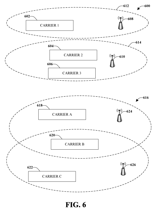
[0051] Fig. 6 is a schematic illustration of different orthogonalization
schemes
in accordance with the disclosed aspects. It should be understood that there
could be
more or fewer carrier and/or base stations than those illustrated and
described with
reference to this figure.
[0052] A full orthogonalization scheme is illustrated at 600 having three
carriers, Carrier 1 (602), Carrier 2 (604) and Carrier 3 (606) and two APs,
APl (608)
and AP2 (610). APl (608) might use Carrier 1 (602), illustrated by dotted line
612 and
AP2 (610) might use Carrier 2 (604) and Carrier 3 (606), illustrated by dotted
line 614.
In this full orthogonalization scheme, APl (608) and AP2 (610) do not
interfere since
completely different carriers are utilized.
[0053] At 616, a partial orthogonalization scheme is illustrated. There are
three
carriers, Carrier A (618), Carrier B (620) and Carrier C (622) and two APs:
APl (624)
and AP2 (626). As illustrated Carrier A (618) and Carrier B (620) belong to
APl (624)
and Carrier B (620) and Carrier C (622) belong to AP2 (626). In this case, the
APs 624
and 626 do not interfere on Carrier A (618) and Carrier C (622) but they do
interfere on
Carrier B (620).
CA 02677712 2009-08-07
WO 2008/108854 PCT/US2007/068974
16
[0054] Another scheme (not illustrated) can be referred to as a soft gradation
scheme. For example, on Carrier 1, APl is allowed to transmit at full power.
On
Carrier 2, APl transmits at half power and AP2 transmits at half power. On
Carrier 3,
AP1 transmits at very low power and AP2 transmits at high power. It should be
understood that other power schemes or power reduction amounts can be
utilized. Thus,
partial orthogonalization can include reducing a power associated with at
least a subset
of carriers.
[0055] Fig. 7 illustrates an RTTP time slot pattern 700 that may be utilized
in
conjunction with one or more aspects presented herein. According the figure,
an RTTP
time slot 702 is provided every fifth time slot during a transmission, as well
as a
plurality of non-RTTP time slots 704. RTTP transmission protocols can be
employed to
assign predefined ways in which interfering transmissions may fully or
partially
orthogonalize their transmissions, and pre-defined time periods, such as RTTP
slots
702, when interfering transmissions may adhere to the predefined
orthogonalization
protocols. During non-RTTP time slots, transmissions may be performed without
any
restrictions. For purpose of illustration, consider a multi-carrier EVDO
system, wherein
all base stations are synchronized. An RTTP time slot 702 may be defined
within a
longer time period 700, and the base stations within an interfering region may
know the
location and periodicity of such RTTP slot 702. Furthermore, each base station
may be
assigned a subset of resources that they may utilize for the RTTP slot 702. It
will be
appreciated that while the length of some RTTP slots 702 may be substantially
similar
to non-RTTP slot 7041ength, other RTTP slots 702 may be longer or shorter than
non-
RTTP slots 704, depending on design parameters, interference requirements, and
the
like. According to another aspect, RTTP slots may have a uniform length
relative to
each other, which may be longer than, shorter than, or substantially similar
to non-
RTTP slots.
[0056] Fig. 8 is an illustration of four APs within an interfering region 800
and
carrier assignments 802 for each AP to use during an RTTP slot, in accordance
with one
or more aspects. During non-RTTP slots, each AP may be permitted to use all 8
carriers. Thus, during RTTP slots, complete orthogonality to the main
interferers may
be obtained, while in other slots (e.g., non-RTTP slots) universal frequency
reuse may
be optimized. As will be understood by those skilled in the art, the processes
associated
CA 02677712 2009-08-07
WO 2008/108854 PCT/US2007/068974
17
with determining which base stations are within an interfering set and how
they are
informed of the RTTP can be performed, for instance, when the network topology
changes, and may utilize feedback from receivers in a region of a wireless
communication environment. Thus, RTTP time slots may be used for any
transmissions
that may benefit from increased robustness. For example, control channel
transmission
that needs to reach the edge of a cell, low-rate delay-sensitive transmissions
to a
receiver, transmissions that are close to reaching their HARQ retransmission
limit, and
the like are types of transmissions that may benefit from the various aspects
described
herein.
[0057] Fig. 9 is an illustration of an access termina1900 that facilitates
providing a predefined protocol for fully or partially orthogonalizing
interfering
transmissions, in accordance with one or more aspects. Access termina1900
comprises
a receiver 902 that receives a signal from, for instance, a receive antenna
(not shown),
and performs typical actions thereon (e.g., filters, amplifies, downconverts,
etc.) the
received signal and digitizes the conditioned signal to obtain samples. The
received
signal can include a reverse link interference indicator thereon. Receiver 902
can also
receive an orthogonalization protocol (e.g., full, partial). Receiver 902 can
comprise a
demodulator 904 that can demodulate received symbols and provide them to a
processor
906 for channel estimation. Processor 906 can be a processor dedicated to
analyzing
information received by receiver 902 and/or generating information for
transmission by
a transmitter 916, a processor that controls one or more components of access
terminal
900, and/or a processor that both analyzes information received by receiver
902,
generates information for transmission by transmitter 916, and controls one or
more
components of access termina1900. Additionally, processor 906 may execute
instructions for evaluating performing a resource reuse protocol during non-
RTTP slots,
for performing a partial or complete orthogonalization protocol during RTTP
slots, for
determining a level of orthogonalization (e.g., complete, partial, none, etc.)
[0058] Access termina1900 can additionally comprise memory 908 that is
operatively coupled to processor 906 and that may store data to be
transmitted, received
data, and the like. Memory 908 may store information related to link quality
values
(e.g., DRC, CQI), reverse link interference indicator (e.g., RAB) values
and/or signal
strength, protocols for evaluating the foregoing, protocols for comparing
evaluated
CA 02677712 2009-08-07
WO 2008/108854 PCT/US2007/068974
18
values to predetermined threshold values in order to facilitate determining an
appropriate action (e.g., complete or partial orthogonalization), etc.
[0059] It will be appreciated that the data store (e.g., memory 908) described
herein can be either volatile memory or nonvolatile memory, or can include
both
volatile and nonvolatile memory. By way of illustration, and not limitation,
nonvolatile
memory can include read only memory (ROM), programmable ROM (PROM),
electrically programmable ROM (EPROM), electrically erasable PROM (EEPROM), or
flash memory. Volatile memory can include random access memory (RAM), which
acts as external cache memory. By way of illustration and not limitation, RAM
is
available in many forms such as synchronous RAM (SRAM), dynamic RAM (DRAM),
synchronous DRAM (SDRAM), double data rate SDRAM (DDR SDRAM), enhanced
SDRAM (ESDRAM), Synchlink DRAM (SLDRAM), and direct Rambus RAM
(DRRAM). The memory 908 of the subject systems and methods is intended to
comprise, without being limited to, these and any other suitable types of
memory.
[0060] Receiver 902 is further operatively coupled to signal generator 910,
which may generate DRC, CQI or other information for transmission to an access
point,
which may then compare the received value(s) to a number of predetermined
thresholds
to determine a level of orthogonalization to apply to subsequent forward link
transmissions to reduce interference, as described above. Signal generator 910
can be
configured to execute a robust transmission protocol during one or more RTTP
slots.
These RTTP slots can be defined by the robust transmission protocol as
potential
candidates during which the orthogonalization protocol could be executed.
Additionally, signal generator 910 can activate one or more RTTP slots for use
associated with a reverse link transmission based on a reverse link
interference
indicator.
[0061] An indicator evaluator 912 may evaluate and/or monitor a received
signal to determine whether an reverse link interference indicator (e.g., RAB)
is set,
whether the signal is decodable, etc., in order to facilitate determining
whether to
employ a designated subset of available carriers for a subsequent transmission
or
whether to relinquish control there over, as described above. Indicator
evaluator 912
may determine whether the reverse link interference indicator is set in a
received signal
and the signal generator 910, based on the determination, may activate one or
more
CA 02677712 2009-08-07
WO 2008/108854 PCT/US2007/068974
19
RTTP slots for transmission on a reverse link. The indicator evaluator 912 may
further
evaluate a signal strength at which the reverse link interference indicator is
received and
the signal generator 910, can use the evaluated signal strength to determine
activation of
RTTP. The signal generator 910 can adjust a level of orthogonality for a
reverse link
transmission as a function of the signal strength of the reverse link
interference
indicator. Additionally, the signal generator 910 may continue to employ the
designated
subset of carriers for the reverse link transmission if the reverse link
interference
indicator is set by at least one AP that is not serving this access
termina1900. When the
indicator evaluator 912 determines that a reverse link interference indicator
is no longer
set, such as through monitoring of the received signal, the signal generator
910 can
deactivate the use of RTTP resources on all carriers in an unrestricted
manner.
[0062] Access termina1900 still further comprises a modulator 914 and a
transmitter 916 that transmits the signal to, for instance, a base station, an
access point,
another access terminal, a remote agent, etc. Although depicted as being
separate from
the processor 906, it is to be appreciated that signal generator 910 and
indicator
evaluator 912 may be part of processor 906 or a number of processors (not
shown).
[0063] Fig. 10 is an illustration of a system 1000 that facilitates permitting
partial orthogonalization of transmissions when interference is high and
resource reuse
at other times, in accordance with one or more aspects. System 1000 comprises
an
access point 1002 with a receiver 1010 that receives signal(s) from one or
more user
devices 1004 through a plurality of receive antennas 1006, and a transmitter
1024 that
transmits to the one or more user devices 1004 through a transmit antenna
1008.
Receiver 1010 can receive information from receive antennas 1006 and is
operatively
associated with a demodulator 1012 that demodulates received information.
Demodulated symbols are analyzed by a processor 1014 that can be similar to
the
processor described above with regard to Fig. 9, and which is coupled to a
memory
1016 that stores information related to resource reuse, resource assignments,
RTTP
slots, orthogonalization protocols, and/or any other suitable information
related to
performing the various actions and functions set forth herein.
[0064] Processor 1014 may be further coupled to signal evaluator 1018 and a
signal generator 1020, which may evaluate and generate respective signals for
access
point 1002. Signal evaluator 1018 may compare a received signal (e.g., DRC
signal) to
CA 02677712 2009-08-07
WO 2008/108854 PCT/US2007/068974
a plurality of thresholds to determine whether to completely or partially
orthogonalize
subsequent transmissions to mitigate interference. Signal evaluator 1018
define RTTP
resources, such as by determining how often control data is to be sent and/or
based on
interference data. In accordance with some aspects, the RTTP resources are
defined
offline. The RTTP resources can identify a location of at least one RTTP slot.
In
addition, the RTTP resources can include a set of one or more carriers to be
executed
during the one or more RTTP slots. For example, a partial orthogonalization
protocol
may be executed during one or more RTTP slots if a forward link quality
information
value is below a first predetermined threshold and higher than a second
predetermined
threshold. Partial orthogonalization may include reducing a power associated
with at
least one carrier. A complete orthogonalization protocol may be executing
during one
or more RTTP slots when information indicates that a forward link quality
value is
below the second predetermine threshold. Signal evaluator 1018 may execute a
universal frequency reuse during non-RTTP slots. A universal frequency reuse
protocol
may be executed during one or more RTTP slots if information about a forward
link
quality value is not decoded or is decoded but has a value below a first
predetermined
threshold.
[0065] Signal generator 1020 may generate and/or set a reverse link
interference
indicator (e.g., reverse activity bit) in a forward link signal to permit an
access terminal
to evaluate the interference indicator in order to determine whether to employ
a pre-
designated set of carriers for transmission on a reverse link during RTTP
slots. Signal
generator 1020 may identify interfering transmissions and then assign RTTP
resources
to base stations in an interfering region and signal evaluator 1018 may
execute an
orthogonalization protocol during one or more RTTP slots to provide
orthogonalization.
The RTTP slots can be specified for use during which the orthogonalization
protocol
may be executed. For example, if additional robustness is desired, a fraction
or ratio of
RTTP slots to non-RTTP can be changed or modified. A slot size can be
adaptively
changed and once a slot size is defined, the slot size for both RTTP and non-
RTTP slots
are the same.
[0066] Signal evaluator 1018 may evaluate a channel quality feedback signal
from a receiver that it causes interference to. Signal generator 1020 can
increase RTTP
slot duration and/or increase the fraction of RTTP slots as perceived
interference
CA 02677712 2009-08-07
WO 2008/108854 PCT/US2007/068974
21
increases. A multitude of RTTP slots can be inserted into a transmission
schedule at
defined intervals, which can be regular or random intervals. As interference
increases,
the interval between RTTP slots may be decreased.
[0067] Processor 1014 may execute instructions for assigning resources to user
devices 1004, for generating and/or defining RTTP slots, allocating RTTP
resources,
defining orthogonalization protocols, etc. Processor 1014 may be further
coupled to a
modulator 1022, which may multiplex assignment information for transmission by
a
transmitter 1024 through antenna 1008 to user device(s) 1004. Although
depicted as
being separate from processor 1014, it is to be appreciated that signal
evaluator 1018,
RAB generator 1020, and/or modulator 1022 may be part of processor 1014 or a
number of processors (not shown).
[0068] Fig. 11 shows an exemplary wireless communication system 1100. The
wireless communication system 1100 depicts one base station and one terminal
for sake
of brevity. However, it is to be appreciated that the system can include more
than one
base station and/or more than one terminal, wherein additional base stations
and/or
terminals can be substantially similar or different for the exemplary base
station and
terminal described below. In addition, it is to be appreciated that the base
station and/or
the terminal can employ the systems and/or methods described herein to
facilitate
wireless communication there between.
[0069] Referring now to Fig. 11, on a downlink, at access point 1105, a
transmit
(TX) data processor 1110 receives, formats, codes, interleaves, and modulates
(or
symbol maps) traffic data and provides modulation symbols ("data symbols"). A
symbol modulator 1115 receives and processes the data symbols and pilot
symbols and
provides a stream of symbols. A symbol modulator 1120 multiplexes data and
pilot
symbols and provides them to a transmitter unit (TMTR) 1120. Each transmit
symbol
may be a data symbol, a pilot symbol, or a signal value of zero. The pilot
symbols may
be sent continuously in each symbol period. The pilot symbols can be frequency
division multiplexed (FDM), orthogonal frequency division multiplexed (OFDM),
time
division multiplexed (TDM), frequency division multiplexed (FDM), or code
division
multiplexed (CDM).
[0070] TMTR 1120 receives and converts the stream of symbols into one or
more analog signals and further conditions (e.g., amplifies, filters, and
frequency
CA 02677712 2009-08-07
WO 2008/108854 PCT/US2007/068974
22
upconverts) the analog signals to generate a downlink signal suitable for
transmission
over the wireless channel. The downlink signal is then transmitted through an
antenna
1125 to the terminals. At terminal 1130, an antenna 1135 receives the downlink
signal
and provides a received signal to a receiver unit (RCVR) 1140. Receiver unit
1140
conditions (e.g., filters, amplifies, and frequency downconverts) the received
signal and
digitizes the conditioned signal to obtain samples. A symbol demodulator 1145
demodulates and provides received pilot symbols to a processor 1150 for
channel
estimation. Symbol demodulator 1145 further receives a frequency response
estimate
for the downlink from processor 1150, performs data demodulation on the
received data
symbols to obtain data symbol estimates (which are estimates of the
transmitted data
symbols), and provides the data symbol estimates to an RX data processor 1155,
which
demodulates (i.e., symbol demaps), deinterleaves, and decodes the data symbol
estimates to recover the transmitted traffic data. The processing by symbol
demodulator
1145 and RX data processor 1155 is complementary to the processing by symbol
modulator 1115 and TX data processor 1110, respectively, at access point 1105.
[0071] On the uplink, a TX data processor 1160 processes traffic data and
provides data symbols. A symbol modulator 1165 receives and multiplexes the
data
symbols with pilot symbols, performs modulation, and provides a stream of
symbols. A
transmitter unit 1170 then receives and processes the stream of symbols to
generate an
uplink signal, which is transmitted by the antenna 1135 to the access point
1105.
[0072] At access point 1105, the uplink signal from terminal 1130 is received
by
the antenna 1125 and processed by a receiver unit 1175 to obtain samples. A
symbol
demodulator 1180 then processes the samples and provides received pilot
symbols and
data symbol estimates for the uplink. An RX data processor 1185 processes the
data
symbol estimates to recover the traffic data transmitted by terminal 1130. A
processor
1190 performs channel estimation for each active terminal transmitting on the
uplink.
Multiple terminals may transmit pilot concurrently on the uplink on their
respective
assigned sets of pilot subbands, where the pilot subband sets may be
interlaced.
[0073] Processors 1190 and 1150 direct (e.g., control, coordinate, manage,
etc.)
operation at access point 1105 and terminal 1130, respectively. Respective
processors
1190 and 1150 can be associated with memory units (not shown) that store
program
CA 02677712 2009-08-07
WO 2008/108854 PCT/US2007/068974
23
codes and data. Processors 1190 and 1150 can also perform computations to
derive
frequency and impulse response estimates for the uplink and downlink,
respectively.
[0074] For a multiple-access system (e.g., FDMA, OFDMA, CDMA, TDMA,
etc.), multiple terminals can transmit concurrently on the uplink. For such a
system, the
pilot subbands may be shared among different terminals. The channel estimation
techniques may be used in cases where the pilot subbands for each terminal
span the
entire operating band (possibly except for the band edges). Such a pilot
subband
structure would be desirable to obtain frequency diversity for each terminal.
The
techniques described herein may be implemented by various means. For example,
these
techniques may be implemented in hardware, software, or a combination thereof.
For a
hardware implementation, which may be digital, analog, or both digital and
analog, the
processing units used for channel estimation may be implemented within one or
more
application specific integrated circuits (ASICs), digital signal processors
(DSPs), digital
signal processing devices (DSPDs), programmable logic devices (PLDs), field
programmable gate arrays (FPGAs), processors, controllers, micro-controllers,
microprocessors, other electronic units designed to perform the functions
described
herein, or a combination thereof. With software, implementation can be through
modules (e.g., procedures, functions, and so on) that perform the functions
described
herein. The software codes may be stored in memory unit and executed by the
processors 1190 and 1150.
[0075] Fig. 12 is an illustration of an apparatus 1200 that facilitates using
a
robust transmission protocol to trade off between system capacity and
interference
robustness on a forward link, in accordance with one or more aspects.
Apparatus 1200
is represented as a series of interrelated functional blocks, which can
represent functions
implemented by a processor, software, or combination thereof (e.g., firmware).
For
example, apparatus 1200 may provide modules for performing various acts, such
as are
described above. Apparatus 1200 can facilitate identifying interfering
transmissions
and pre-defining a manner and time in which interfering transmissions may
orthogonalize (e.g., fully or partially) in order to mitigate interference. In
this manner,
resource reuse may be scaled to interference conditions, and reuse slots may
be applied
to services and/or transmissions that require robustness without effecting
transmission
efficiency in other time slots. By increasing interference robustness,
apparatus 1200
CA 02677712 2009-08-07
WO 2008/108854 PCT/US2007/068974
24
may permit cellular technologies, such as "EVDO-like" technologies, to be
deployed in
an ad hoc or unplanned/semi-planned manner.
[0076] Apparatus 1200 comprises a module for defining RTTP resources (e.g.,
frequencies, subcarriers, ...) 1202 that may allocate RTTP resources to base
stations
(e.g., access points or the like) in an interfering region. The RTTP resources
may be a
subset of resources used during other time slots and can identify a location
of at least
one RTTP slot. The RTTP resources can include a set of at least one carrier to
be
executed during at least one of the RTTP slots. A module for executing an
orthogonalization protocol 1204 may be employed to orthogonalize transmissions
from
base stations identified as main interferers in the interfering region during
an RTTP time
slot. Module for executing an orthogonalization protocol 1204 may facilitate
providing
partial orthogonality or complete orthogonality between transmissions as
described
above. In this manner, apparatus 1200 facilitates providing a flexible
interference
avoidance and reuse strategy, such as that described above with regard to
preceding
figures, to facilitate taking advantage of the benefits of the ad hoc or
unplanned/semi-
planned deployment.
[0077] Fig. 13 illustrates an apparatus that facilitates using a robust
transmission
protocol to trade off between system capacity and interference robustness on a
reverse
link, in accordance with one or more aspects. Apparatus 1300 is represented as
a series
of interrelated functional blocks, which can represent functions implemented
by a
processor, software, or combination thereof (e.g., firmware). For example,
apparatus
1300 may provide modules for performing various acts, such as are described
above.
Apparatus 1300 may comprise a module for receiving 1302 that receives an
orthogonalization protocol. Apparatus 1300 can also include a module for
executing
1304 the robust transmission protocol during one or more RTTP slots. The RTTP
slots
can be defined by the robust transmission protocol as potential candidates
during which
the orthogonalization protocol could be used
[0078] Apparatus 1300 can further include a module a module for receiving a
signal (nor shown) from, for instance, an access point and determines whether
a reverse
link interference indicator is set in the received signal. For example, the
module for
receiving a signal may detect the indicator and determine whether it is set
and
decodable. The determination of whether the indicator is decodable may
comprise, for
CA 02677712 2009-08-07
WO 2008/108854 PCT/US2007/068974
instance, evaluating received signal strength of the indicator and comparing
the received
signal strength to a predetermined threshold value. If the received signal
strength is
below the predetermined threshold value, then the indicator may not be
decodable.
Apparatus 1300 may further comprise a module for activation (not shown), which
can
activate one or more RTTP slots for transmission on a reverse link based on
the whether
the indicator is set or not set. In this manner, scalable resource reuse may
be performed
on a reverse link, in addition to a forward link as described above.
[0079] For a software implementation, the techniques described herein may be
implemented with modules (e.g., procedures, functions, and so on) that perform
the
functions described herein. The software codes may be stored in memory units
and
executed by processors. The memory unit may be implemented within the
processor or
external to the processor, in which case it can be communicatively coupled to
the
processor via various means as is known in the art.
[0080] What has been described above includes examples of one or more
aspects. It is, of course, not possible to describe every conceivable
combination of
components or methodologies for purposes of describing the aforementioned
aspects,
but one of ordinary skill in the art may recognize that many further
combinations and
permutations of various aspects are possible. Accordingly, the described
aspects are
intended to embrace all such alterations, modifications and variations that
fall within the
scope of the appended claims. Furthermore, to the extent that the term
"includes" is
used in either the detailed description or the claims, such term is intended
to be
inclusive in a manner similar to the term "comprising" as "comprising" is
interpreted
when employed as a transitional word in a claim.