Note: Descriptions are shown in the official language in which they were submitted.
CA 02677898 2009-08-11
WO 2008/109070 PCT/US2008/002850
SPEED CONTROL FOR SMALL LOADER
BACKGROUND OF THE INVENTION
[0001] The present invention provides a speed control system that may be
used, for
example, in place of the speed control system disclosed in U. S. Patent
Application
Publication No. 2005/0011696, which was published on January 20, 2005, and
subsequently
issued on June 13, 2006 as U. S. Patent No. 7,059,434.
SUMMARY OF THE INVENTION
[0002] In one embodiment, the invention provides a vehicle comprising: an
engine; at
least one driven wheel rotating under the influence of the engine to move the
vehicle; a speed
control handle pivotable through a range of motion to control the rate of
rotation of the driven
wheel, the speed control handle including an engaging portion that moves along
a path in
response to pivoting of the speed control handle; a cam member having varying
thickness, a
stop portion of the cam member being the portion of the cam member in the path
of the
engaging portion of the speed control handle for a given position of the cam
member; a
frictional member creating sufficient frictional forces to resist movement of
the cam member
with respect to the rest of the vehicle during ordinary operation of the
vehicle; and a handle
manipulated by an operator of the vehicle to overcome the friction created by
the frictional
member and move the cam member into a desired position corresponding to a
desired
thickness of the stop portion. The engaging portion of the control handle may
abut against the
stop portion of the cam member to define an end of the range of motion of the
control handle
such that the range of motion is limited as a function of the thickness of the
stop portion.
[0003] In another embodiment, the invention provides a speed limit assembly
for a
vehicle having a support plate with first and second sides, and a speed
control handle
pivotable through a range of motion, the speed control handle having an
engaging portion.
The assembly comprises: a cam member having varying thickness, a portion of
the cam
member in the path of the engaging portion of the speed control handle being a
stop portion,
the cam member being movable to adjust the portion of the cam member acting as
the stop
portion; a frictional member coupled to the cam member and abutting against
the first side of
the support plate to create sufficient frictional forces to resist movement of
the cam member
with respect to the support plate during ordinary operation of the vehicle;
and a handle
manipulated by an operator of the vehicle to overcome the friction created by
the frictional
member and move the, cam member into a desired position corresponding to a
desired
thickness of the stop portion. The engaging portion of the control handle may
abut against the
= 1
CA 02677898 2009-08-11
WO 2008/109070 PCT/US2008/002850
stop portion of the cam member to define an end of the range of motion of the
control handle
such that the range of motion is limited as a function of the thickness of the
stop portion.
[0004] In another embodiment the invention provides a method for limiting
the range of
motion of a speed control handle. The method comprises the steps of: (a)
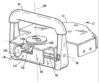
providing a cam
member having variable thickness; (b) defining a stop portion of the cam
member as the
portion of the cam member in the path of an abutment portion of the speed
control handle for
a given position of the cam member; (c) holding the cam member in a first
position with
frictional forces to maintain a first stop portion in the path of the abutment
portion, the first
stop portion having a first thickness; (d) defining a first end of the range
of motion of the
speed control handle upon contact of the abutment portion with the first stop
portion; (e)
overcoming the frictional forces through a handle to move the cam member into
a second
position corresponding to a second stop portion being in the path of the
abutment portion; and
(f) defining a second end of the range of motion of the speed control handle
upon contact of
the abutment portion with the second stop portion, the second end being
different from the
first end.
[0005] Other aspects of the invention will become apparent by consideration
of the
detailed description and accompanying drawings.
BRIEF DESCRIPTION OF THE DRAWINGS
[0006] Fig. 1 is a fragmentary rear perspective view of a typical loader
utilizing prior art
controls.
[0007] Fig. 2 is a top plan view of the loader of Fig. 1.
[0008] Fig. 3 is an enlarged rear perspective view of the control mounting
on the loader
of Fig. 1.
[0009] Fig. 4 is a cross sectional view taken along line 4-4 in Fig. 3.
[0010] Fig. 4A is a fragmentary sectional view taken along line 4A-4A in
Fig. 4.
[0011] Fig. 5 is a fragmentive perspective view of the control arrangement,
viewed in
opposite direction from Fig. 4 with the loader shown only fragmentarily and
with parts
omitted for sake of clarity.
[0012] Fig. 6 is a view similar to Fig. 5, showing an anti-reverse panel
that moves the
controls to a neutral position when engaging an object.
[0013] Fig. 7 is a rear perspective view of the control system as shown in
Fig. 5.
[0014] Fig. 8 is a schematic fragmentary view of the rear flange of the
control handle
support platform showing a prior art adjustment for changing the maximum
rearward
displacement of the control handle.
2
CA 02677898 2014-07-24
[0015] Fig. 9 is a fragmentary sectional view of a different prior art
form of a stop for limiting
rearward displacement of the control handle.
[0016] Fig. 10 is a perspective view of a control assembly for a vehicle
such as the loader
illustrated in Fig. 1, including a speed limiting control assembly embodying
the present invention.
[0017] Fig. 11 is an exploded view of the control assembly of Fig. 10.
[0018] Figs. 12A and 12B are cross-sectional views taken along section
line 12-12 in Fig. 10,
and illustrating the speed limiting control assembly in opposite extreme
settings.
DETAILED DESCRIPTION OF THE PREFERRED EMBODIMENTS
[0019] Before any embodiments of the invention are explained in detail,
it is to be understood
that the scope of the claims should not be limited by particular embodiments
set forth herein, but should
be construed in a manner consistent with the specification as a whole. The
invention is capable of being
other embodiments and of being practiced or of being carried out in various
ways. Also, it is to be
understood that the phraseology and terminology used herein is for the purpose
of description and should
not be regarded as limiting. The use of "including," "comprising," or "having"
and variations thereof
herein is meant to encompass the items listed thereafter and equivalents
thereof as well as additional
items. Unless specified or limited otherwise, the terms "mounted,"
"connected," "supported," and
"coupled" and variations thereof are used broadly and encompass both direct
and indirect mountings,
connections, supports, and couplings. Further, -connected" and -coupled" are
not restricted to physical or
mechanical connections or couplings.
[0020] The following description of Figs. 1-9 is taken in substance from
prior art U. S. Patent
Application Publication No. 2005/0011696, which was published on January 20,
2005, and subsequently
issued on June 13, 2006 as U. S. Patent No. 7,059,434.
[0021] Figs. 1 and 2 illustrate a small self-propelled walk-behind skid
steer loader 10. This type
of a loader is shown in U.S. Patent No. 6,832,659 for a loader frame and bolt-
on track drive. The loader or
other vehicle can have a ride on platform attached at the rear as shown in
U.S. Patent Application
Publication No. 2004/0145134 Al, published on July 29, 2004. The terms
"loader" and "vehicle" are
intended to include various self-propelled vehicle arrangements, and includes
vehicles that have steerable
wheels, as well as skid steer arrangements. The zero turn radius machines that
are common in lawn and
garden application can be controlled with the present invention and are
included in the term "vehicle."
3
CA 02677898 2009-08-11
WO 2008/109070 PCT/US2008/002850
[0022] The loader has a frame 12 that supports upright frame plates 14 and
16 on
opposite sides of the loader. The plates 14 and 16 are part of the frame 12
and are joined with
cross plates as needed, and can include lower cross plates that can form an
operator's platform
at the rear if desired.
[0023] The rear portions of the loader have side plates 20 that are spaced
from and
parallel to the frame plates 14 and 16. The spaces between the side plates 20,
and the
respective frame plates 14 and 16 are used for mounting a lift arm assembly
24. The lift arm
assembly 24 is pivotally mounted as at 26 to the frame 12 and positioned in a
desired
location. The lift arm assembly 24 has individual lift arms, as shown, and a
mast 28 is used
for mounting a bucket control or tilt cylinder 28A for a loader bucket, or for
other accessories
that may be mounted on an attachment plate 29 at the front end of the lift
arms.
[0024] The loader 10 has an internal combustion engine 30 mounted at an
engine housing
or compartment 30A that is used for driving a hydraulic pump 31 for the lift
and tilt actuators
60 and 28A acting through suitable valves 31A. Auxiliary actuators also can be
provided.
Also, the engine drives pumps 32A and 32B, which are a part of a swash plate
pump and
motor unit as conventionally used.
[0025] The pump and motor units form ground drive systems including a motor
and
motor controls, which drive system can be electric or other types of
controlled drive.
[0026] Hydraulic fluid under pressure from pumps 32A and 32B is provided to
unitarily
mounted motors 36A and 36B, respectively. The output of the pumps can be
varied for speed
control, and also reversed. The controls 34 include pump controls that are
mounted right at
the unitary pump and motor units. The pumps 32A and 32B are swash plate type
pumps that
are controllable to vary an output to in turn drive the associated motor in a
selected direction
of rotation, as well as varying the speed of the motor rotation. Movement of
the pump control
levers, which will be shown subsequently, determines the direction of rotation
and speed of
the associated motor. The motor speed and direction is thus controlled by the
position of the
controls 34.
[0027] The motors 36A and 36B are used for propelling the loader by
individually
driving drive sprockets 38, on the sides of the machine, to in turn drive
tracks 40A and 40B .
that are mounted on the sides of the loader. Tracks 40A and 40B are shown in
Fig. 2.
Wheeled loaders or vehicles would be driven with normal mechanical drive
trains to the
wheels, or can be operated with ground engaging wheels mounted right on motor
shafts.
4
CA 02677898 2009-08-11
WO 2008/109070 PCT/US2008/002850
[0028] The tracks mount over suitable idler rollers, including a rear idler
roller 42, as
shown in Fig. 1. The tracks are supported on the ground with bogie wheels 46
that hold the
lower reach or length 48 of the track in a suitable orientation.
[0029] The tension in the track is maintained with the slide 50 that mounts
rear idler
roller 42 and which is loaded with a spring 52 in a housing 54 attached to the
track support
frame on each side of the loader. A front idler roller is used for mounting
the front end of the
track.
[0030] Schematically shown is a hydraulic cylinder 60 that is typically
used for raising
and lowering lift arms, and which can be attached to the loader frame at the
lower end shown
at 62, and attached to the lift arms at a pivot on a bracket 64.
[0031] The control system that is shown generally at 34 (Fig. 4) is a drive
and steering
control assembly using a single control handle, so that an operator can steer
and control speed
and direction of movement of the loader with one hand, if desired, in a
convenient manner.
The controls are shown in more detail in Figs. 2-8. It should be noted that a
lever 66 can be
provided for controlling the lift arm cylinder 60, and the valves for
controlling other cylinders
can be controlled as desired. A throttle 68 is provided for controlling the
engine speed of
engine 30.
[0032] The controls 34 form an assembly supported relative to a control
panel 70. The
controls include a swinging or movable control handle support plate or
platform 72. As
shown in Fig. 5, for example, the side plate 14 of the loader has a main
mounting bracket 74
supported thereon. The main mounting bracket 74 has a lower mounting flange 76
that
extends laterally from the side plate 14. A vertical shaft 78 has a lower end
supported on the
flange 76. The shaft 78 extends upwardly and can be rotatably supported at the
upper end in a
suitable manner, relative to the side plate 14 or with a bracket to panel 70,
which is fixed to
the side plates. The shaft 78 is positioned at a desired location to position
and mount the
control support plate 72 in its proper location. The shaft 78 does not move
relative to the
frame except to rotate, and does not have to be vertical. It can incline
somewhat for
convenience.
[0033] The shaft 78 forms a main mounting support for the control assembly
34, and as
can be seen in Figs. 4-7, a sleeve or hub 80 is rotatably mounted on the shaft
78. The sleeve
80 is located in position axially along the shaft 78 with bearings held in
place in a suitable
manner, for example, with snap ring assemblies indicated at 81. The sleeve 80
is free to rotate
about the axis 82 of the shaft 78. A hub 84 at the upper end of sleeve 80 has
threaded bores
CA 02677898 2009-08-11
WO 2008/109070 PCT/US2008/002850
receiving cap screws 81 for holding a support block 86 that mounts the control
support plate
72, using suitable fasteners.
[0034] The control support plate 72 is securely fixed relative to the
sleeve 80, so it will
rotate about the axis 82 with the sleeve. The control support plate 72 extends
rearwardly from
axis 82 and has a control handle mounting section 88. The control handle
mounting section
88 has side arms 90 fixed thereto and the side arms 90 in turn mount a fixed
four sided
reference bar or hand rest 92 that defines a center space and surrounds a
movable control
handle 94 located in the center space. The control handle 94 is pivotally
mounted on a pivot
shaft 96 to the handle mounting section 88 of the control support plate 72.
The pivot shaft 96
is at the rear of the control support plate 72 and behind axis 80. The handle
94 will pivot
about a generally horizontal axis 98 of shaft 96, which is transverse to and
preferably
perpendicular to axis 82. Handle 94 also can be moved about the axis 82 of
upright shaft 78
from side to side, to cause the sleeve 80 to rotate as well.
[0035] The sleeve 80 has a pair of ears 100 that extend laterally from the
sleeve near the
lower end. A pivoting channel shaped bracket 102 is mounted on the ears 100
with suitable
pivot pins 104 so that channel bracket 102 will pivot about a generally
horizontal axis 106 of
pins 104, that is parallel to the pivotal axis 98 of the control handle 94.
The channel shaped
bracket 102 extends downwardly from the pivot pins 104 and axis 106. The side
walls 108A
and 108B of channel shaped bracket 102 extend rearwardly from pivot pins 104
so that a base
or cross wall 108C that joins wall 108A and 108B is spaced from sleeve 80.
[0036] The extent of the differential motion between the drives on the
opposite sides of
the vehicle is preferably limited with cooperating stops. The support block 86
is supported on
washer plates 83A and 83B separated by spacers 85A, 85B and 85C which pass
through slots
87A-87C in the fixed control panel 70. As shown in Fig. 4A, the slots 87A and
87B are
shaped and of length to provide steering speed stop surfaces when the support
plate is pivoted
about axis 82 of shaft 78. The steering motion is indicated by arrow 82A in
Fig. 4A. The
front slot 87C is longer and does not form a stop surface. The spacers 85A and
85B will
contact one end surface of the respective slots 87A and 87B for the stopped
positions.
[0037] Movement of the bracket 102 about the pivot pins 104 and thus the
axis 106 is
controlled by the control handle 94 pivoting about the parallel axis 98. The
control handle 94
has a forwardly extending arm or lever 110 that is moved by the handle. A
first end of a link
112 is connected to the arm 110. The link 112 also has a second end connected
as at 114 to
the upper portion of cross wall 108C of the bracket 102. Thus, when the handle
94 is pivoted,
the arm 110 will move up and down, and will cause the bracket 102 to pivot
about the axis
6
CA 02677898 2009-08-11
WO 2008/109070 PCT/US2008/002850
106. This will then cause the lower ends of the side walls 108A and 108B to
move in an arc
extending in fore and aft directions relative to the frame of the loader. This
movement
provides direction and speed control inputs to the drive system.
[0038] Movement of the lower corners of the side walls 108A and 108B is
used to control
the individual pump and motor units. In order to do this, a first link 116A
and a second link
116B are connected at pivots 118A and 118B to the lower corners of the walls
108A and
108B, respectively. These links 116A and 116B in turn extend downwardly and
are
connected to control levers 120A and 120B of the pumps 32A and 32B that in
turn control
the motors 36A and 36B. The levers 120A and 120B are control levers of the
purchased
pump/motor assembly for swash plate controlled motors and form drive system
control
levers. The motors 36A and 36B are suitably mounted to the loader frame, so
that the motors
are fixed in position.
[0039] The motors 36A and 36B in turn have drive sprockets on output shafts
that are
used for driving the respective tracks in a conventional manner. The pumps 32A
and 32B
have control shafts shown in section in Fig. 5 for example at 122A and 122B
that are part of a
conventional pump/motor assembly. The levers 120A and 120B are mounted on the
pump
control shafts, and when the levers 120A and 120B are moved, the shafts 122A
and 122B are
also rotated to adjust the position of the swash plates of the pumps. The
position adjustments
are built-in controls of the pumps 32A and 32B and thus, the motors 36A and
36B. Moving
the levers 120A and 120B from a centered position causes the motors to rotate
in a
corresponding direction and at a speed proportional to the displacement of the
levers 120A
and 120B from center.
[0040] The control levers 122A and 120B are spring loaded to be centered by
a separate
spring return lever arrangement for each of the pump and motor units. Plates
124A and 124B
are used for supporting the centering levers and springs. The plates 124A and
124B are
supported relative to the pump and motor units with suitable fasteners or the
plates can be
mounted directly to the loader frame, if desired. The plates 124A and 124B are
fixed and
each plate pivotally mounts a pair of spring loaded centering or return
levers. Levers 126A
and 126B are pivoted on plate 124A and levers 127A and 127B are pivotally
mounted on
plate 124B, for centering the pump control levers 120A and 120B of the
respective pump and
motor units, which centering action returns the pumps and thus the motors to a
stopped or
neutral position.
[0041] The levers 126A and 126B are pivoted onto the plate 124A at pivots
128 and
levers 127A and 127B are pivoted on plates 124B at pivots 129. A spring 130 is
connected
7
CA 02677898 2009-08-11
WO 2008/109070 PCT/US2008/002850
between pins 132 on levers 126A and 126B. A separate spring 131 is attached in
a suitable
manner onto pins 133 on levers 127A and 127B. The springs 130 and 131 each
provide a
spring load tending to urge the upper ends of the respective pairs of spring
centering levers
126A and 126B, and 127A and 127B together. This action will move the
respective pump
control lever 120A and 120B to a centered position.
[0042] The upper ends of the pair of spring centering levers 126A and 126B
bear against
the opposite edges of pump control lever 120A. The upper ends of the pair of
spring
centering levers 127A and 127B bear against the opposite edges of pump control
lever 120B.
[0043] The spring centering levers are stopped from moving together when
they reach the
centered position of the lever. For example, levers 126B and 127B engage stops
136A and
136B. The spring centering levers 126A and 127A engage stop pins 137A and 137B
that
protrude out from plates 124A and 124B to form a stop for these levers. The
stops prevent
movement of one lever toward the other lever of the pair beyond the positions
shown in Fig.
5. Thus, if the pump control lever 120A moves rearwardly from the position of
Fig. 5,
centering lever 126B would move rearwardly as well, and since centering lever
126A is
against stop pin 137A, the spring 130 would extend. As soon as the external
force (on lever
94) causing the lever 120A to move is relieved, the spring 130 would force
control lever
120B and control lever 120A back to the neutral position of Fig. 5. Spring 131
acts in the
same manner to center the levers 127A and 127B.
[0044] A spring return to a centered position for the motor control levers
120A and 120B
is provided in a similar manner in both directions of movement of the pump
control levers
which in turn control the drive motors. The motor control levers are in a
neutral or no-drive
position when centered.
[0045] A feature of having the spring centering or return to neutral
function right at the
pump and motor drive units is that if a control link becomes unfastened or
loose, the motor
will be stopped by the spring centering, right at the pump or motor control.
This same
centering of control levers or valves can be used for different forms of
drives.
[0046] Movement of the drive system or pump control levers 120A and 120B in
fore and
aft directions is caused by moving the control handle 94 about the axis 98, or
pivoting the
handle mounting portion 88 of the support plate 72 about the axis 82. Axis 82
is ahead of the
pivot shaft 96 and the control handle 94, so that the control handle 94 will
swing from side to
side when the support plate 72 is pivoted about the axis 82.
[0047] It can be seen, therefore, that if the control handle 94 and support
plate 72 are
swung to the right or left about the axis 82, there will be differential
movement in fore and aft
8
CA 02677898 2009-08-11
WO 2008/109070 PCT/US2008/002850
directions of the side walls 108A and 108B which provide steering inputs. In
other words, if
the movement was clockwise about the axis 82, as shown in Fig. 5, the side
wall 108B would
move rearwardly and the side wall 108A would move forwardly. This would cause
corresponding movement of links 116A and 116B and also the control levers 120A
and
120B. There would be a differential in the movement of direction of rotation
and drive speed
of the motors controlled by the respective control levers 120A and 120B. One
of the
centering levers for each pump control lever would be moved to stretch the
spring for that
pair of centering levers. When the control handle is moved back toward center
or is released,
the centering levers and springs return the pump control levers to center.
Movement of
control bracket 88 in a counter-clockwise direction about the axis 82 would
result in the
opposite movements of the walls 108A and 108B and the respective pump control
levers
120A and 120B, so that the motors would again operate in different directions
and this would
cause steering control for the vehicle driven by the motors.
[0048] If the vehicle being controlled has steerable wheels, the movement
about the
upright axis 82 can be used to operate a power steering valve for steering
ground engaging
wheels, and if such links are mounted to be pivoted about axis 106, the fore
and aft
movement of the lower ends of bracket 102 could have separated links used only
for fore and
aft movement and speed control. The steering and drive and speed control links
would thus
be separated.
[0049] Movement of the control handle 94 about the axis 98 with the control
plate 72
centered will cause the link 112 to move up or down. Assuming that the control
handle 94 is
moved forwardly or in a forward direction, the link 112 would move down
causing the
bracket 102 to pivot about the axis 106 so that the pivots 118A and 118B and
links 116A and
116B would move forwardly and simultaneous movement of the pump control levers
120A
and 120B in a forward direction would result. The centering levers 126A and
127A would
also move forwardly. The centering levers 126B and 127B are against stops 136A
and 136B,
so the springs 130 and 131 would be loaded.
[0050] Opposite movement of the control handle 94 would cause opposite
movement of
the pump control levers 120A and 120B through the movement of bracket 102 and
the links
116A and 116B.
[0051] When the control handle 94 is released, the springs 130 and 131
acting on the
spring centering of return levers will cause the pump control levers 120A and
120B to return
to the neutral position.
9
CA 02677898 2009-08-11
WO 2008/109070 PCT/US2008/002850
[0052] If desired, the amount of movement of the control handle 94 in a
reverse (or
forward) direction can be controlled so that the maximum speed of movement of
the loader in
a longitudinal direction can be limited. As shown, reverse speed is limited,
but forward speed
can be limited by stopping movement of the control handle 94 in an opposite
direction.
Adjustable stops for limiting speed in both directions of movement also can be
used. A
mechanical adjustment member is provided which engages the operating linkage
in a suitable
manner to provide a stop for limiting the amount of movement of the control
handle 94 when
moving the loader in the selected direction.
[0053] A rearward stop for speed control is shown schematically in Fig. 8,
wherein the
control support plate 72 is shown fragmentarily with a depending flange 89 at
the rear.
Additionally, the lever 110 is provided with a rearwardly extending bracket
having an
upwardly extending flange 111 that is positioned just inside the flange 89, as
can be seen in
Fig. 7.
[0054] Flange 89 is provided with a horizontal slot 135, and a threaded pin
136 is locked
in the slot. The pin can be adjusted along the length of the slot. The
protrusion of the pin 136
is illustrated in Fig. 4, where the pin end is shown to extend inwardly past
the upright
extending flange 111.
[0055] Lock nuts shown at 137 can be used for holding the 136 pin axially
in position,
and the pin thus can be adjusted manually so that the position of the pin 136
along the slot
135 can be changed.
[0056] The horizontal slot 135 aligns with an open triangular-shaped recess
138 that is
formed in the flange 111. The recess 138 has outwardly-extending, tapered
edges 138A and
138B that are shown in dotted lines and in solid lines in Fig. 8. The edges
extend from a
center peak. Only one tapered edge needs to be provided.
[0057] Since the flange 111 will move up and down as the handle 94 is
pivoted about the
axis 98 of the pin 96, the protrusion of the stop pin 136 will engage one of
the edges 138A or
138B, depending on the position of the pin, to stop movement of the handle
rearwardly, and
thus stop movement of the control levers for the pumps that regulate the speed
of the motors.
[0058] While the showing in Fig. 8 is schematic, it can be seen that the
triangular recess
138 can be open to the bottom, so that forward motion of the handle 94 which
will raise the
flange 111 is not restricted by the pin 136. Oppositely facing stop edges
would be used for
limiting forward speed.
CA 02677898 2009-08-11
WO 2008/109070 PCT/US2008/002850
[0059] The difference in the rearward speed can be adjusted, again, by
moving the
threaded stop pin 136, along the slot 135, and tightening it in position so
that one edge 138A
or 138B will engage the pin as the handle 94 is pivoted rearwardly to restrict
rearward speed.
[0060] Again, only one inclined edge, such as 138A, can be used as a sole
stop. The angle
of inclination of the edge relative to the long axis of slot 135 will provide
for the sensitivity
of the adjustment in speed as the pin 136 is moved along the slot 135.
[0061] The rearward speed limiting control also can be accomplished with a
wedge
shaped stop 113A on the front of a plate 113 which is slidably mounted on the
plate 72 for
lateral movement. The wedge 113A has a tapered lower edge that engages the
upper edge of
the arm 110. This is shown schematically from the front in Fig. 9. The plate
113 can be
retained laterally in position limiting movement of the upper edge of the
front end of arm 110
with a bolt or hand screw 113B at the rear (where the pin 136 is located). The
bolt 113B can
slide laterally in a slot 113C that is on a depending flange 113D of plate 113
for adjustment
of the rearward speed limiting position. The movement of the tapered lower
edge of wedge
113A is similar to movement of one of the edges 138A and 138B.
[0062] It also can be noted that if the motor speed is at a maximum speed
when the
control handle 94 is centered about axis 82 (for straight ahead vehicle
movement) and is all
the way forward, steering movement with the control handle 94 all the way
forward would be
difficult. In order to provide a controlled maximum speed and still have the
ability to change
the direction of movement of the loader by increasing the speed of one of the
drive motors
and decreasing the speed of the other, linkage stops are provided on the hub
or sleeve 80,
which will engage the aligned side portions of the back panel 108C of the
bracket 102.
[0063] As explained, the rotation of the support plate 72 is limited by the
ends of slots
87A-87B in panel 70 being engaged by the spacers 85A-85B. Thus, the forward
speed can be
maintained while the sharpness of the turn is limited.
[0064] Referring to Figs. 4 and 5, it can be seen that the sleeve 80 has a
pair of laterally-
extending ears on which threaded stop pins 140A and 140B are mounted. These
pins protrude
out to the rear of the sleeve 80, and are aligned with the back wall 108C of
the bracket 102. In
Fig. 4, the stop pin 140B is illustrated, and it can be seen that the end 141
of the stop pin
140B extends rearwardly of the sleeve 80. The end 141 of the pin will engage
the inner
surface of the rear wall 108C of the bracket 102, when the link 112 has been
pushed
downwardly so that the wall 108C pivots in toward the sleeve 80 in its lower
portions. When
the wall 108C engages the end portion 141 of either one of the stop pins 140A
and 140B, or
11
CA 02677898 2014-07-24
both, the position will result in the maximum straight ahead speed obtainable
with movement of the
handle 94 in a forward direction.
[0065] However, if the control levers 120A and 120B still are capable of
being moved forwardly
an additional selected amount, that means that the motors that are controlled
by these levers 120A and
120B also can be run faster than the maximum speed controlled by the stop pins
140A and 140B. Thus, if
forward movement of the handle 94 and thus the forward speed of the motor is
at the stop position against
the end portions 141 of the pins 140A and 140B, and the control support plate
72 is pivoted about the
axis 82, the link 116B, for example, can move forwardly even though the
bracket 102 cannot pivot about
the horizontal axis 106 of pins 104 to move the wall 108C forwardly. At the
same time, the link 116A
would be moved rearwardly, and differential drive speed for the tracks or
wheels is obtained for steering
control.
[0066] Swinging the control support plate 72 in an opposite direction
would cause the link 116A
to move forwardly, and since the lever 120A is not at its maximum speed
position, it can move forwardly
and the lever 120B can move rearwardly.
[0067] This provides for steering even when the pre-set maximum forward
speed is being
traveled in a straight line forward direction.
[0068] Additionally, a mechanical drive linkage disabling or
disengagement (stop) panel is
utilized at the rear of the loader. A reverse stop panel is disclosed in U. S.
Patent No. 6,902,016, issued
June 7, 2005. As shown, a panel 146 is pivotally mounted to the loader frame
plates 14 and 16, or, if
desired, to panel 70, about a horizontal axis 148 through suitable pins 150,
as shown in Fig. 6. The panel
146 has a downwardly extending section 152, and a forwardly extending section
154 with one or more
uprightly curved actuator fingers 156, at least one of which is in alignment
with the shaft 78, and thus in
alignment with the bracket 102. The mounting bracket 74 has a section 158
(Fig. 6) that supports a
pivoting member 160 for pivoting about a horizontal axis with pins 162.
[0069] The bracket 160 has a rearwardly extending portion 166, and a
downwardly extending
actuator 168 that aligns with the center finger 156 on the panel 146. When a
force such as that indicated
by the arrow 170 engages the panel 146 on the vertical section 152, the panel
146 will pivot about the
axis 148 in a direction that is toward the front of the loader and this will
cause the finger 156 to act on the
actuator 158 and in turn move the bracket 102 about its pivot so that the
motor levers will move toward
the front of the loader and will stop the rearward movement of the loader.
12
CA 02677898 2009-08-11
WO 2008/109070 PCT/US2008/002850
[0070] In this manner, the rearward movement of the loader can be
automatically stopped
if it engages an obstruction while it is moving rearwardly.
[0071] A panel like 146 also can be used at a forward end of a vehicle
frame to stop
forward drive if the vehicle engaged an, object at a forward end of the frame.
[0072] The hand controls are illustrated at a rear of a loader for operator
accessibility, but
if the vehicle has an operator seat, the control system can be placed ahead of
the operators
seat in the mid-portions or front portion of the vehicle.
[0073] The pump and motor units, or other motor controls can be positioned
to the rear of
the hand controls, and to the rear of an operator that may be seated on the
vehicle. The
control links would be positioned at pivots located to provide forward and
rearward
movement of the vehicle when the control handle is moved forward and rearward.
[0074] An alternate embodiment of a rear speed limiting mechanism is
illustrated in Figs.
10-12. In this alternate embodiment, the same reference numerals as used above
are used for
the same or substantially the same parts. In this embodiment, the handle 94 is
configured with
an overmold that includes a soft inner material for improved comfort and grip,
and a tough,
rugged outer layer that resists abrasion, oil, dirt, cold temps and
environmental degradation
such as exposure to sun and fading. By improving the operator's comfort and
grip on the
handle, the overmold permits the operator to work more hours without fatigue,
and
consequently improves the operator's productivity.
[0075] Fig. 10 illustrates the swinging or movable control handle support
plate or
platform 72 having top and bottom surfaces 72a, 72b (Figs. 12A and 12B). The
support plate
72 also includes the rear depending flange 89 as discussed above, and the
flange 89 includes
a slot 135 similar to that disclosed above. The slot has a first end 135a and
a second opposite
end 135b. Mounted to the support plate 72 and extending out of the slot 135 is
an operator
control or handle 240 (discussed below) of an alternate speed limiting control
assembly 210.
The handle 240 is movable between the first and second ends 135a, 135b of the
slot 135 and
positionable at either end 135a, 135b, or anywhere in between the ends 135a,
135b.
[0076] With reference to Fig. 11, the handle 94 includes a version of the
arm 110 that
includes a connection point 213 for the link 112. For the sake of this
invention, the arm 110 is
considered an engaging portion of the handle 94. The handle 94 is pivotable in
reverse and
forward directions, which correspond to counterclockwise and clockwise
rotation,
respectively, in Figs. 12A and 12B.
[0077] Referring again to Fig. 11, the speed limiting control assembly 210
includes a first
or main body 215, a second or capturing body 220, a friction washer or plate
225, a biasing
13
CA 02677898 2009-08-11
WO 2008/109070 PCT/US2008/002850
member 230 and a washer 235. The main body 215 includes the above-mentioned
handle
240, a mounting portion 245, and a cam member or portion 250. The main body
215 is
integrally formed as one piece, and may be formed, for example, by injection
molding a rigid
plastic material. The cam member 250 of the main body 215 is positioned
against the bottom
surface 72b of the support plate 72, and the handle 240 extends through the
slot 135. The
second body 220 includes a flange portion 255 and a spacer portion 260. The
spacer portion
260 extends through a hole 265 in the support plate 72, and has a lower
surface that sits on
the mounting portion 245 of the main body 215. The flange portion 255 is above
and spaced
apart from the support plate 72.
[0078] The friction washer 225 extends around the spacer portion 260 of the
capturing
body 220, and is sandwiched or captured between the top surface 72a of the
support plate 72
and the bottom surface of the flange portion 255. The friction washer 225 may
be made or
constructed, for example, of a composite material that creates a high friction
engagement
with both the support plate 72 and the flange portion 255 of the capturing
body 220.
Constructing the friction washer 225 of a composite material will also guard
against
corrosion and seizing, and will ensure that the washer 225 is will rotate once
the frictional
engagement between the washer 225 and the support plate 72 or flange 255 is
overcome.
[0079] The biasing member 230 may be, for example, a wave washer, a
Bellville washer,
or a split washer, and also extends around the spacer portion 260. The biasing
member 230 is
sandwiched or captured between the bottom surface 72b of the support plate 72
and the
washer 235, which sits on a top surface of the mounting portion 245 of the
main body 215.
[0080] A pair of fasteners 270, such as cap screws or bolts, extend through
holes 275 the
flange and spacer portions 255, 260 of the capturing body 220, and through
aligned holes 280
in the mounting portion 245 of the main body 215. The bottom ends of the
fasteners 270 are
secured via nuts or a threaded interconnection with the holes 280 in the
mounting portion
245. The fasteners 270 secure the first and second bodies 215, 220 for
rotation together. As
the fasteners 270 are tightened during assembly, the distance between the
flange 255 and
mounting portion 245 shrinks until the spacer 260 is securely held between the
caps of the
fasteners 270 and the mounting portion 245 of the main body 215.
[0081] When assembled, the biasing member 230 is compressed between the
bottom
surface 72b of the support plate 72 and the mounting portion 245 of the main
body 215. The
biasing member 230 applies a biasing force downwardly against the main body
215, away
from the support plate 72. This biasing force is transmitted up through the
fasteners 270 to
the capturing body 220, and downwardly biases the flange portion 255 against
the friction
14
CA 02677898 2009-08-11
WO 2008/109070 PCT/US2008/002850
washer 225. The flange portion 255 therefore applies a normal force that holds
the friction
washer 225 against the top surface 72a of the support plate 72. The normal
force gives rise to
a high friction engagement between the friction washer 225 and the flange
portion 255 and
top surface 72a of the support plate 72. The high friction engagement requires
high shear or
torquing forces to cause pivotal movement of the friction washer 225 with
respect to the
support plate 72. Such high shear or torquing forces are not created during
ordinary operation
of the vehicle 10 through, for example, vibrations.
[0082] In other constructions, the fasteners 270 may be flipped so that the
caps are
against the bottom surface of the main body 215 and the threaded ends thread
into holes 275
in the capturing body 220 or into nuts. Also in other embodiments, the
friction washer 225
may engage the bottom surface 72b of the support plate 72 and the biasing
member 230 may
engage the top surface 72a of the support plate 72.
[0083] The cam member 250 describes a curve or hook and has top and bottom
surfaces.
The thickness of the cam member 250 is defined in terms of the distance
between the top and
bottom surfaces. The thickness of the cam member 250 ramps or tapers from
being relatively
thick at the junction of the cam member 250 and mounting portion 245 to being
relatively
thin at the distal end 290 of the cam member 250. Whatever portion of the cam
member 250
in the path of the arm 110 as the handle 94 is pivoted may be called the stop
portion (i.e., the
thickness of the stop portion depends on the position of the cam member 250).
[0084] The speed limiting control assembly 210 is pivotable about a
vertical axis of
rotation 295 by virtue of the spacer portion 260 being positioned within the
hole 265 in the
support plate 72. The axis 295 is perpendicular to the axis 98 about which the
handle 94
pivots on the pivot shaft 96. As the assembly 210 pivots about the axis 295,
the thickness of
the stop portion of the cam member 250 is adjusted. The handle 240 is may be
moved from
the first end 135a of the slot 135 (which corresponds to the thickest portion
of the cam
member 250 being positioned between the arm 110 and the bottom of the support
plate 72) to
the second end 135b of the slot 135 (which corresponds to the distal end 290
(i.e., the thinnest
part) of the cam member 250 being positioned between the arm 110 and the
bottom of the
support plate 72).
[0085] The rearward range of motion of the handle 94 is dictated by the
position of the
speed limiting control assembly 210. In Figs. 12A and 12B, the handle 94 is
illustrated in a
neutral position in phantom. The handle 94 may be pivoted in the reverse
direction until the
arm 110 abuts against the stop portion of the cam member 250. The range of
motion of the
CA 02677898 2009-08-11
WO 2008/109070 PCT/US2008/002850
handle 94 is therefore inversely proportional to the thickness of the stop
portion (i.e., the
thicker the stop portion, the smaller the range of motion of the handle 94).
[0086] As illustrated in Fig. 12A, when the handle 240 is moved to the
first end 135a of
the slot 135, the stop portion is at its thickest. Because the bottom surface
72b of the support
plate 72 backs up the cam member 250, the bottom surface 72b may be termed an
abutment
surface. Positioning the thickest stop portion between the arm 110 and the
support plate 72
minimizes the rearward or reverse range of motion of the control handle 94,
and consequently
minimizes the reverse speed attainable by the vehicle. On the other hand, when
the handle
240 is pivoted to the second end 135b of the slot 135, as illustrated in Fig.
12B (in which the
handle 240 is pivoted out of the page and thus not in the section view), the
distal end 290 of
the cam member 250 is positioned between the arm 110 of the control handle 94
and the
bottom surface of the support plate 72 (i.e., the distal end 290 provides the
stop portion). In
other embodiments, the cam member 250 may be pivoted entirely out of the path
of the arm
110 when the handle 240 is at the second end 135b of the slot 135, such that
the control
handle 94 can pivot even further in the reverse direction until the arm 110
abuts the bottom
surface 72b of the support plate 72. This maximizes the rearward range of
motion of the
control handle 94, and consequently maximizes the reverse speed attainable by
the vehicle
10.
[0087] Thus, when the handle 240 is at the first end 135a of the slot 135,
reverse speed
attainable by the vehicle 10 is minimized. As the handle 240 is moved from the
first end 135a
to the second end 135b of the slot, the maximum reverse speed attainable by
the vehicle 10
increases until it is at a maximum when the handle reaches the second end
135b. The
illustrated cam member 250 has a substantially linear taper, so maximum
reverse speed
increases substantially linearly as a function of the distance the handle 240
is moved away
from the first end 135a. In other embodiments, the cam member 250 may have a
non-linear
profile and may include plateaus in which the thickness of the cam member 250
remains
substantially constant.
[0088] The handle 240 may be set to any position between the ends 135a,
135b of the slot
135 with a single motion by the operator of the vehicle. The frictional
engagement of the
friction washer 225 against both the flange portion 255 and the top surface
72a of the support
plate 72 resists movement of the speed limiting control assembly 210 under
normal operating
conditions of the vehicle. A side-to-side force applied to the handle 240 by
the operator,
however, is sufficient to overcome the frictional forces between the friction
washer 225 and
at least one of the flange portion 255 and the support plate 72. Once the
operator has the
16
CA 02677898 2009-08-11
WO 2008/109070 PCT/US2008/002850
speed limiting control assembly 210 in a desired position, the operator merely
releases the
handle 240, and the frictional forces maintain the assembly 210 in the desired
position.
Additionally, the biasing member 230 helps dampen vibratory forces that may
otherwise
overcome the frictional forces and cause the assembly 210 to drift out of the
desired position.
[0089] In other embodiments, the speed limiting control assembly 210 may be
modified
to adjust the range of motion of the handle 94 in the forward direction,
instead of or in
addition to the reverse direction.
[0090] Various features and advantages of the invention are set forth in
the following
claims.
17