Note: Descriptions are shown in the official language in which they were submitted.
CA 02678026 2009-08-12
= WO 2008/100379
PCT/1JS2008/001132
- 1 -
METHOD AND APPARATUS FOR MAKING A PAINT ROLLER
AND PRODUCT PRODUCED THEREBY
FIELD OF THE INVENTION
The present invention relates generally to paint rollers and methods of
manufacturing the same. More specifically, the present invention relates to an
improved paint roller and roller core, and method of and apparatus for making
such
roller and roller core, in which a reinforcing material is utilized.
BACKGROUND
Paint rollers, also known as paint roller covers, are widely used by both
amateurs and professionals to paint surfaces, such as walls and ceilings,
quickly and
economically, as well as with relative ease. Paint rollers are typically
comprised of a
tubular core and a paint absorbing cover or layer that is affixed to the core.
The
tubular core may be a solid structure, or the tubular core may be composed of
a
helically wound strip or strips of material that are bonded together. The
paint
absorbing cover may be made from a woven synthetic or natural fabric, or other
materials that are well known in the art.
Methods of helically winding strips of materials around a mandrel to form a
paint roller are well known. Such methods may allow paint rollers to be
manufactured in a continuous, assembly line fashion. Early paint rollers made
in this
manner used paperboard strips to form the core. In such well known processes,
multiple strips of paperboard are helically wound around a mandrel and are
bonded
together by an application of adhesive between the strips, which cures to form
a
core. A belt drive is placed on the formed core and is used to advance the
core down
the assembly line. A second application of adhesive is then applied to the
formed
core, after which a fabric cover is helically wound onto the formed core. A
cutter is
then used to cut the endless roller into sticks. The sticks are then cut to
size and
finished into usable paint rollers.
A disadvantage to paperboard core paint rollers is that paperboard is
exceedingly
soluble, especially in solvents. As a result, such cores would often times
delaminate
during use or cleaning.
In an attempt to solve the delaminating problem associated with ordinary
paperboard cores, phenolic impregnated paperboard strips were used in lieu of
ordinary
paperboard. However, even phenolic cores tend to delaminate after prolonged
exposure
to solvents. In addition, manufacturing processes utilizing phenolic
impregnated
CA 02678026 2009-08-12
WO 2008/100379 PCT/US2008/001132
- 2 -
paperboard strips were slow and required a long assembly line. The use of
phenolic
impregnated paperboard strips also created environmental issues.
Another attempt to solve the delaminating problem is disclosed in U.S. Pat.
No.
5,195,242 issued to Sekar ("the Sekar '242 Patent"). In the process described
in the
Sekar '242 Patent, Sekar disclosed helically winding multiple strips of
thermoplastic
material instead of paperboard or phenolic strips. It is well known that
thermoplastic
materials are resistant to paint solvents. In particular, multiple strips of
thermoplastic
material may be helically wound around a stationary mandrel and bonded
together using
preheated, liquid, thermoplastic to form a core. As with the paperboard and
phenolic
process, a belt drive is placed on the formed core for advancing the core down
the line.
A second application of liquid thermoplastic material is then applied to the
formed core
as an adhesive. A fabric cover is helically wound onto the formed core. A
cutter is then
utilized to cut the endless roller into sticks. The sticks are then cut to
size and finished
into usable paint rollers.
The process described in the Sekar '242 Patent has several drawbacks. Because
the manufacturing process involves the use of multiple strips of thermoplastic
material
and multiple points of application of liquefied thermoplastic, the process
would be
difficult to set up and operate. Additionally, such a process is expensive
because it
requires multiple nozzles for each strip of thermoplastic material. It has
also been
reported that cores formed of only thermoplastic material tend to be weaker
than cores
formed of other material, such as metal and cardboard strips; thus the useful
life of such
paint rollers is relatively short.
U.S. Pat, No. 5,468,207 issued to Bower ("the Bower '207 Patent") disclosed a
continuous paint roller manufacturing process using multiple thermoplastic
strips similar
to the process described in the Sekar '242 Patent, with the exception that
Bower
disclosed using direct heat, instead of liquefied thermoplastic, to bond the
thermoplastic
strips together to form a core. Bower also disclosed using direct heat, rather
than
liquefied thermoplastic, to bond the fabric cover to the formed core. The
process
disclosed in the Bower '207 Patent suffers from the same disadvantages as the
process
disclosed in the Sekar '242 Patent. In addition, the use of heaters to bond
the multiple
thermoplastic strips together and to bond the fabric cover to the formed core
is believed
to create additional difficulties in the determination of the amount of heat
to be applied
and the creation of even adhesive layers.
Another well known process that is in present commercial use resolved some of
the complexity problems associated with multiple thermoplastic strip
processes, such as
the processes disclosed in the Bower and Sekar Patents. In this process, which
appears
CA 02678026 2009-08-12
WO 2008/100379 PCT/US2008/001132
- 3 -
to be described in Canadian Pat. No. 2,170,722 also issued to Sekar ("the
Canadian '722
Patent"), a single strip of thermoplastic material is helically wound about a
mandrel,
instead of forming a core by helically winding multiple strips'. A single
application of
liquefied thermoplastic material is then applied to the wound strip.
Thereafter, a fabric
cover strip is helically wound directly over the liquefied thermoplastic and
wound strip.
A cutter is then utilized to cut the endless formed roller into individual
sticks. The
sticks are then cut to size and finished into usable paint rollers.
In contrast to certain well known multiple strip processes disclosed in the
prior
art, such as the Bower and Sekar processes discussed above, a belt drive in
the single
thermoplastic strip process could not be placed on the wound strip prior to
the
application of liquefied thermoplastic since there is no formed core prior to
the
application of the fabric cover. Instead, in the single thermoplastic strip
process, the
belt drive is placed on the fabric cover so the endless formed paint roller
can be
advanced down the assembly line.
However, the paint roller resulting from the single thermoplastic strip
process
described above is prone to certain defects. The ends of the wound strip of
such
rollers have a tendency to break apart, or unfurl, from the successive wind,
which
results in the end of the wound strip sticking out, consequently making the
roller
appear "out of round." This defect is due to the high tension memory of the
thermoplastic strip. In addition, paint rollers made from a single strip of
thermoplastic
are more susceptible to being crushed and may not have the desirable hardened
feel of
multiple layer or solid core paint rollers. In an effort to achieve the
hardened feel of a
multiple layer or solid core paint roller, thicker thermoplastic strips may be
used.
However, using thicker strips increases the potential for unfurling of the
wound strip
due to the higher tension memory of the thicker strip.
In view of the complexity of the methods of manufacturing multiple layer paint
rollers, such as the phenolic processes in Sekar '242 and Bower '207 discussed
above,
and further in view of the defects associated with the single strip process
described in
Sekar's Canadian '722 Patent, methods attempting to address one or more of
these
problems have been disclosed in subsequent patents .
One such method is disclosed in U.S. Pat. No. 6,159,134, also issued to Sekar
("the Sekar '134 Patent"). The Sekar '134 Patent discloses a method of
manufacturing
paint rollers comprising the steps of: helically advancing a first strip of
thermoplastic
material about a mandrel; helically advancing a second strip of thermoplastic
material
about the first strip of thermoplastic material in offset relation therewith;
helically
advancing a cover about the second strip; providing an adhesive between the
outer
CA 02678026 2014-08-12
- 4 -
surface of the first strip and the inner surface of the second strip;
providing an
adhesive between the outer surface of the outer strip and the inner surface of
the
cover; and forming a continuous laminated paint roller by applying a
compressive
force upon the cover. One disadvantage with this method is that it requires a
second strip of thermoplastic material and multiple applications of adhesive.
These
factors add to production cost and increase the size and complexity of the
assembly line. The second strip of thermoplastic material may also increase
packaging and bulk transportation costs due to the additional weight of the
second
strip.
It would therefore be desirable to provide a method for manufacturing a
robust, lightweight paint roller utilizing a single strip of base material in
the interest
of maximizing its structural integrity, decreasing its cost, and decreasing
its
shipping weight.
SUMMARY OF THE INVENTION
The foregoing drawbacks of paint rollers and paint roller manufacturing
processes are resolved to a large extent by a method and apparatus for
manufacturing a paint roller, and by products that are produced from the
method
and apparatus, all of which are in accordance with the invention, as will be
described herein in the form of exemplary embodiments.
In a first aspect of the invention, there is provided a reinforced core for a
paint roller comprising: a base layer comprising a single layer of material,
the base
layer formed from a solvent-resistant material; and a reinforcing layer
including a
mesh that is positioned over the base layer, the mesh comprising a plurality
of
fiberglass strands in a grid arrangement, the grid arrangement defining
openings
between adjacent strands, the strands having a nominal thickness that is
smaller
than the shortest dimension of the openings, resulting in large voids between
the
strands adapted to promote uniform application and distribution of an adhesive
through the mesh material and onto the base layer.
In a second aspect of the invention, there is provided a reinforced paint
roller comprising: a base layer comprising a single layer of material, the
base layer
CA 02678026 2014-08-12
- 5 -
formed from a solvent-resistant material; a reinforcing layer including a mesh
positioned over the base layer, the mesh comprising a plurality of fiberglass
strands
in a grid arrangement, the grid arrangement defining openings between adjacent
strands, the strands having a nominal thickness that is smaller than the
shortest
dimension of the openings, resulting in large voids between the strands
adapted to
promote uniform application and distribution of an adhesive through the mesh
and
onto the base layer; and a fabric cover positioned over the reinforcing layer.
In a third aspect of the invention, there is provided a method of assembling
a paint roller comprising the steps of: helically winding a base material
around a
mandrel; applying adhesive to an exposed portion of the base material;
helically
winding a reinforcing material around the base material, the reinforcing
material
including a mesh positioned over the base material, the mesh comprising a
plurality
of fiberglass strands in a grid arrangement, the grid arrangement defining
openings
between adjacent strands, the strands having a nominal thickness that is
smaller
than the shortest dimension of the openings, resulting in large voids between
the
strands adapted to promote uniform application and distribution of the
adhesive
through the mesh and onto the base material; applying the adhesive to an
exposed
portion of the reinforcing material; and helically winding a fabric cover over
the
reinforcing material.
In a fourth aspect of the invention, there is provided a method of
assembling a core of a paint roller comprising the steps of: helically winding
a base
material around a mandrel; applying an adhesive to an exposed portion of the
base
material; helically winding a reinforcing material around the base material,
the
reinforcing material including a mesh positioned over the base material, the
mesh
comprising a plurality of fiberglass strands in a grid arrangement, the grid
arrangement defining openings between adjacent strands, the strands having a
nominal thickness that is smaller than the shortest dimension of the openings,
resulting in large voids between the strands adapted to promote uniform
application and distribution of the adhesive through the mesh and onto the
base
material; and applying the adhesive to an exposed portion of the reinforcing
material.
CA 02678026 2014-08-12
- 5a -
BRIEF DESCRIPTION OF THE DRAWINGS
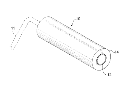
Fig. 1 is a perspective view of a paint roller made in accordance with one
embodiment of the present invention;
Fig. 2 is a cross-sectional view of the paint roller of Fig. 1; and
Fig. 3 is a diagrammatic representation of a side view of an apparatus for
assembling paint roller cores and paint rollers in accordance with one
embodiment of
the present invention.
Fig. 4 is a truncated perspective view of a core reinforcing layer material in
accordance with the present invention.
DETAILED DESCRIPTION
In Fig. 1, a paint roller 10 in accordance with one embodiment of the present
invention is shown. Paint roller 10 is of the type which is normally attached
to a roller
handle assembly 11, which is illustrated in phantom in Fig. 1. Paint roller 10
may be
constructed to operate successfully with a variety of roller handle
assemblies.
Paint roller 10 has a tubular core 12 comprised of a single inner layer, or
ply, of
helically wound base material. The helically wound base material is preferably
a
thermoplastic material, and more preferably polypropylene. Helically wound
about
the base material is a reinforcing material, which is attached to the base
material,
preferably by a suitable adhesive, such as liquid polypropylene. The
reinforcing
material may comprise a non-thermoplastic mesh material, such as a fiberglass
mesh,
for example. Attached to the outer surface of core 12, by the adhesive, is a
paint
applying fabric cover 14. The fabric cover 14 may be a conventional roller
cover fabric
that preferably has a heavy open weave backing made of a suitable
thermoplastic
material such as polyester woven into the fabric to allow for a superior
mechanical
bond between the fabric backing and base material. The fabric pile or nap may
be
composed of various materials or material blends, and be of different heights
depending on the particular application.
Fig. 2 is a cross-sectional view of paint roller 10 showing a portion of core
12
and cover 14 in greater detail. As illustrated in Fig. 2, core 12 has a single
inner
CA 02678026 2009-08-12
WO 2008/100379 PCT/US2008/001132
- 6 -
layer, or ply, of base material 16 and an outer reinforcing material 18. The
paint
roller of the present invention has significant advantages over conventional
paint
rollers. Among other benefits, paint roller 10 exhibits may of the desirable
properties
of paint rollers made with multiple layers of thermoplastic strips (e.g.,
hardened feel,
crush resistance, lower susceptibility to unfurling), while being less
expensive to
manufacture, lighter in weight, and less expensive to handle and ship.
Fig. 3 illustrates the method and shows the apparatus by which a paint roller
of
the present invention may be fabricated. The paint roller manufacturing
apparatus 20
includes a housing 22 to support a stationary mandrel 24 that is preferably
tapered. The
mandrel 24 may be cooled, preferably by an internal water chilling mechanism,
to
prevent the mandrel from overheating. As is well known, the diameter of the
mandrel
depends on the diameter of the paint roller desired. Generally, paint rollers
are made
with either 1.5-inch or 0.5-inch diameter cores. These diameter cores, as well
as any
other diameter core, can be made using this invention.
Paint roller manufacturing apparatus 20 includes a unique arrangement of
feeder
mechanisms and other components that produce an efficient and streamlined
process.
The relative position of the different components are particularly
advantageous for
reasons that will be better understood from the sections that follow. For
purposes of
description, the relative position of components may be described as being
"downstream" or "upstream" from one another. "Downstream" generally refers to
a
direction toward the end of the assembly line, and "upstream" generally refers
to the
direction toward the beginning of the assembly line.
The paint roller manufacturing apparatus 20 further includes a driving
apparatus,
preferably a belt drive, which advances the endless paint roller along the
mandrel. In
Fig. 3, apparatus 20 includes a belt drive 28 having two powered drums 28a and
28b
that are coupled to at least one drive belt 30. The drive belt 30 is
preferably placed at a
location immediately downstream of the location where a paint-applying fabric
cover 32
is wound onto the mandrel. In this arrangement, the belt drive 28 is provided
with
sufficient traction to advance the base material, reinforcement material, and
cover along
the mandrel. In addition, the downstream position of the belt drive 28 permits
the belt
drive to simultaneously serve as the drive mechanism, and as a final
compression
mechanism to securely press all the roller layers together.
A cutting device 34, which may be a "fly-away" cutter, cuts the endless paint
roller into useable segments, or "sticks". The sticks are then again cut to
the desired
length and finished into usable paint rollers.
CA 02678026 2009-08-12
WO 2008/100379 PCT/US2008/001132
- 7 -
The paint roller manufacturing apparatus 20 also includes one or more feeders
for
adding each of the component parts to the paint roller. The feeder mechanisms
may be
in the form of spindles, spools or other application means that allow for the
materials,
which typically are supplied in rolls, to be applied in a continuous fashion.
In Fig. 3, a
first feeder 50 continuously feeds base material 38, and a second feeder 52
continuously
feeds reinforcing material 40. A third feeder 54 continuously feeds fabric
cover 32. As
an alternative to continuous feeders, any of the materials may be applied by
hand.
The paint roller manufacturing apparatus 20 further includes an adhesive
application means. The adhesive application means may be in the form of a
single head
36, although multiple heads could be used. According to one exemplary
embodiment,
the head 36 distributes adhesive material, such as polypropylene. Head 36 is
coupled to
an adhesive extrusion device which includes a heater tube that receives a
supply of
polypropylene pellets that are melted within the heater tube and advanced with
the tube
by a screw-type mechanism to the head 36. Head 36 may be a die, where the
source of
the adhesive material is an extruder. Preferably, head 36 is placed in close
proximity to
the fabric cover 32.
In accordance with one process of the invention, the first step in making
continuous paint rollers using apparatus 20 is to helically wind a strip of
base material 38
about a longitudinal axis of a mandrel. The helically wound base material may
be a
thermoplastic material such as polypropylene. Polypropylene strips are
commercially
available and may be provided in the form of a roll. As is well known in the
art, a
lubricant such as 5% mineral oil may be applied to the inner surface of the
thermoplastic
strip prior to winding the strip onto the mandrel, in order to reduce friction
between the
wound strip and the mandrel as the wound strip advances along the mandrel.
A strip or layer of reinforcing material is helically wound about the wound
strip of
base material 38. A variety of materials may be used for the reinforcing
layer.
Preferably, the reinforcing layer is made from a thin light-weight non-
thermoplastic
material with a high tensile strength. In Fig. 3, the reinforcing layer is a
fiberglass mesh
40. Fiberglass reinforcing mesh 40 is preferably applied as a strip having the
same
width as the base material 38. In addition, mesh 40 is preferably provided in
roll
form, and has an open weave with relative large openings. Fiberglass
reinforcing
mesh 40 may be formed from any commercially available material, such as mesh
material manufactured by New York Wire Company, 152 North Main Street, Mount
Wolf, Pennsylvania, USA. Reinforcing mesh 40 may also be formed from other
synthetic or natural materials, including but not limited to nylon,
polyethylene,
rayon, polyacylonitrile, cellulose, hemp or sisal. The reinforcing mesh may
also be
formed from fine metal wire, such as screen material.
CA 02678026 2009-08-12
WO 2008/100379 PCT/US2008/001132
- 8 -
During assembly, an adhesive material 42, such as liquid polypropylene, is
applied from head 36. Adhesive material 42 may be applied in a layer, such as
a
single layer that is applied in such a manner so it will cover both the
exposed portion
of the strip of base material 38 and the exposed portion of reinforcing mesh
40.
More specifically, head 36 may be positioned along mandrel 24 at a location
downstream relative to the location where base material 38 is wound onto the
mandrel, and aligned more or less with the location where reinforcement layer
40 is
wound onto the mandrel. In this arrangement, a single application of adhesive
will
bond the adjacent turns of base material 38 with one another, and
simultaneously
bond the reinforcement layer 40 to the bonded turns of base material, all from
a
single stream or application of adhesive. The reinforcing material 40 will be
effectively embedded in the adhesive material 42, substantially eliminating
any
ridges or bumps in the finished product. A fabric cover 32 is helically wound
about
the adhesively embedded reinforcing material 40 and bonded to the wound strip
of
base material 38 and reinforcing material 40. Using this assembly process, a
reinforced, single-ply paint roller can be manufactured with only four feeder
mechanisms applying material onto the mandrel.
The orientation of base material 38, reinforcing material 40 and fabric cover
32
may vary from the orientations shown and described herein. Upon winding the
reinforcing material 40 onto the base material 38, for example, the edges of
the strip
of reinforcing material 40 may be offset from the edges of the strip of base
material
38. The reinforcing material 40 may be offset from the base material in
multiple
ways. For example, reinforcing material 40 may be wound onto the mandrel in an
angularly offset or transverse orientation relative to the base material 38,
forming a
criss-cross overlap. This criss-cross arrangement is illustrated in Fig. 3,
between
base material 38 and reinforcing material 40. Alternatively, reinforcing
material 40
may be wound onto the mandrel in a longitudinally offset position, but
parallel
orientation, relative to the turns of the base material 38, so that the center
of the
reinforcing mesh overlaps the joints of the wound strip of base material. This
type of
offset arrangement is illustrated in Fig. 3, between reinforcing material 40
and cover
material 32.
Prior to the hardening and setting of the layer of adhesive material 42, the
drive belt 30 may be used to apply pressure to the outer surface of the fabric
cover
32 and the component parts below, strengthening the bonds between the layers
of
material. In such an arrangement, belt drive 28 serves dual purposes of
advancing
the roller through the assembly line and pressing the layers together to form
a
CA 02678026 2009-08-12
WO 2008/100379 PCT/US2008/001132
- 9 -
tightly bound construction. A continuous paint roller 44 is formed about the
mandrel.
In an additional embodiment of the present invention, the reinforcing material
40
may be a solid strip of paperboard or metal reinforcing material to produce a
sufficiently
strong and lightweight core. As with the embodiments described above, the
fabric cover
32 could be wound in an orientation that is parallel to either to the
reinforcing material
40 or thermoplastic strip 38. The following are intended to be further non-
limiting
examples and illustrations of the invention.
1. A paint roller comprising;
a. an inner layer or ply of base material;
b. a reinforcing material; and
c. a fabric cover.
The layer or ply of base material of this embodiment may be formed from any
suitable material, such as a thermoplastic material (e.g., polypropylene). The
reinforcing
material of this embodiment may be formed from any suitable material, such as
a
fiberglass mesh. The fabric cover may formed from of any suitable material,
and is
preferably a fabric suitable for painting (or achieving some desired effect
with paint),
such as pile or nap with an open weave backing. The layer or ply of base
material,
reinforcing material and fabric cover are preferably bound together with an
adhesive, and
more preferably liquid polypropylene. Alternatively, the base material,
reinforcement
material and fabric cover may be heat bonded by applying heat to the
thermoplastic
base material. As noted above, heat bonding is less preferred because of the
difficulties
in setting optimum temperatures and avoiding uneven surfaces.
2. A method of making a paint roller comprising:
a. helically winding a layer or ply of base material around a mandrel;
b. applying an adhesive to the exposed portion of the base material;
c. helically winding a reinforcing material around the base material
and adhesive on the mandrel;
d. applying an adhesive to the exposed portion of the reinforcing
material;
e. helically winding a fabric cover over the base material, adhesive
and reinforcing material on the mandrel; and
CA 02678026 2009-08-12
\V 0 2(0)8/100379 PCT/US2008/001132
- 1 -
f. applying a compressive force upon the outer surface of
the fabric
cover thereby forming a continuous paint roller.
The layer or ply of base material of this embodiment may be made of any
suitable
material, such as a thermoplastic material (e.g., polypropylene). The
reinforcing
material of this embodiment may be made of any suitable material, such as
fiberglass
mesh. The fabric cover may be made of any suitable material, and is preferably
a fabric
suitable for painting (or achieving some desired effect with paint), such as
pile or nap
with an open weave backing. The layer or ply of base material, reinforcing
material and
fabric cover may be bound together with an adhesive, such as liquid
polypropylene. The
adhesive may be applied in a single layer that is applied in such a manner
from a single
die head so that the layer of adhesive covers both the exposed portion of the
base
material and the exposed portion of the reinforcing mesh. Prior to the
hardening and
setting of the adhesive, the drive belt is used to apply a compressive force
to the outer
surface of the fabric cover and the component parts below, thereby forming a
continuous
paint roller about the mandrel.
3. An apparatus for making paint rollers comprising:
a. a mandrel;
b. a driving apparatus that advances paint roller components along
the mandrel;
c. a base material application means;
d. a reinforcing material application means;
e. a fabric cover application means;
f. an adhesive application means that applies adhesive to the exposed
portion of the base material and the exposed reinforcing material to bind
the base material, reinforcing material and fabric cover together;
9. a compressing means that applies pressure upon the outer
surface
of the fabric cover thereby forming a continuous paint roller; and
h. a cutting means to cut the formed endless paint roller
into usable
lengths.
The layer or ply of base material of this embodiment may be made of any
suitable
material, such as a thermoplastic material (e.g., polypropylene). The
reinforcing
material of this embodiment may be formed from any suitable material, such as
fiberglass mesh. The fabric cover may be made of any suitable material, and is
preferably a fabric suitable for painting (or achieving some desired effect
with paint),
CA 02678026 2009-08-12
WO 2008/100379 PCT/US2008/001132
- 11 -
such as pile or nap with an open weave backing. The layer or ply of base
material,
reinforcing material and fabric cover may be bound together to form a paint
roller with
an adhesive, such as liquid polypropylene. Prior to the hardening and setting
of the
adhesive, the drive belt is used to apply a compressive force to the outer
surface of the
fabric cover and the component parts below, thereby forming a continuous paint
roller
about the mandrel. Because the drive belt is positioned over the fabric cover,
the drive
belt is accordingly positioned downstream of the fabric cover supply with
respect to the
longitudinal axis of the mandrel.
The reinforcing layer has been described in terms of a mesh material. The term
"mesh" may include a variety of materials including but not limited to porous
or
nonporous, and woven or non-woven fabrics, screens, sheaths, tapes, wires,
grids, solid
or perforated sheets, nets, lattice structures, powders and other materials,
with or
without laminates or coatings. Suitable reinforcing materials may include
synthetic,
metallic or other natural reinforcing materials. The reinforcing material may
be resistant
to solvents, or have other chemical properties that are desired for a specific
painting
application. Although the term "paint roller" has been used in this
specification, the
products and processes within the scope of the invention are not limited to
paint
applications per se, but may be used for any application in which a liquid is
applied to a
surface by a roller.
The single ply paint rollers of the present invention may be made to have the
strength of multiple ply paint rollers, but are more cost efficient to
manufacture and ship.
The resulting paint rollers of the present invention do not exhibit the
defects associated
with non-reinforced single strip paint rollers, such as bending and buckling.
Bending and
buckling are substantially eliminated by the reinforcement layer, which
provides an outer
skeleton over the base material. This outer skeleton provides the structural
integrity and
hoop strength needed to withstand internal stresses exerted by the base
material, and
external forces, while adding virtually no size or weight to the core
structure.
The reinforcing layer need not be a thick layer of material, and preferably
has a
nominal thickness of only a fraction the thickness of the base material. For
example, a
fiberglass mesh having a nominal thickness of less than 0.5 mm (0.197 in.) is
desirable
to provide a reinforcing layer that adds virtually no size or weight to the
finished core.
In a preferred embodiment, the mesh is made up mostly of relatively large
openings
separated from one another by relatively narrow wires, strands or the like. In
this
arrangement, the mesh is relatively light and allows for direct contact
between
substantially all of the base material and cover. This arrangement also
creates
substantial voids between the base material and cover, allowing adhesive to
distribute
uniformly around the wires or strands. The wires or strands that surround the
openings
CA 02678026 2009-08-12
WO 2008/100379 PCT/US2008/001132
- 12 -
have a tensile strength sufficiently high to overcome expansion forces and
stresses
exerted by the underlying core layer, such as the expansion forces created
when a
helically wound thermoplastic strip attempts to unwind. In addition, the mesh
preferably
has sufficient rigidity to hold its cylindrical shape around the base material
and resist
bending or buckling when the core is subject to external compressive forces.
Because
different base materials and base material thicknesses will be associated with
different
expansion forces, the required tensile strength for a given reinforcing layer
will depend
on the base material and its dimensions.
It may be desirable to use a mesh material that is manufactured with an
adhesive
backing on one side, such as a mesh tape. Referring to Fig. 4, a reinforcing
fiberglass
mesh tape 80 is shown in accordance with the present invention. Mesh tape 80
includes
a grid 82 of fiberglass material defining square openings 84. Grid 82 has a
plurality of
strands 83 each having a nominal thickness "T". The width "W" of the square
openings
84 are much larger than the nominal width of each strand, resulting in large
voids in the
mesh tape. An adhesive backing 86 is applied on one face or side of the tape.
Mesh
tape 80 may be fed from a roll and helically wound over the exterior exposed
surface of
base material to secure the turns of the base material together. The adhesive
backing of
the mesh tape provides additional bond strength at the joints between
successive turns
of base material, in addition to reinforcement provided by the tension of the
mesh tape
and liquid adhesive applied over the reinforcing layer. If an adhesive-backed
reinforcing
material is used, the adhesive is preferably compatible with the base
material, and is
resistant to chemical solvents that may be present in the liquid being applied
by the
roller. An adhesive-backed reinforcing material may be desirable in processes
where the
die head does not apply liquid polypropylene over the entire exterior of the
wound base
material. In the preferred process, the die head applies the adhesive over a
majority of
the exposed surface, but less than a majority may also be sufficient to
securely bond the
reinforcing layer over the base material.
Although the invention has been shown and described with respect to certain
preferred embodiments, it is obvious that equivalent alterations and
modifications will
occur to others of ordinary skill in the art upon the reading and
understanding of the
specification. The present invention includes all such equivalent alterations
and
modifications.