Note: Descriptions are shown in the official language in which they were submitted.
CA 02678031 2009-08-13
WO 2008/098370 PCT/CA2008/000296
1
GENERATOR POWER PLANT PROTECTION SYSTEM AND METHOD
FIELD OF THE INVENTION
The present invention generally relates to plant control and protection
and more particularly concerns a generator power plant protection system and
an associated method based on droop control to increase plant reliability.
BACKGROUND OF THE INVENTION
Typical power plants generally run in an isochronous or droop corrected
configuration with the frequency and voltage corrected and maintained at the
rated values. This is carried out through correction of any deviation from the
rated setting either by a supervisory system or inherently through a
compensation system. In addition, typical systems have functions designed to
correct for real and reactive load sharing deviations between generator sets
operating in parallel.
However, a control system for a plant operating in a typical droop corrected
configuration will not be able to discriminate between healthy and unhealthy
generators - in fact, such control systems are sometimes unable to correct a
fault, resulting in shutdown of the plant.
SUMMARY OF THE INVENTION
An object of the present invention is to provide an improved plant
protection method allowing an increase in plant protection and reliability.
The method is advantageously based on the constant monitoring and
analysing of the speed and voltage operating conditions of each generator of
CA 02678031 2009-08-13
WO 2008/098370 PCT/CA2008/000296
2
the plant for detecting faulty conditions and preventing the faults from
propagating through the plant and possibly causing a blackout.
More particularly, in the present method, a generator speed control for
controlling the speed of the generators of the system will run in droop mode.
When droop and no-load speed are set the same on all the generators, also
called diesels, units that are electrically or mechanically tied together will
inherently share the load equally. Consistent droop will result in a
predictable
speed for a given load on a generator based on a droop curve, the health of
the
connected diesel, and the speed control system. A deviation from this curve
beyond an acceptable window is indicative of an unhealthy status in the
diesel.
For example, the diesel is unable to deliver the required power (KW), there is
a
problem with the speed control system or its control parameters.
Similarly, in the present method, a generator voltage control for
controlling the voltage of the generators of the system will run in droop
mode.
When droop and no-load voltage are set the same on all the generators, units
that are electrically tied together will inherently share the reactive current
and
therefore KVAR equally. Consistent voltage droop will result in a predictable
voltage for a given KVAR load on a generator based on a droop curve, the
health of the connected diesel, and the voltage control system. A deviation
from
this curve beyond an acceptable window is indicative of an unhealthy status in
the generator. For example, the diesel is unable to deliver the required KVAR,
there is a problem with the voltage control system or its control parameters.
Another object of the present invention is to provide an improved plant
protection system allowing an increase in plant protection and reliability.
Contrary to the typical systems known in the art, the system of the
present invention, by design, advantageously does not correct for speed or
voltage droop as a result of the application of real or reactive power.
Rather, the
system advantageously relies on the engineering control method of droop
CA 02678031 2009-08-13
WO 2008/098370 PCT/CA2008/000296
3
particularly configured within speed and voltage controllers to carry out the
following primary functions:
= Identify deviations from normal droop operation of a generator or prime
mover which indicate an unhealthy condition; and
= Control intelligent loads to prevent load-induced stress or power system
failure.
By utilizing this method and system on the power generation portion of
the plant, the severity of a problem can advantageously be quantified, and an
unhealthy condition can then be acted on, prior to it having a negative
influence
on the rest of the electrical or mechanical network.
For a speed controller, the system advantageously utilizes the pre-
programmed constants for rated power and droop, and compares the real time
variables for speed and power to the expected values calculated from the pre-
programmed droop curve. Deviations from the expected values can then be
acted on based on the severity and significance of the fault as programmed
within algorithms in the system.
For a voltage controller, the system advantageously utilizes the pre-
programmed constants for rated reactive power (or current) and droop, and
compares the real time variables for voltage and reactive power (or current)
to
the expected values calculated from the pre-programmed droop curve.
Deviations from the expected values can then be acted on based on the
severity and significance of the fault as established by the algorithms
programmed in the system.
Advantageously, the method of the present invention provides a
proactive approach to system protection and is designed to supply a protection
CA 02678031 2009-08-13
WO 2008/098370 PCT/CA2008/000296
4
layer over and above the typical reactive generator and prime mover protection
systems.
Examples of proactive responses to a detected fault(s) include the
following:
= Start-up and application of additional generating capacity in anticipation
of potential loss of current, online capacity;
= Removal of the faulted generator from the network (typically done by
tripping the circuit breaker);
= Removal of the generator from the network and shutdown of the prime
mover;
= Isolation of the network from other networks (relevant in the case of
redundant bus systems) to provide fault isolation and mitigation;
= Alarm notification to the supervisory system(s) for operator notification
and event logging.
Moreover, uncorrected or uncompensated operation in droop for the
power plant allows the method to provide further system protection and
reliability. This is achieved by advantageously allowing intelligent loads to
have
an inherent understanding of the plant load and stress level through their
connection to the associated network. Typical plant arrangements do not
provide this ability due to the fact that speed and voltage droop are
typically
corrected when the supervisory system sees a deviation.
The method advantageously provides a proactive approach to power
management, in the most effective control method possible, by allowing the
control to be carried out at the lowest control layer possible; at the load
itself.
Loads are programmed with the defined window for frequency and voltage for
the system. As bus conditions approach the boundaries of either of these
windows, intelligent loads can respond proactively. They can be programmed to
reduce their contribution to the network trend by increasing or decreasing
real
CA 02678031 2009-08-13
WO 2008/098370 PCT/CA2008/000296
or reactive power as applicable to assist in correction of the network
condition
stress.
Examples of load responses to detected bus stress include the following:
5
= Reduction in power consumption through internal control algorithms
defined by the process resulting in a corresponding reduction in machine
output;
= Reduction in regenerated power applied to the bus to provide correction
when conditions are approaching the upper limit of the load droop curve;
= Measurement of the percentage of real and reactive load by reactive
load compensation equipment to allow correction and system operation at
optimal levels.
The primary objective of the intelligent load control is to allow the plant to
ride through transient conditions without pushing the bus beyond acceptable
operating conditions. Short duration transients or excursions of minimal
amplitude do not require load reaction. The process is designed to allow the
plant to correct for system stressors that could result in full or partial
failure of
the plant's ability to continue providing reliable power. This could occur as
a
result of overload or over running of the connected generators. The
intelligent
loads provide short term power management through load control. The duration
of accepted interference of the specific plant process to control load beyond
the
primary commanded control is dependent on the process and for some
equipment may not be permitted at all. The process actions are of short
duration and allow ride-through until supervisory power management functions
can adjust the plant configuration to allow proper operation within acceptable
windows without interference at the load level. While the control algorithms
to
carry out load adjustment for this process are advantageously relatively
simple,
the process requires significant design and coordination between loads and the
supervisory system to be successful and to prevent harmonic interaction
between independent controllers. Depending on the plant, this process can
CA 02678031 2011-06-10
6
contain several operationally dependent configurations or only a few. This
process may be defined in a separate controller or simply through a document
control matrix defining the control characteristics for each intelligent load
with
respect to the present process.
Thus, in accordance with one aspect of the present invention there is provided
a
power plant comprising:
a plurality of generators;
at least one load;
at least one bus interconnecting said generators with said at least one load;
said plant being operated in an uncorrected droop configuration for speed
control and voltage control;
wherein:
said plant further includes a monitoring module for monitoring at least one of
a plurality of signals; a calculating module for calculating a fault based on
a
comparison of predefined values for frequency versus kilowatts and voltage
versus
kilovar expected from normal droop operation with respect to monitored values
obtained from said monitored signals; and a control module for providing an
order
to bring additional generating capacity on line, for tripping a generator if a
fault has
been identified with respect to a single generator or for tripping a tie
breaker to
provide bus to bus isolation if an identified fault cannot be isolated to a
single
generator.
In accordance with another aspect of the invention, there is provided a power
plant
comprising:
a plurality of generators;
at least one load;
at least one bus interconnecting said generators with said at least one load;
said plant being operated on an uncorrected droop configuration for speed
control and voltage control;
CA 02678031 2011-06-10
7
wherein at least one of said loads is further provided with a monitoring
apparatus, said monitoring apparatus being operatively connected with said at
least
one load and operatively connected to said at least one bus, said monitoring
apparatus monitoring frequency and voltage on said at least one bus and
comparing said monitored frequency and voltage with predetermined levels
expected from normal droop operation, and for modifying a contribution of said
load
to said plant as monitored frequency or voltage or a combination thereof
approach
boundary conditions for either of frequency as it relates to percentage
kilowatt load
and voltage as it relates to percentage kilovar load.
Yet another aspect of the invention concerns a method for controlling the
operation
of a power plant comprising a plurality of generators; at least one load; at
least one
bus interconnecting said generators with said at least one load;
wherein said method comprises the steps of:
operating said plant in an uncorrected droop configuration for speed control
and voltage control;
monitoring at least one of a plurality of signals;
calculating a fault based on a comparison of predefined values for frequency
versus kilowatts and voltage versus kilovar expected from normal droop
operation
with respect to monitored values obtained from said monitored signals; and
providing an order to bring additional generating capacity on line, for
tripping
a generator if a fault has been identified with respect to a single generator
or for
tripping a tie breaker to provide bus to bus isolation if an identified fault
cannot be
isolated to a single generator.
These and other objects and advantages of the invention will become apparent
upon reading the following detailed description. While the invention will be
described in conjunction with example embodiments, it will be understood that
it
CA 02678031 2011-06-10
7a
is not intended to limit the scope of the invention to such embodiments. On
the
contrary, it is intended to cover all alternatives, modifications and
equivalents as
may be included as defined by the present description.
CA 02678031 2009-08-13
WO 2008/098370 PCT/CA2008/000296
8
BRIEF DESCRIPTION OF THE FIGURES
The present invention will be better understood with the following description
of
preferred embodiments thereof, made in reference to the following drawings in
which:
Fig. 1 is a graph of load versus speed identifying the conditions for fault
condition 1;
Fig. 2 is a graph of load versus speed showing the conditions for fault
condition
2;
Fig. 3 is a graph of load versus speed showing the conditions for fault
condition
3;
Fig. 4 is a graph of load versus speed showing the conditions for fault
condition
4;
Fig. 5 is a graph of load versus speed showing the conditions for fault
condition
6;
Fig. 6 is a graph of load versus speed showing the conditions for fault
condition
7;
Fig. 7A is a graph of load versus speed showing the conditions for fault
condition 11;
Fig. 7B is an additional view showing additional conditions with respect to
fault
11;
Fig. 8 is a flow chart showing the steps for sustained overcurrent tripping
backup;
CA 02678031 2009-08-13
WO 2008/098370 PCT/CA2008/000296
9
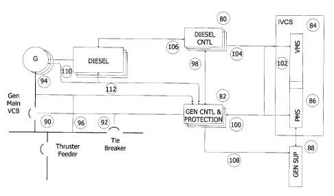
Fig. 9 is a schematic block diagram of the various components of the power
plant according to a preferred embodiment of the invention; and
Fig. 10 is a schematic representation of a typical DP2 Power and Propulsion
plant arrangement.
DESCRIPTION OF PREFERRED EMBODIMENTS OF THE INVENTION
The present invention utilizes droop control in a non-typical configuration,
combined with modern digital control equipment, providing the following:
= ability to identify and clear speed or voltage control failures on
generators;
= intelligent loads with the ability to carry out independent power
management functions to increase plant reliability
= control elements throughout the plant with the ability to determine
percent load on a network through monitoring of voltage and frequency
and to calculate the healthy KVAR and KW values for on line generators.
Typical power plants run in an isochronous or droop corrected configuration
with the frequency and voltage corrected and maintained at the rated values.
This is carried out through correction of any deviation from the rated setting
either by a supervisory system or inherently through a compensation system. In
addition, typical systems have functions designed to correct for real and
reactive load sharing deviations between generator sets operating in parallel.
The specific design of these systems will not be expanded on further within
this
description as they are well known in the art. One of the differences between
the present system and method and typical industrial systems is that the
present system and method, by design does not correct for speed or voltage
droop as a result of the application of real or reactive power. More
specifically,
in accordance with the invention, the plant is allowed to operate in
uncorrected
CA 02678031 2009-08-13
WO 2008/098370 PCT/CA2008/000296
droop configuration. A monitoring unit monitors real-time values and compares
these values to expected values for normal plant operation. If the values
stray
from the expected values, then the control system can analyze the issue and
take corrective action.
5
The invention utilizes the engineering control method of droop configured
within
speed and voltage controllers to carry out the following primary functions:
= Identify deviations from normal droop operation of a generator or prime
mover which indicate an unhealthy condition;
10 = Control intelligent loads to prevent load-induced stress or power system
failure and
= Through understanding of the droop curve and the corresponding KVAR
and KW values identify if alternate measurement devices within the
system have any out of tolerance readings.
The present invention will thus be described in reference for Figures 1-10.
Figures 1-8 illustrate the identification of the various faults identified
herein, and
Figure 10 is a schematic block diagram of a typical power plant in which the
present invention can be used.
Generator and Prime Mover Protection
By utilizing the invention on the power generation portion of the plant, the
severity of a problem can be quantified, and an unhealthy condition can be
acted on, prior to it having a negative influence on the rest of the
electrical or
mechanical network.
For a speed controller, the invention utilizes the pre-programmed constants
for
rated power and droop, and compares the real time variables for speed and
power to the expected values calculated from the pre-programmed droop curve.
Deviations from the expected values can then be acted on based on the
severity and significance of the fault.
RECTIFIED SHEET (RULE 91)
CA 02678031 2009-08-13
WO 2008/098370 PCT/CA2008/000296
11
For a voltage controller, the invention utilizes the pre-programmed constants
for
rated reactive power (or current) and droop and compares the real time
variables for voltage and reactive power (or current) to the expected values
calculated from the pre-programmed droop curve. Deviations from the expected
values can then be acted on based on the severity and significance of the
fault.
The invention provides a proactive approach to system protection and is
designed to supply a protection layer over and above the typical reactive
generator and prime mover protection systems.
Examples of proactive responses to a detected fault(s) include the following:
= Start-up and application of additional generating capacity in anticipation
of potential loss of current, online capacity;
Removal of the faulted generator from the network (typically done by
tripping the circuit breaker);
= Removal of the generator from the network and shutdown of the prime
mover;
= Isolation of the network from other networks (relevant in the case of
redundant bus systems) to provide fault isolation and mitigation;
= Alarm notification to the supervisory system(s) for operator notification
and event logging.
Intelligent Load Controlled Network Protection
Uncorrected or compensated operation in droop for the power plant allows the
invention to provide further system protection and reliability. This is
achieved by
allowing intelligent loads to have an inherent understanding of the plant load
and stress level through their connection to the associated network. Typical
plant arrangements do not provide this ability due to the fact that speed and
voltage droop are typically corrected when the supervisory system sees a
deviation.
CA 02678031 2009-08-13
WO 2008/098370 PCT/CA2008/000296
12
The invention provides a proactive approach to power management, in the most
effective control method possible, by allowing the control to be carried out
at the
lowest control layer possible; at the load itself. Loads are programmed with
the
defined window for frequency and voltage for the system. As bus conditions
approach the boundaries of either of these windows, intelligent loads can
respond proactively. They can be programmed to reduce their contribution to
the network trend by increasing or decreasing real or reactive power as
applicable to assist in correction of the network condition stress.
Examples of load responses to detected bus stress include the following:
= Reduction in power consumption through internal control algorithms
defined by the Process resulting in a corresponding reduction in machine
output.
Reduction in regenerated power applied to the bus to provide correction
when conditions are approaching the upper limit of the load droop curve.
= Measurement of the percentage of real and reactive load by reactive load
compensation equipment to allow correction and system operation at optimal
levels.
The primary objective of the intelligent load control is to allow the plant to
ride
through transient conditions without pushing the bus beyond acceptable
operating conditions. Short duration transients or excursions of minimal
amplitude do not require load reaction. The present invention allows the plant
to
correct for system stressors that could result in full or partial failure of
the plant's
ability to continue providing reliable power. This could occur as a result of
overload or over running of the connected generators. The intelligent loads
provide short term power management through load control. The duration of
accepted interference of the specific plant process to control load beyond the
primary commanded control is dependent on the process and for some
equipment may not be permitted at all. The actions are of short duration and
allow ride-through until supervisory power management functions can adjust the
CA 02678031 2009-08-13
WO 2008/098370 PCT/CA2008/000296
13
plant configuration to allow proper operation within acceptable windows
without
interference at the load level.
While the control algorithms to carry out load adjustment for this process are
relatively simple, the invention requires significant design and coordination
between loads and the supervisory system to be successful and to prevent
harmonic interaction between independent controllers. Depending on the plant,
this process can contain several operationally dependent configurations or
only
a few. This process may be defined in a separate controller or simply through
a
document control matrix defining the control characteristics for each
intelligent
load with respect to this process. However, this again falls within the
purview of
a person skilled in the art.
Calculation of Individual and Combined KW or KVAR
Understanding of droop curve for speed and voltage control allows a control
system to develop monitoring algorithms to determine total plant load as a
percentage total load, the total load the plant in KW and KVAR through
knowledge of each of the generator ratings and the status of the generator (on-
line or off-line) and to determine the health of other portions of the plant
that
determine total or individual KW or KVAR.
Summary
The following functional description provides details of how the system and
method of the present invention can be applied to an installation. It is
important
to note that the process is configured to the requirements of a specific
installation and as such will vary accordingly from system to system.
The present functional description is specific to an upgraded Sedco 700 class
Semi-submersible DP Oil Exploration Platform. The system utilizes a two bus
system and is classed DP2. However, it will be appreciated by a person skilled
CA 02678031 2009-08-13
WO 2008/098370 PCT/CA2008/000296
14
in the art that the system and method of the invention can, with appropriate
modifications, be applied to other types of plants.
Power Plant Protection Process Definition
General
This functional description defines the requirements for implementing this
process in a PLC system - hereafter referred to as the Generator Protection
PLC and for applying the process to other discrete controllers within the
plant.
The PLC provides enhanced generator protection features beyond those
available from the existing protection relays required by Class and code.
Additional control and power management functions that are provided by the
system are also defined, as well as the general functionality of the SWBD
generator controls.
The PLC system is designed to identify critical control faults in the
generator
speed and voltage control systems that are not picked up through the typical
generator protection scheme. On detection of such a fault the system will trip
the generator before the fault results in a cascade failure and possible black
out, or in the event that the fault can not be isolated to a single generator,
the
system will trip the Tie Breaker to provide bus to bus isolation and prevent
further degradation of the condition from affecting both buses.
The system monitors one of more of the following signals in order to achieve
this:
= Generator voltage (from 489 relay)
= Generator frequency (from 489 relay)
= Generator Kilowatts (from 489 relay)
Generator Kilovars (from 489 relay)
= Generator breaker status (from 489 relay)
= Generator field current (from shunt on AVR output)
CA 02678031 2009-08-13
WO 2008/098370 PCT/CA2008/000296
= Generator governor actuator current (from 4-2OmA signal proportional to
actuator output current available on the Woodward 2301 D governor)
= Diesel fuel rack position (from existing rack position transmitter, where
available)
5 SPM-D, 2301 D and DECS Alarm Conditions
The system is designed so that failure of a feedback or monitoring device
within
in the system is detected and announced but does not result in a tripping of
the
associated generator.
Generator Speed Control Fault Monitoring
Key variables that will be utilized within the PLC algorithm to determine
health
of the generator with respect to speed control are:
Breaker Status
= Gen Frequency
= Generator KW
Purpose
Constantly analyze the operating conditions of the generator and apply the
speed control fault detection algorithms to detect faults in the monitored
generator or conditions that indicate another on-line generator is faulty, and
take action to prevent these faults from propagating through the plant and
possibly causing a blackout. The action may be to remove the generator from
the bus, or to open a tie breaker so as to limit the potential power outage to
just
one of the main buses.
User Interface
CA 02678031 2009-08-13
WO 2008/098370 PCT/CA2008/000296
16
Alarm and trip conditions are latched and need to be reset through the user
interface. It is also possible to reset alarms from a push button indicator
mounted on the generator cabinet.
Process
The generator speed control for the system will run in droop mode. When droop
and no-load speed are set the same on all the diesels, units that are
electrically
or mechanically tied together will inherently share the load equally.
Consistent
droop will result in a predictable speed for a given load on a generator based
on
a droop curve, the health of the connected diesel, and the speed control
system. A deviation from this curve beyond an acceptable window is indicative
of an unhealthy status in the diesel (unable to deliver the required KW), a
problem with the speed control system or its control parameters.
All functions are disabled when the generator breaker is open. The system is
to
be designed so that breaker status signal is NO (Normally Open). Loss of the
signal will be represented as the generator being off-line and therefore all
trip
and generator alarm functions will be disabled. This would then trigger an
alarm
on the system if the generator was actually still on line.
All functions will be disabled for 15 seconds following generator breaker
closure
to allow the generator to take on its share of the load.
Following tripping of the generator breaking by the PLC as a result of any of
the
fault conditions listed below, the PLC system will prevent the VMS system from
restarting the generator. If the Multilin Relay trips the generator breaker
within 2
minutes of a previous trip where the current has been greater than a threshold
value I_Trip_Thr, then the PLC will prevent the VMS system from restarting the
generator. In both cases, normal VMS start-generator action will be restored
after the reset button on the generator panel has been pressed.
CA 02678031 2009-08-13
WO 2008/098370 PCT/CA2008/000296
17
Fault Condition 1 - Low Frequency and Low KW
These symptoms occur if there is a loss of engine power, such as from a
sticking injector, fuel pump, dirty fuel filter, incorrectly set ballhead
governor or
limited fuel rack linkage movement. The power generated is below the level
expected for the running speed - as determined from the established normal
speed-load droop curve for the engine, e.g. if the bus frequency is 60 Hz (mid
point on the speed curve and therefore mid-point on the load curve if 60 Hz is
used as the nominal frequency) and the generator has less than 50% of full
load. The other engines on-line are generating more power than they would
have to if all generators were sharing equally, therefore the speed is
slightly
lower than would be expected for normal operation with that load.
When this speed deviation is observed to exceed a preset allowable amount,
and this deviation is maintained for at least a programmed time delay period,
an
alarm will be generated and a `Start-skid' command will be issued to the VMS.
If
the condition deteriorates to a point where the KW signal on the generator is
negative and the diesel is being driven by the bus, and the trend is
maintained
(no evidence of kW recovery), then the system trips the generator after a
programmed time delay.
Fault Condition 1, wherein a generator is not developing the required power,
is
illustrated in Fig. 1. An operating line 10 and a limit 12 of allowable
deviation are
illustrated. Ideally, all operating points should be on the line 10, however a
window 14 is provided between the operating line 10 and the limit 12. A
motoring operating point 16 is illustrated having a negative kW wherein an
alarm, start-skid command and generator will trip if it remains in this zone
for
TD FIt 1 T seconds without any kW recovery. A second operating point 18 is
outside the set of allowable deviation window 14 and will cause an alarm and a
start-skid command if maintained for TD_Flt_1A seconds without any kW
recovery. A third operating point 20 is off the operating line 10, so the
generator
RECTIFIED SHEET (RULE 91)
CA 02678031 2009-08-13
WO 2008/098370 PCT/CA2008/000296
18
or controls are faulty, or the control is misadjusted. However, the third
operating
point 20 is within the window 14, so no trip or alarm.
RECTIFIED SHEET (RULE 91)
CA 02678031 2009-08-13
WO 2008/098370 PCT/CA2008/000296
19
Related Process Variables and Settings - Fault Condition 1
Variable Description Source Type
Name
KW Xdr Generator KWs transducer 489 Al
Load KW Generator KW Int Derived Value
Load Cal Percent of full load = Int Derived Value
(Load KW/KW FL)*100
Freq_Xdr Generator Frequency transducer 489 Al
Spd Hz Generator frequency Int Derived value
from Freq_Xdr
Brk St Breaker status - dry contact from VCB DI
interposing relay
Spd Cal Calculated Hz based on droop curve = Int Derived
Spd NL -(Spd NL - Spd FL)*Load Cal Value, DB
Spd NL No load speed in Hz. Setting from tests. Int DB
Spd_FL Full load speed in Hz. Setting from tests. Int DB
KW FL Full load KW. Int DB
Load Neg True if Load KW < 0 Int Derived Value
Spol_Dev Allowable deviation from curve, Int DB
expressed in Hz and compared to
calculated Hz from droop curve
Fault IA Alarm bit for fault condition 1 - signal Int DB
stays on for 5 sec and then resets.
Alarm remains active in the HMI until it is
acknowledged. This is visible on the
appropriate the HMI screen.
Fault 1 T Trip condition for generator, sends Int Derived
CA 02678031 2009-08-13
WO 2008/098370 PCT/CA2008/000296
breaker trip to 489 via interposing relay, Value, DO
this signal latches and resets when the and DB
breaker is not closed.
Fault 1L This bit latches when SpdFIt1L is active Int Derived
and resets when the operator resets the Value, DO
trips and alarms (ResetGx). This is and DB
visible on the appropriate the HMI
screen.
Spd Dev-F1 Amount by which speed may decrease Int DO
below the no-load speed Spd NL before
it is considered significant - Hz
KW Dev-F1 Amount by which KW may go negative Int DO
before it is considered significant - KW
Reset Gx Reset for alarm and trip conditions on HMI Bit
G1 from the HMI or HW
TD Flt 1A Time the fault condition has to be Int DB
maintained before Fault 1A is
annunciated.
TD Flt 1 T Time the fault condition has to be Int DB
maintained before Fault 1 T is set.
Fault Condition 2 - High Frequency and High KW
These symptoms occur if the speed controller has lost its speed feedback and
5 acts as if the speed is low; or the actuator signal has been lost in the
case of a
reverse acting actuator (where zero actuator current signal represents a max
fuel setting command); or any other control fault occurs that causes more fuel
to
be supplied to the diesel than is required to provide its share of power. It
results
in the diesel delivering more power to the bus than is associated with the
speed
10 load curve of a healthy diesel. For example, if the bus frequency is 60 Hz
(mid
CA 02678031 2009-08-13
WO 2008/098370 PCT/CA2008/000296
21
point on the speed curve and therefore mid-point on the load curve if 60 Hz is
used as the nominal frequency) and the generator has significantly more than
50% of full load, then this is an indication of a problem.
Because the engine is delivering more than its share of the power, the other
on-
line engine(s) are offloaded, resulting in an increase in Hz compared with
what
would be experienced if all the engines were sharing the load equally.
When the speed deviation is observed to exceed a preset allowable amount,
and the deviation is maintained for at least a programmed time delay period,
the
system will generate an alarm and send a 'Start-skid' order to VMS. If this
condition is maintained for at least the programmed time delay period, then
the
generator breaker will also be tripped.
The function contains load and frequency thresholds that are adjusted in
accordance with the specifics of the plant - i.e. generator sizes, ability to
overrun other generators, etc. The thresholds are then adjusted so that a
generator is kept on line even if is off of its droop curve but still
contributing
useful KW to the bus and not imposing additional stress on the bus (frequency
has not approached no load frequency).
Note: In the event of a ballhead backup configuration where the ballhead
governor is active, the curve will be higher with a combination of ballhead
and
electronic controlled skids or all ballhead control. It is imperative that the
trip
curve is above the highest possible ballhead curve (all skids in ballhead mode
-
final configuration of this setting will require testing on site).
To prevent taking a generator off-line when it is still contributing kWs to
the bus
and not causing any stress to the bus system, the following logic is used to
inhibit the trip function:
1) If the Generator load is less than 75% and
2) If the Bus Frequency is below 60.75 Hz (No-load speed 'Spd_NL')
CA 02678031 2009-08-13
WO 2008/098370 PCT/CA2008/000296
22
then disable the trip (alarm function is still active).
Additionally the following conditions will disable the trip:
= frequency is below 60 Hz, this trip is disabled
KW<0
= KW trending is neg
Fault condition 2, wherein the generator is developing too much power, is
illustrated in Fig. 2. An allowable over-speed deviation window 22 is
illustrated.
An operating point 24 is off the operating line, so the generator or controls
are
faulty, or the control is misadjusted. Another operating point 26 is outside
the
window 22 and will cause an alarm and a start-skid order if maintained for
TD_Flt 2A seconds. An operating point 28 inside this region will cause an
alarm, a start-skid order and a breaker trip command if maintained for
TD Flt 2AT seconds.
RECTIFIED SHEET (RULE 91)
CA 02678031 2009-08-13
WO 2008/098370 PCT/CA2008/000296
23
Related Process Variables & Settings - Fault Condition 2
Variable Description Source Type
Name
KW Xdr Generator KWs transducer 489 Al
Load KW Generator KW Int Derived Value
KW FL Full load KW. Int DB
Load Cal Percent of full load - (Load KW/ Int Derived Value
KW FL)*100
Spd NL No load speed in Hz. Setting from tests. Int DB
Spd FL Full load speed in Hz. Setting from tests. Int DB
Freq_Xdr Generator Frequency transducer 489 Al
Spd Hz Generator frequency Int Derived value
from Freq_Xdr
Brk St Breaker status - dry contact from VCB DI
interposing relay
Droop Process variable that is determined from Int DB
2301D setup and measured using actual
tests
Spd Cal Calculated Hz based on droop curve = Int Derived
Spd NL -(Spd NL - Value, DB
SpcL_FL) *Droop *Load Cal
Spd2 Dev Allowable deviation from curve, Int DB
(probably = expressed in Hz and compared to
Spd l_Dev) calculated Hz from droop curve
KW Rat Max Maximum allowable Load KW
expressed as a percentage of Load FL).
Condition has to be maintained for at
CA 02678031 2009-08-13
WO 2008/098370 PCT/CA2008/000296
24
least TD Flt 2A T seconds (with Spd Hz
more than Spd2 Dev above Spd Cal)
before the generator trip command is
issued.
Fault 2A Alarm bit for fault condition 1 - latched Int DB
signal reset by operator through the
HMI.
Fault 2T Trip condition for generator, sends Int Derived
breaker trip to 489 via interposing relay, Value, DO
this signal latches and resets when the and DB
breaker is not closed.
Fault 2L This bit latches when Fault 2T is active Int Derived
and resets when the operator resets the Value, DO
trips and alarms (ResetGx). This is and DB
visible on the appropriate HMI screen.
Reset Gx Reset for alarm and trip conditions on HMI Bit
generator from the HMI or HW
TD Flt 2AT Time the fault condition has to be Int DB
maintained before Fault 2A and
Fault 2T are set.
Fault Condition 3 - High Frequency and Low (negative) KW
These symptoms occur if another skid is faulted (Fault 2) and the capacity of
the faulted generator is greater than the kW load on the bus. If the faulted
generator develops more power than the bus load, the remaining on-line
generator(s) will be motored, and their speed will therefore be at or above
their
no-load speed setting. Normally when this happens the generator protection
system for the faulted generator should trip it off-line (as described in
Fault
Condition 2), and the remaining generators would then automatically be
restored to normal balanced load sharing.
CA 02678031 2009-08-13
WO 2008/098370 PCT/CA2008/000296
Any generator that detects a negative power situation and a speed at or above
no-load speed will automatically generate an alarm and issue a 'Start-skid'
command to the VMS - provided the condition is maintained for at least a
5 programmed delay time. Thresholds of Spd_Dev_F3 (Hz) and KWt_Dev_F3
(kW) will apply. This alarm will be latched for 5 seconds and then
automatically
reset. The applicable alarm will remain active in the HMI but resetting the
bit in
the PLC will allow repeat occurrences to be logged.
10 As backup protection, if the alarm condition is maintained for more than
the
breaker trip time for a high frequency-high power fault (see Fault 2 above),
then
a tie breaker trip command will be issued via a dry contact closure in the PLC
DO module. This trip is also coordinated with the Multlin reverse power trip
to
ensure the PLC trips the tie breaker prior to reverse power tripping of the
15 healthy generator(s).
Fault condition 3 (as detected in a non-faulted generator's Generator
Protection
PLC), wherein a generator is OK but another generator has Fault 2, is
illustrated
in Fig. 3. An operating point 30 is illustrated for the non-faulted generator
that is
20 being motored. An alarm and start-skid command is issued TD_FIt_2AT
seconds after entering this region if there is no kW recovery. A tie trip
command
is issued TD_Flt_StgF34 seconds later if it is still in this region and there
is still
no kW recovery. Multilin reverse power trip is delayed further to allow for
possible isolation of the fault through the tie trip. Another operating point
32 is
25 for the other faulted generator. It has taken on all the system load and
has
enough additional power generation capacity to motor the other generators.
This generator is experiencing Fault 2 and should be tripped oof by its
generator protection system after TD_FIt_2AT seconds.
RECTIFIED SHEET (RULE 91)
CA 02678031 2009-08-13
WO 2008/098370 PCT/CA2008/000296
26
Related Process Variables and Settings - Fault Condition 3
Variable Name Description Source Type
KW Xdr Generator KWs transducer 489 Al
Load KW Generator KW Int Derived Value
Load Neg True if Load KW < 0 (See Fault 1) Int Derived Value
Freq_Xdr Generator Frequency transducer 489 Al
Spd Hz Generator frequency Int Derived value
from Freq_Xdr
Brk St Breaker status - dry contact from VCB Di
interposing relay
Spd NL No load speed in Hz. Setting from Int DB
tests.
Fault 3A Alarm bit for fault condition 3 - Int DB
signal stays on for 5 sec and then
resets. Resetting the bit in the PLC
will allow repeat occurrences to be
logged. Alarm remains active in
the HMI until it is acknowledged.
This is visible on the appropriate
HMI screen.
Fault 3T Trip bit for fault condition 3 having Int Derived Value,
been maintained for longer than DO (Qty 2) and
TD Flt 2AT seconds (see Fault DB
2). Also used to send a `skid start'
signal to VMS. Dry contacts on DO
module.
Fault 3L This bit latches when Fault 3T is Int Derived Value,
active and resets when the DO and DB
CA 02678031 2009-08-13
WO 2008/098370 PCT/CA2008/000296
27
operator resets the trips and
alarms (Reset Gx). This is visible
on the appropriate HMI screen.
Spd Dev_F3 Amount by which speed may Int DO
increase above the no-load speed
Spd NL before it is considered
significant - Hz
KW Dev F3 Amount by which KW may go Int DO
negative before it is considered
significant - KW
Reset Gx Reset for alarm and trip conditions HMI Bit
on G1 from the HMI or HW
TD Flt 2AT See Fault 2 table Int DB
Fault Condition 4 - Low Frequency (> 0) and High KW
These symptoms occur if another skid is faulted and drops load (Fault 1). When
this happens the remaining healthy on-line generators have to increase their
power output, and their speed will therefore drop according to the droop
curve.
Depending on the load conditions and the number of generators on-line, it may
be possible for the remaining generator(s) to become overloaded and for their
speed to drop below the full-load speed. Normally the generator protection
0 system for the faulted generator should trip this generator off-line, and
the
remaining generator(s) would then automatically be restored to normal
balanced load sharing.
Any generator that detects an overload situation and a speed below full-load
5 speed will automatically generate an alarm and issue a `Start-skid' command
provided these conditions are maintained for more than a preset time delay and
there is no movement of the kW towards normal values during this delay.
Thresholds of Spd_Dev_F4 (Hz) and KW_Dev_F4 (KW) will apply. This alarm
CA 02678031 2009-08-13
WO 2008/098370 PCT/CA2008/000296
28
will be latched for 5 seconds and then automatically reset. The applicable
alarm
will remain active in the HMI but resetting the bit in the PLC will allow
repeat
occurrences to be logged.
In the event the speed reduction is maintained beyond the thruster 'Frequency
Spill Over' delay time, the system will trip the tie breaker to prevent total
loss of
power on both buses.
In the event that the current approaches trip conditions for the generator as
a
result of this fault, the PLC will pre-trip the tie breaker as described in
this
document for Fault 17.
The tie trip signal will remain latched to prevent VMS from reclosing the tie
until
the problem has been rectified. The trip signal will be reset when the
momentary HW or HMI reset command is given.
Fault Condition 4 (as detected in a non-faulted generator's Generator
Protection
PCT), wherein a generator is OK by another generator has Fault 1, is
illustrated
in Fig. 4. An operating point 34 for a faulted generator is illustrated. It
has shed
load and the other on-line non-faulted generators have had to take on extra
load. This generator is experiencing Fault 1 and will be tripped off by its
generator protection system if it enters the negative kW region and stays
there
for TD Flt 1T seconds without recovery, or will be tripped on reverse power by
the Multilin relay.
RECTIFIED SHEET (RULE 91)
CA 02678031 2009-08-13
WO 2008/098370 PCT/CA2008/000296
29
Related Process Variables and Settings - Fault Condition 4
Variable Description Source Type
Name
KW Xdr Generator KWs transducer 489 Al
Load KW Generator KW Int Derived
Value
Load Neg True if Load KW < 0 (See Fault Int Derived
1) Value
Freq_Xdr Generator Frequency transducer 489 Al
Spd_Hz Generator frequency Int Derived
value from
Freq_Xdr?
Brk St Breaker status - dry contact VCB DI
from interposing relay
Spd FL Full load speed in Hz. Setting Int DB
from tests.
Fault 4A Alarm bit for fault condition 4 - Int DB
signal stays on for 5 sec and
then resets. Resetting the bit in
the PLC will allow repeat
occurrences to be logged. Alarm
remains active in the HMI until it
is acknowledged. This is visible
on the appropriate HMI screen.
Fault 4T Trip bit for fault condition 4 Int Derived
having been maintained for Value, DO
longer than TD Flt IT seconds (Qty 2) and
(see Faultl ). Also used to send a DB
`skid start' signal to VMS. Dry
CA 02678031 2009-08-13
WO 2008/098370 PCT/CA2008/000296
contacts on DO module.
Fault 4L This bit latches when Fault 4T is Int Derived
active and resets when the Value, DO
operator resets the trips and and DB
alarms (Reset Gx). This is
visible on the appropriate HMI
screen.
Spd Dev-F4 Amount by which speed may Int DO
increase above the no-load
speed Spd NL before it is
considered significant - Hz
KW Dev F4 Amount by which KW may go Int DO
negative before it is considered
significant - KW
Reset Gx Reset for alarm and trip HMI Bit
conditions on tie from the HMI or
HW
TD Flt 1 T See Fault 1 table Int DB
Fault Condition 5 - Actuator Current Abnormal
The system will measure the governor actuator current and, in the event that
5 this current falls below 10% or 0.4 mA (effectively zero) or above 90%, the
system will generate an Actuator Current Abnormal alarm and also forward a
start-skid command to VMS.
Fault Condition 6 - Fuel Rack Position not Tracking Actuator Current
0
The fuel rack position should be linearly related to the actuator current. Any
gross change or irregularity in this relationship is an indication of an
actuator
fault (such as an open actuator coil circuit) or a problem in the linkage.
This type
CA 02678031 2009-08-13
WO 2008/098370 PCT/CA2008/000296
31
of fault condition can deteriorate to a condition where the overall system in
negatively impacted. This condition is therefore monitored and alarmed.
Further
deterioration if not remedied could result in a trip through Fault 1 or Fault
2.
Tracking of this condition and logging in the monitoring DB will assist in
troubleshooting a follow-on trip due to Fault 1 or Fault 2.
The deviation will have to be maintained for a preset delay time before it is
alarmed. This will prevent false alarms due to normal lags in the fuel rack's
dynamic response.
Fault Condition 6, wherein the fuel rack position is not tracking the actuator
current closely enough and there is an actuator or linkage problem, is
illustrated
in Fig. 5. A measured rack position 38 is illustrated within an allowable
deviation
window 40. In addition, measured rack positions 42 are outside the allowable
deviation 40 and an alarm is raised if this condition is maintained for TD_FIt
6A
seconds. A range 44 represents a deviation from expected rack position
transducer output.
RECTIFIED SHEET (RULE 91)
CA 02678031 2009-08-13
WO 2008/098370 PCT/CA2008/000296
32
Related Process Variables and Settings - Fault Condition 6
Variable Description Source Type
Name
Brk St Breaker status - dry contact VCB DI
from interposing relay
Act mA Actuator current in milliamps Current Al
transducer
Rack mA Rack transducer output in mA Current Al
transducer
Rk mA_Cal Calculated rack position signal in Int Derived
mA from: value, DB
Rk mA Cal = m(Rack mA) + C,
where:
(Rk mA URL) - (Rk mA LRL)
(Act mA_URL) -(Act mA_LRL)
(Rk_mA_LRL)
-
m *(Act mA_LRL)
Rk mA Dev6 Allowable deviation in rack Int DB
position signal from calculated
value, Rk mA Cal
Rk mA_ZD Fuel rack position transducer Int DB
output values less than this will
be taken as transducer faults
and will inhibit the breaker alarm
and trip.
Rk mA_URL Upper Range Limit for rack Int DB
position signal - in mA (typically
20mA)
CA 02678031 2009-08-13
WO 2008/098370 PCT/CA2008/000296
33
Variable Description Source Type
Name
Rk mA_LRL Lower Range Limit for rack Int DB
position signal - in mA (typically
4mA)
Act mA_URL Upper range limit value of fuel Int DB
rack actuator current - in mA
(typically 160mA)
Act mA_LRL Lower range limit value of fuel Int DB
rack actuator current - in mA
(typically 160mA)
Fault 6A Alarm bit for fault condition 6. Int DB
Alarm remains active in the HMI
until it is acknowledged. This is
visible on the appropriate HMI
screen.
Fault 6L This bit latches when Fault 6A is Int Derived
active and resets when the Value, DO
operator resets the trip and DB
(Reset Gx). This is visible on the
appropriate the HMI screen and
at the HW indicator on the
4160V switchboard generator
section.
Fault 6 ZD This bit latches if the rack Int DB
transducer output is Rk mA ZD
or less and resets (trip-free)
when the operator resets the trip
(Reset Gx).
CA 02678031 2009-08-13
WO 2008/098370 PCT/CA2008/000296
34
Variable Description Source Type
Name
Reset Gx Reset for alarm and trip HMI Bit
conditions on generator from the
HMI or HW
TD Fit 6A Time fault condition has to be Int DB
maintained before FaulT 6A is
set.
Fault Condition 7 - Generator KW not Tracking Fuel Rack Position (changed to
Actuator Current)
The generator kW should track the fuel rack position. Any gross change or
irregularity in this relationship is an indication of a fuel supply or fuel
quality
problem (water in the fuel, stuck injector, blocked fuel filter, no fuel
supply, etc.).
If this type of fault in not remedied it could result in a trip through Fault
1.
However, it is however possible for a diesel with this type of fault to
continue
supplying KWs for a long period of time - i.e. with half blocked fuel filter.
The appropriate response is therefore to alarm the fault if the deviation
exceeds
a programmed amount and is maintained for a preset delay time, TD_FIt_7A
seconds - the delay preventing false alarms due to normal lags in the engine's
dynamic response. The problem can then be addresses by the watchkeeping
engineer - hopefully before it develops to a Fault 1 tripping condition.
On breaker close, the fault is inhibited for 25 sec to allow soft loading
functions
to be completed and for the generator to reach stable operation.
CA 02678031 2009-08-13
WO 2008/098370 PCT/CA2008/000296
This function was originally designed to monitor rack position but these
transducers proved to be too unreliable on installations encountered so far
and
therefore the function monitors the actuator command instead.
5 Note: This results in less direct fault discrimination - since a Fault 7
alarm could
be caused by a Fault 6 conditions (i.e. Fault 6 AND Fault 7 = Fault 6),
whereas
a Fault 7 alarm on its own is an indication of the intended fault condition
(Fault 7
only = Fault 7). The diagram below shows the originally intended function and
the installed function. In the event the highly reliable rack position sensors
are
10 fitted at anytime in the future, the function can easily be changed over to
utilize
this variable instead of the actuator current.
Fault Condition 7, wherein a generator kW is not tracking the fuel rack
position
closely enough and there is a fuel supply/quality problem, is illustrated in
Fig. 6.
15 A generator kW point 46 is within an allowable deviation window 48. In
addition,
generator kW points 50 are outside the allowable deviation 48 and a generator
breaker is alarmed and tripped if this condition is maintained for TD_FIt_7A
seconds. There is no alarm if the kW is inside a window 52, which is taken as
zero fuel rack position. A range 54 represents a deviation from expected load
20 kW.
RECTIFIED SHEET (RULE 91)
CA 02678031 2009-08-13
WO 2008/098370 PCT/CA2008/000296
36
Related Process Variables and Settings - Fault Condition 7
Variable Description Source Type
Name
Brk St Breaker status - dry contact from VCB DI
interposing relay
Rack mA Rack transducer output in mA Current Al
transducer
Ld KW Cal Calculated KW for rack position Int Derived
transducer signal Rack mA: value, DB
Ld KW Cal = m(Rack mA) + C,
where:
(Load FL)
(Rk mA URL) - (Rk mA LRL)
- m*(Rk mA_LRL)
Ld kW Dev7 Allowable deviation in load KW Int DB
from calculated value,
LdKWCal
Rk mA_ZD Fuel rack position transducer Int DB
output values less than this will
be taken as transducer faults
and will inhibit the breaker alarm
and trip.
Rk mA_URL Upper Range Limit for rack Int DB
position signal - in mA (typically
20mA)
Rk mA LRL Lower Range Limit for rack Int DB
position signal - in mA (typically
4mA)
CA 02678031 2009-08-13
WO 2008/098370 PCT/CA2008/000296
37
Fault 7A Alarm bit for fault condition 7. Int Derived
Alarm remains active in the HMI value, DB
until it is acknowledged. This is
visible on the appropriate HMI
screen.
Fault 7L This bit latches when Fault 7A is Int Derived
active and resets when the Value, DO
operator resets the trip and DB
(Reset Gx). This is visible on the
appropriate HMI screen.
Fault 6 ZD This bit latches if the rack Int DB
(see fault 6) transducer output is Rk mA ZD
or less and resets (trip free)
when the operator resets the trip
(Reset Gx).
Reset Gx Reset for alarm and trip HMI Bit
conditions on generator from the
HMI or HW
TD Flt 7A Time fault condition has to be Int DB
maintained before FaulT 7A is
set.
Fault Condition 8 - Generator Fuel Rack/Actuator Output Hunting (unstable)
This condition can be caused by a number of problems, including deadband in
linkages, droop setting being too low, intermittent connections in the
actuator
and feedback circuits, faulty speed governor electronics, faulty
engine/generator
shaft couplings, etc. At low amplitudes it causes wear of the fuel rack
linkages
and annoyance to operators. At high amplitudes it can result in generator
tripping and risk of blackout.
CA 02678031 2009-08-13
WO 2008/098370 PCT/CA2008/000296
38
When a paralleled generator is hunting, it periodically takes on and sheds
load.
The unfaulted generators are forced to compensate by taking on and shedding
load anti-phase. The total external load may stay constant, apart from any
small
effects due to the hunting induced voltage and Hz variations.
The algorithm specified here is a relatively simple one that would be used for
alarm purposes only and that assumes the PLCs for the online generators will
not be sharing data. The trick then is to distinguish between the effect of
external load variation, which would usually be aperiodic, and hunting induced
load variation, which would be periodic. More sophisticated algorithms and
specialized hardware such as DSP boards may be required to provide the level
of discrimination required for a tie trip decision.
Example of algorithm application:
Every .25 seconds, sample the fuel rack position. Store the last 256
elements in an 256 element array or/and data-block (DB)
= After four successive signals of increasing magnitude are encountered,
flag the sampling intervals count. There will be a minimal set change level
threshold to reduce noise effects, e.g. 0.5 mA.
Look for four successive signals of decreasing amplitude and use this
event to reset to an increasing magnitude search.
= Log time count when the next 4 successive signals of increasing
amplitude are measured,
= Continuously compute the mean value and standard deviation of the
number of sampling intervals between detected signal upswings. These
upswings will be within the sampling time of 256 intervals. At least 4
upswings
have to be detected in this time to provide a meaningful number of values.
= At same time use a min/max signal detection to see the signal spread
over the same period.
Alarm when the standard deviation is less than a set percentage of the
mean, and the difference between the maximum and minimum signal values
exceeds a settable % of the full load value.
CA 02678031 2009-08-13
WO 2008/098370 PCT/CA2008/000296
39
= Display both values in the HMI and allow the HMI to adjust alarm
settings.
To allow for trimming and set up, most of the pre-set values shown above as
fixed values will be adjustable - either through data-block value changes or,
in
the case of the time deviation and the KW excursion, on the the HMI screen.
This function generates an alarm on the HMI and a Generator Control System
summary alarm only. There is no trip function associated with it.
CA 02678031 2009-08-13
WO 2008/098370 PCT/CA2008/000296
Related Process Variables and Settings - Fault Condition 8
Variable Description Source Type
Name
Brk St Breaker status - dry contact from VCB DI
interposing relay
Load KW(Ct Load KW as sampled at the auto Int. Var array Al
Hun Det) incrementing Modulo 256 count
Ct Hun_Det of the number of elapsed
0.25 second intervals since startup.
Using a modulo count limits the array
size to 256 elements, and auto
overwrites the oldest value. Modulo
arithmetic can be used to extract any
value up to 256 intervals old.
Ld KW Max Maximum KW value stored in the array Int Derived value,
Load KW(Ct Hun Det) at any time. DB
Ld KW Min Minimum KW value stored in the array Int Derived value,
Load KW(Ct Hun_Det) at any time. DB
Ld Swg Max Load swing maximum. The level of load Int DB
variation in KW above which an alarm
may be generated if there is evidence of
periodicity. This value will often be
exceeded because of normal load
variation. Default value 100 kW.
Ct KW Sig Minimum number of consecutive Int Derived value,
increasing KW samples, deemed as DB
significant. Default value = 4.
Ld KW Th8 Increase or decrease in consecutive Int DB
samples has to be at least this large to
CA 02678031 2009-08-13
WO 2008/098370 PCT/CA2008/000296
41
Variable Description Source Type
Name
be considered significant. Default value
50 W.
Slope Flag(C Slope Flag(C(Hun Det) array value is Int Derived value
t Hun Det) set to +1 if the preceding Ct KW Sig
array (e.g. 4) sampled values have been
Slope Flag increasing and Slope Flag = -1.
variable Slope Flag value is also set to +1 at this
time. Slope Flag is set back to -1 after a
sequence of Ct KW Sig, e.g. 4,
increasingly negative values. This is to
force the requirement for a downslope
before tagging the next upslope. On
startup Slope Flag is initialized to -1.
Otherwise Slope Flag(C(Hun_Det) is
set to zero. Thus flag array values of +1
mark distinct upsiopes, and the
corresponding array arguments indicate
the time at which they occurred, e.g. if
Slope Flag(10) = 1 and Slope Flag
(240) =1 and the current value of
Ct Hun Det is 10, then the interval
between the detected upslopes is (10 -
240) MOD 256 = 26 time intervals of .25
seconds.
Ct H Mn The mean value of the time between Int DB
detected load or/and instability induced
KW load increases.
Ct H SD The standard deviation for the time Int DB
between detected upslopes. If there are
CA 02678031 2009-08-13
WO 2008/098370 PCT/CA2008/000296
42
Variable Description Source Type
Name
less than 4 flags set in the Slope Flago
array space, the SD is set at Ct H Mn
to avoid an alarm based on too little
data. This limits detection to hunting
time periods below 32 seconds. (This
can be increased by increasing the
sampling time or increasing the array
size.)
Ct SD-M R% Ratio of Ct H SD to Ct H Mn - Int. DB. Derived
expressed as a %. value
Ct SDM RA Value of Ct SD-M R% below which it is Int DB
% judged there is evidence of periodic
behavior. Default value 5%
Fault -8 Alarm bit for fault condition 8. Alarm Int DB
remains active in the HMI until it is
acknowledged. This is visible on the
appropriate HMI screen.
Fault Condition 9 - Generator KW>O with Breaker Open Indication
If the generator breaker status signal indicates the generator breaker is
open,
and the generator KW load signal indicates a load greater than LD_KW
Dev_F9 (the preset deadband to allow for zero calibration errors) and this
condition is maintained for at least TD-Flt-9 seconds (to allow for dynamic
effects) then an alarm will be generated. This would indicate a loss of the
breaker closed signal.
Related Process Variables and Settings - Fault Condition 9
CA 02678031 2009-08-13
WO 2008/098370 PCT/CA2008/000296
43
Variable Description Source Type
Name
Brk St Breaker status - dry contact from VCB DI
interposing relay
KW Xdr Generator KWs transducer 489 Al
Load KW Generator KW Int Derived Value
KW Dev F9 Deadband to allow for zero voltage Int DB
calibration errors. Default value 5 KW.
Fault 9A Set if Load KW indicates a load Int Derived value,
greater than KW Dev F9 and the DB
breaker status Bkr St indicates the
breaker is open.
Fault 9L This bit latches when Fault _9A is Int Derived value,
active and resets when the operator DB
resets the trip (Reset Gx). This is
visible on the appropriate HMI screen.
Reset Gx Reset for alarm condition on HMI Bit
generator from the HMI or HW
TD Flt 9 Time the fault condition has to be Int DB
maintained before it is alarmed and
Fault 9A bit set. Default 5 seconds.
Fault Condition 10 - Breaker Closed Indication and Hz < 45
If the generator breaker status signal indicates the generator breaker is
closed,
and the generator Hz signal indicates a frequency less than Spd_ Dev_F10
(typically set at 45 Hz) then the speed feedback signal is considered faulty
and
an alarm is raised.
CA 02678031 2009-08-13
WO 2008/098370 PCT/CA2008/000296
44
As this speed feedback signal is used for the trip decisions for faults 1 to
4,
these trips are disabled when fault 10 is detected. The alarms are left
enabled.
Related Process Variables and Settings - Fault Condition 10
Variable Description Source Type
Name
Brk St Breaker status - dry contact from VCB DI
interposing relay
Freq_Xdr Generator frequency transducer 489 Al"
Spd Hz Generator frequency Int Derived value
from
Freq_Xdr?
Hz Dev F10 Deadband to allow for zero Hz Int DB
calibration errors. Default value 2 Hz.
Fault 10A Set if Sp_Hz indicates a speed less Int Derived value,
than Hz Dev F10 and the breaker DB
status Bkr St indicates the breaker is
closed.
Fault 10L This bit latches when Fault-10A is Int Derived value,
active and resets when the operator DB
resets the trip (Reset Gx). This is
visible on the appropriate HMI screen.
Reset Gx Reset for alarm condition on HMI Bit
generator from the HMI or HW
TD Flt 10 Time the fault condition has to be Int DB
maintained before it is alarmed and
Fault 10A bit set. Default 5 seconds.
CA 02678031 2009-08-13
WO 2008/098370 PCT/CA2008/000296
Generator Voltage Control Fault Monitoring
Key variables that will be utilized within the PLC algorithm to determine
health
of the generator with respect to speed control are:
5 Breaker Status
= Generator Voltage
= Generator KVAR
Purpose
Constantly analyze the operating conditions of the generator and apply the
voltage control fault detection algorithms to detect faults in the generator
and
generator control system or conditions that indicate another on-line generator
is
faulty, and take action to prevent these faults from propagating through the
plant and possibly causing a blackout. The action may be to remove the
generator from the bus, send a `Start-skid' command to the VMS, open a tie
breaker so as to limit the potential power outage to just one of the main
buses,
or to set an alarm.
User Interface
Alarm and trip conditions are latched and need to be reset through the user
interface.
Process
The generator voltage control for the system will run a droop mode. When
droop and no-load voltage are set the same on all the generators, units that
are
electrically tied together will inherently share the reactive current and
therefore
KVAR equally. Consistent voltage droop will result in a predictable voltage
for a
given KVAR load on a generator based on a droop curve, the health of the
connected diesel, and the voltage control system. A deviation from this curve
CA 02678031 2009-08-13
WO 2008/098370 PCT/CA2008/000296
46
beyond an acceptable window is indicative of an unhealthy status in the
generator (unable to deliver the required KVAR) or a problem with the voltage
control system or its control parameters.
The DECS Basler Excitation units to be used droop purely on reactive current.
At 0 reactive amps there is no voltage droop on the generator whereas at 100%
reactive current there is full droop on the generator - regardless of the kW
load
on the generator.
In the event an unhealthy condition is detected and maintained beyond a
certain
time delay, the PLC is to respond with one or more of the following actions
depending on the type of problem detected: alarm only, alarm and request VMS
to Start-Next Skid, alarm and trip tie breaker, alarm and/or trip the
generator
breaker.
All trip functions are to be disabled when the generator breaker is open. The
system is to be designed so that breaker status signal is NO. Loss of the
signal
will be represented as the generator being off-line and therefore all trip and
generator alarm functions will be disabled. In the event of a wire break on
this
signal, an alarm would be generated on the system if the generator was
actually
still on line (KW>0).
All functions will be disabled for 20 seconds following generator breaker
closure
to allow the generator to take on its share of the load.
Following tripping of the generator breaker by the PLC as a result of any of
the
fault conditions discussed, the PLC system will prevent the VMS system from
synchronizing the generator. Additionally if the Multilin Relay trips the
generator
breaker within 2 minutes of a previous trip, where the current has been
greater
than a threshold value VMS_LO_IL, then the PLC will prevent the VMS system
from synchronizing the generator. In both cases, normal generator availability
will be restored after the fault condition has cleared and the reset button on
the
CA 02678031 2009-08-13
WO 2008/098370 PCT/CA2008/000296
47
generator panel has been pressed or generator lock out has been reset (as
applicable).
Fault Condition 11 - KVAR High, Voltage High or Field Current High
This condition indicates over-excitation, possibly due to a loss of voltage
feedback to the AVR. In the case of loss of feedback for example, the AVR
would see the voltage as low and attempt to increase it by increasing the
field
current. The resulting increase in generator field strength increases the
generator armature winding emf and causes a reactive current to circulate
through the paralleled generators in order to maintain their common output
voltage. The generators are no longer sharing reactive load equally and the
faulty generator can quickly enter an over-current (0/C) situation.
A paralleled generator that has lost feedback will have a reducing power
factor
as it takes on a progressively larger part of the KVAR bus load. The other
unfaulted paralleled generators will have an increasing power factor as they
shed kVAR load. Due to the fact that the system is running in droop, this
condition can be detected by analyzing the voltage on the faulted generator.
If
the voltage is above its expected position on the droop curve then this
generator is seen as faulty and the following actions will be taken:
Alarm and Start-Skid:
If the generator voltage operating point is above the alarm threshold curve
for
greater than a preprogrammed time delay then a trip alarm condition will be
set
and a Start-skid command sent.
Trip Generator VCB:
Trip decisions will be based on two sets of separate trip threshold curves -
one
for over-voltage, and the second for over-field current. One over-voltage
curve
CA 02678031 2009-08-13
WO 2008/098370 PCT/CA2008/000296
48
will be matched with one field over-current curve to cover the situation where
only a few generators are on-line and a small field over-current will cause an
appreciable over-voltage. The other pair of curves will be cover the situation
where a larger number of generators are on line and a larger over-current is
required to produce a smaller over-voltage. If the voltage and field current
operating points are both above their threshold curves for either curve pair,
and
are maintained in this condition for more than a programmed time delay without
any kVAR recovery occurring, then an alarm, a start-skid, and a VCB trip will
be
initiated.
To prevent removal of a generator when it is still contributing kVARs to the
bus,
and is not causing additional stress on the bus, tripping will be disabled if
the
bus voltage is less than nominal (the normal value at mid-range of the kVAR
load).
Fault condition 11, wherein the kVAR, voltage or field current is high and
this is
possibly due to over-excitation on the loss of voltage feedback to AVR, is
illustrated in Fig. 7A. A trip 1 threshold 56, a trip 2 threshold 58, a trip
alarm
threshold 60 and a normal volts droop curve 62 are illustrated. As shown at
64,
tripping will be disabled is kVAR is negative.
A generator voltage 66 is outside the trip alarm threshold 60, so an alarm and
start-skid order will occur if the condition is maintained for TD_Fault_11A
seconds. The generator VCB will also trip if the field current is in the red
zone
for TD-Fault-1 1A seconds without kVAR recovery as it is outside the Trip 1
threshold 56. The generator VCB will also trip if the field current is in the
green
zone for TD-Fault-11A seconds without kVAR recovery as it is outside of the
trip 2 threshold 58.
The deviation from an expected voltage is shown at 68. A generator voltage 70
is outside the trip alarm threshold 60 so an alarm and start-skid order will
occur
if the condition is maintained for TD-Fault-1 1A seconds, regardless of the
field
RECTIFIED SHEET (RULE 91)
CA 02678031 2009-08-13
WO 2008/098370 PCT/CA2008/000296
49
current. The generator VCB will also trip is the field current is in the red
zone for
TD-Fault-11A seconds without kVAR recovery as it is outside the trip 1
threshold 56.
With reference to a generator voltage 72, if the field current is not in the
red
zone, then there will be no alarm, no trip as the voltage is below the alarm
threshold 60. If the field current is in the red zone, the alarm will trip and
a start-
skid command will be sent and a VCB trip will occur if it is maintained for
TD-Fault-11A seconds without kVAR recovery, as it is outside the Trip 1
threshold 56.
With additional reference to Fig. 7B, the current for unfaulted generators is
on a
line 74. A green zone 76 is shown above the line 74, wherein voltage is
larger,
the deviation is positive and a smaller number of generators are on-line. A
red
zone 78 is shown above the green zone 76 wherein the voltage is smaller, the
deviation is positive and a larger number of generators are online.
Related Process Variables and Settings - Fault Condition 11
Variable Description Source= Type
Name ..,
Brk St Breaker status - dry contact from interposing VCB DI
relay
KW Xdr Generator KWs transducer 489 Al
KVAR Xdr Generator KVAR transducer 489 Al
Load KW Generator KW Int Derived
value, from
KW Xdr
Load KVAR Generator KVAR Int Derived
value, from
KVAR Xdr
RECTIFIED SHEET (RULE 91)
CA 02678031 2009-08-13
WO 2008/098370 PCT/CA2008/000296
Variable Description Source Type
Name
PF Power factor, calculated from: PF = Int Derived
Load-KW/[(Load KW)A2+(Load KVAR)^2J^0.5.
The normal value is around 0.8.
PF Min Minimum allowable generator PF. Default 0.6 Int DB
TD Flt i IA Time in seconds PF has to be less than Int DB
PF Min before the alarm condition is reached.
Default value - 5 seconds.
Fault IIA Set if PF has been less than PF Min with +'ve Int Derived
KVAR for at least TD Flt 9IA seconds. Reset value, DB
automatically after 5 seconds. Resetting the bit
in the PLC will allow repeat occurrences to be
logged. Alarm remains active in the HMI until it
is acknowledged. This is visible on the
appropriate HMI screen.
KV Xdr Generator KV transducer 489 Al
Load KV Generator KV Int Derived
value, from
KV Xdr
Ld KV Max Generator KV maximum. Default value TBD. Int DB
Fld A_Xdr Generator field current transducer. Shunt Al
resistor &
voltage
transducer.
Fld Amp Generator field current in amps. Int. Derived
value, from
Fld A Xdr
CA 02678031 2009-08-13
WO 2008/098370 PCT/CA2008/000296
51
Variable Description Source Type
Name
Fld A_Max Generator field amps maximum. Default value Int DB
TBD
Fault l I T Trip bit for fault condition 11. Used to open Int Derived
generator breaker and issue a skid start value, DO,
command. This bit is set when Fault 11A is DB
active AND (Load KV exceeds Ld KV Max,
OR Fld Amp exceeds Fld A-Max).
Fault IIL This bit latches when Fault _11T is active and Int Derived
resets when the operator resets the trip value, DB
(Reset Gx). This is visible on the appropriate
HMI screen.
Reset Gx Reset for latched alarm condition on generator HMI Bit
from the HMI or HW
Fault Condition 12 - WAR Low, Voltage Low or Field Current Low
This condition indicates under-excitation due to a fault in the AVR or in the
generator field circuit. The resulting decrease in generator field strength
reduces the generator armature winding emf and causes a reactive current
(opposite in phase to that of fault 11) to circulate through the paralleled
generators in order to maintain their common output voltage.
As the faulted generator loses excitation it will reduce its contribution to
the
WAR bus load and its power factor will go up. The other unfaulted paralleled
generators will have a decreasing power factor as they take on more WAR
load. High power factor or -'ve WAR combined with low voltage are therefore
indications of a potential excitation problem.
CA 02678031 2009-08-13
WO 2008/098370 PCT/CA2008/000296
52
Due to the fact that the system is running in droop, this condition can be
detected by analyzing the voltage on the faulted generator and comparing it to
its expected value as read from the droop curve:
1) If the generator voltage operating point is below the trip alarm threshold
curve and the kVAR is negative (as programmed), and this condition is
maintained for longer than a preprogrammed time delay, then an alarm
condition will be set.
2) If the generator voltage operating point is below the calculated trip
threshold
curve value and stays there for longer than a preprogrammed time delay, then a
trip VCB order will be issued if the kVAR is negative.
3) To assisting in detecting this fault when the number of on-line generators
prevents the bus voltage falling below the preprogrammed trip level, the
system
also looks at field current and voltage. If the field current is less than 10%
of
nominal AVR output, and the voltage is slightly low (preprogrammed value
currently set at 0.5% of rated no load voltage), then the system will also
assume
there is a fault, and will alarm and trip the VCB.
CA 02678031 2009-08-13
WO 2008/098370 PCT/CA2008/000296
53
Related Process Variables and Settings - Fault Condition 12
Variable Description Source Type
Name
Brk St Breaker status - dry contact from interposing VCB DI
relay
KW Xdr Generator KWs transducer 489 Al
KVAR Xdr Generator KVAR transducer 489 Al
Load KW Generator KW Int Derived
value, from
KW Xdr
Load KVAR Generator KVAR lnt Derived
value, from
KVAR Xdr
PF Power factor, calculated from: PF = Int Derived
Load KW/((Load KW)A2+(Load KVAR)^2J^0.5.
The normal value is around 0.8.
PF Max Maximum allowable generator PF. Default 1 Int DB
TD Flt 12A Time in seconds PF has to be more than Int DB
PF Max OR the KVAR has been -`ve before
the alarm condition is reached. Default value: 5
seconds.
Fault 12A Set if PF has been more than PF Max OR the Int Derived
KVAR has been negative for at least value, DB
TD Flt 12A seconds. Reset automatically after
seconds. Resetting the bit in the PLC will
allow repeat occurrences to be logged. Alarm
remains active in the HMI until it is
acknowledged. This is visible on the
appropriate HMI screen.
CA 02678031 2009-08-13
WO 2008/098370 PCT/CA2008/000296
54
Variable Description Source Type
Name
KV Xdr Generator KV transducer 489 Al
Load KV Generator KV Int Derived
value, from
KV Xdr
Ld KV Min Generator KV minimum. Default value TBD. Int DB
Fld A Xdr Generator field current transducer. Shunt Al
resistor &
voltage
transducer.
Fid Amp Generator field current in amps. Int. Derived
value, from
Fld A_Xdr
Fld A- Min Generator field amps minimum. Default value Int DB
TBD
Fault 12T Trip bit for fault condition 12. Used to open Int Derived
generator breaker and issue a skid start value, DO,
command. This bit is set when Fault 12A is DB
active AND (Load KV is less than
Ld KV Min, OR Fld Amp is less than
Fld A_Min).
Fault 12L This bit latches when Fault 12T is active and Int Derived
resets when the operator resets the trip value, DB
(Reset Gx). This is visible on the appropriate
HMI screen.
Reset Gx Reset for latched alarm condition on generator HMI Bit
from the HMI or HW
CA 02678031 2009-08-13
WO 2008/098370 PCT/CA2008/000296
Fault Condition 13 - Power Factor Low Leading, KVAR Low (Negative)
This is an indication that another generator maybe suffering from an over-
excitation fault condition 11 but has not tripped out in the expected time,
5 TD_FIt_1 1A seconds. It will raise an alarm based on power factor remaining
low
and leading or voltage remaining and approaching the over voltage setpoint
defined in the protection relay.
In the event that the system reaches the negative KVAR minimum trip level set
10 in the Multilin plus a percentage offset, the system will trip the Tie
before the
preset trip time in the Multilin to isolate the problem.
In the event that the current approaches trip conditions for the generator,
the
PLC will pre-trip the Tie and as described in this document under Fault 17.
In the event that the voltage is above the voltage threshold defined in the
the
protection relay the PLC will pretrip the Tie to isolate the fault. As this is
more of
a bus related issue, this function may be carried out in an alternate device
if
available - i.e. a feeder protection relay.
Related Process Variables and Settings - Fault Condition 13
Variable Description Source Type
Name
Brk St Breaker status - dry contact from interposing VCB DI
relay
KW Xdr Generator KWs transducer 489 Al
KVAR Xdr Generator KVAR transducer 489 Al
Load KW Generator KW Int Derived
value,
from
CA 02678031 2009-08-13
WO 2008/098370 PCT/CA2008/000296
56
Variable Description Source Type
Name
KW Xdr
Load KVAR Generator KVAR Int Derived
value,
from
KVAR Xdr
PF Power factor, calculated from: PF = Int Derived
Load KW/((Load KW)A2+(Load KVAR)^2]^0.5.
The normal value is around 0.8.
PF Max Maximum allowable generator PF. Default 1.0 Int DB
(same as
for Fault
Condition
12)
TD Flt 11A Time in seconds PF has to be more than Int DB
(same as PF Max OR the KVAR has been -'ve (leading)
for Fault before the alarm condition is reached. Default
Condition value: 5 seconds.
11)
Fault 13A Set if PF has been more than PF Max OR the Int Derived
KVAR has been -'ve (leading) for at least value, DB
TD Flt I IA seconds. Reset automatically after
seconds. Resetting the bit in the PLC will
allow repeat occurrences to be logged. Alarm
remains active in the HMI until it is
acknowledged. This is visible on the
appropriate HMI screen.
KV Xdr Generator KV transducer 489 Al
CA 02678031 2009-08-13
WO 2008/098370 PCT/CA2008/000296
57
Variable Description Source Type
Name
Load KV Generator KV Int Derived
va006Cue,
from
KV Xdr
Ld KV Max Generator KV maximum. Default value TBD. Int DB
(same as
for Fault
Condition
11)
Fault 13T Trip bit for fault condition 13. Used to open tie Int Derived
breaker. This bit is set when Fault 13A is active value, DO,
AND Load KV exceeds Ld KV Max.. DB
Fault 13L This bit latches when Fault 13T is active and Int Derived
resets when the operator resets the trip value, DB
(Reset Gx). This is visible on the appropriate
the HMI screen.
Reset Gx Reset for latched alarm condition on generator HMI Bit
from the HMI or HW
Fault Condition 14 - Power Factor Low Lagging, KVAR High (Positive)
This is an indication that another generator is suffering under-excitation
fault
condition 12 but has not tripped out in the expected time, TD_Flt_12A seconds.
It will raise an alarm based on the power factor remaining low and lagging and
KVAR being high (positive).
CA 02678031 2009-08-13
WO 2008/098370 PCT/CA2008/000296
58
In the event that the system reaches the positive KVAR minimum trip level set
in the Multilin less a percentage offset, the system will trip the Tie before
the
preset trip time in the Multilin to isolate the problem.
In the event that the current approaches trip conditions for the generator,
the
PLC will pre-trip the Tie as described in this document under Fault 17.
Related Process Variables and Settings - Fault Condition 14
Variable Description Source Type
Name
Brk St Breaker status - dry contact from interposing VCB DI
relay
KW Xdr Generator KWs transducer 489 Al
KVAR Xdr Generator KVAR transducer 489 Al
Load KW Generator KW Int Derived
value, from
KW Xdr
Load KVAR Generator KVAR Int Derived
value, from
KVAR Xdr
PF Power factor, calculated from: PF = Int Derived
Load KWI[(Load KW)^2+(Load KVAR)^2]^0.5.
The normal value is around 0.8.
PF Min Minimum allowable generator PF. Default 0.6 Int DB
(same as for
Fault
Condition
11)
TD Flt 12A Time in seconds PF has to be less than Int DB
CA 02678031 2009-08-13
WO 2008/098370 PCT/CA2008/000296
59
Variable Description Source Type
Name
(same as for PF Min AND KVAR +'ve (lagging) before the
Fault alarm condition is reached. Default value - 5
Condition seconds.
12)
Fault 14A Set if PF has been less than PF Man AND Int Derived
KVAR +'ve for at least TD Flt 12A seconds. value, DB
Reset automatically after 5 seconds. Resetting
the bit in the PLC will allow repeat occurrences
to be logged. Alarm remains active in the HMI
until it is acknowledged. This is visible on the
appropriate HMI screen.
KV Xdr Generator KV transducer 489 Al
Load KV Generator KV Int Derived
value, from
KV Xdr
Ld KV Min Generator KV minimum. Default value TBD. Int DB
Fault 14T Trip bit for fault condition 14. Used to open tie Int Derived
breaker. This bit is set when Fault-14A is active value, DO,
AND Load KV is less than Ld KV Min. DB
Fault 14L This bit latches when Fault 14T is active and Int Derived
resets when the operator resets the trip value, DB
(Reset Gx). This is visible on the appropriate
HMI screen. L
Reset Gx Reset for latched alarm condition on generator HMI Bit
from the HMI or HW
Fault Condition 15 -- Unstable Voltage Control - Hunting
CA 02678031 2009-08-13
WO 2008/098370 PCT/CA2008/000296
This condition can be caused by the voltage droop setting being too low, AVR
gain too high, by faulty AVR electronics or by an unstable load. At low
amplitudes it causes annoyance to operators. At high amplitudes it can result
in
generator tripping and risk of blackout.
5
When a paralleled generator is hunting, it periodically takes on and sheds
reactive load. The unfaulted generators are forced to compensate by taking on
and shedding reactive load anti-phase - the external reactive load staying
constant, apart from any changes due to voltage fluctuations.
The algorithm that will be specified here is a relatively simple one that
would be
used for alarm purposes only and that assumes the PLCs for the online
generators will not be sharing data. The trick then is to distinguish between
the
effect of external reactive load variation, which would usually be a periodic,
and
hunting induced reactive load variation, which would be periodic. More
sophisticated algorithms and specialized hardware such as DSP boards may be
required to provide the level of discrimination required for tie trip
decisions.
Fault Condition 15B, which follows, assumes that facilities are provided for
sharing data between the generator PLCs, or that total KVAR load is available
from another source, such as VMS. The algorithm is then much simpler.
This function generates an alarm on the HMI and a Generator Control System
summary alarm only. There is no trip function associated with it.
Example of simple algorithm application:
= Every .25 seconds, sample the generator KVAR. Store the last 256
elements in an 256 element array or/and DB
= After four successive signals of increasing magnitude are encountered
flag the sampling intervals count. There will be a minimal set change
level threshold to reduce noise effects, e.g. 50 watts.
CA 02678031 2009-08-13
WO 2008/098370 PCT/CA2008/000296
61
= Look for four successive signals of decreasing amplitude and use this
event to reset to an increasing magnitude search.
= Log time count when next 4 successive signals of increasing amplitude
are measured.
= Continuously compute the mean value and standard deviation of the
number of sampling intervals between detected KVAR upswings. These
upswings will be within the sampling time of 256 intervals. At least 4
upswings have to be detected in this time to provide a meaningful
number of values.
= At same time use a min/max kVAR detection to see the KVAR spread
over the same period.
= Alarm when the standard deviation is less than a set percentage of the
mean, and the difference between the maximum and minimum KVAR
values exceeds a settable % of the full load value.
= Display both values in the HMI and allow the HMI to adjust alarm
settings.
To allow for trimming and set up, most of the pre-set values shown above as
fixed values will be adjustable - either through DB value changes or, in the
case
of the time deviation and the KW excursion, on the HMI screen.
Related Process Variables and Settings - Fault Condition 15
Variable Description Source Type
Name
Brk St Breaker status - dry contact from VCB DI
interposing relay
Load KVAR( Load KW as sampled at the auto Int. Var array Al
Ct Hun Det) incrementing Modulo 256 count
Ct Hun Det of the number of elapsed
0.25 second intervals since startup.
CA 02678031 2009-08-13
WO 2008/098370 PCT/CA2008/000296
62
Variable Description Source Type
Name
Using a modulo count limits the array
size to 256 elements, and auto
overwrites the oldest value. Modulo
arithmetic can be used to extract any
value up to 256 intervals old.
L KVAR Max Maximum load KVAR value stored in the Int Derived value,
array Load KVAR(Ct Hun_Det) at any DB
time.
L KVAR Min Minimum load KVAR value stored in the Int Derived value,
array Load KVAR(Ct Hun Det) at any DB
time.
LR Swg Max Load reactive swing maximum. The Int DB
level of load variation in KVAR above
which an alarm may be generated if
there is evidence of periodicity. This
value will often be exceeded because of
normal load variation. Default value
100 WAR.
C KVAR Sig Minimum number of consecutive Int Derived value,
increasing KVAR signal samples, DB
deemed as significant. Default value
4.
L KVAR Th8 Increase or decrease in consecutive Int DB
samples has to be at least this large to
be considered significant. Default value
50 VAR.
SI FIg R(Ct Slope flag reactive. Int Derived value
Hun Det) S1 Flg R(Ct Hun Det) array value is
CA 02678031 2009-08-13
WO 2008/098370 PCT/CA2008/000296
63
Variable Description Source Type
Name
array set to +1 if the preceding C KVAR Sig
SI_FIg R (e.g. 4) sampled values have been
variable increasing and SI F1g R = -1. S1 Fig R
is also set to +1 at this time. S1 F1g R is
set back to -1 after a sequence of
Ct KVAR Sig, e.g. 4, increasingly
negative values. This is to force the
requirement for a downslope before
tagging the next upslope. On startup
Sl F1g R is initialized to -1. Otherwise
Sl F1g R(Ct Hun Det) is set to zero.
Thus flag array values of +1 mark
distinct upslopes, and the corresponding
array arguments indicate the time at
which they occurred, e.g. if
SI F1g R(10) = 1 and S1 F1g R(240) =1
and the current value of Ct Hun Det is
10, then the interval between the
detected upslopes is (10 - 240) MOD
256 = 26 time intervals of .25 seconds.
C H R Mea Count hunting reactive mean. The mean Int DB
n value of the time between detected load
or/and instability (hunting) induced
KVAR load increases.
C H R SD Count hunting reactive standard Int DB
deviation. The standard deviation for the
time between detected (hunting)
upslopes. If there are less than 4 flags
set in the S1 F1g RO array space, the
CA 02678031 2009-08-13
WO 2008/098370 PCT/CA2008/000296
64
Variable Description Source Type
Name
SD is set at C H R Mean to avoid an
alarm based on too little data. This limits
detection to hunting time periods below
32 seconds. (This can be increased by
increasing the sampling time or
increasing the array size.)
SD- Standard deviation to mean - count ratio Int. DB. Derived
Mean R% in %: C H R SD*100 /C H R Mean value
SD-Mn RA% Value (Allowable) of SD-Mean-R% Int DB
below which it is judged there is
evidence of periodic behavior. Default
value 5%
Fault-1 5 Alarm bit for fault condition 15. Alarm Int DB
remains active in the HMI until it is
acknowledged. This is visible on the
appropriate HMI screen.
Fault Condition 16 - Loss of Exciter Current
This would occur if the field circuit is opened, if there a loss of AVR output
due
to an AVR fault or if there was a sensing circuit problem. In the event that
this
occurs the system will generate an alarm notifying the operator that there is
a
problem. This alarm is only active when the VCB is closed. In the event that
the
generator has actually lost excitation, this fault would be followed
immediately
by a fault 12 condition and the generator would be tripped off line.
A threshold current value of Fld Amp_Th will apply. Actuator currents within
this window will be judged as zero. This alarm will be latched for 5 seconds
and
CA 02678031 2009-08-13
WO 2008/098370 PCT/CA2008/000296
then automatically reset. The alarm will remain active in the HMI but
resetting
the bit in the PLC will allow repeat occurrences to be logged.
As this is a critical signal for Faults 12, and will disable the exciter
current
5 related portion of the logic when in alarm condition.
Related Process Variables and Settings - Fault Condition 16
Variable Description Source Type
Name
Brk St Breaker status - dry contact from VCB DI
interposing relay
Fld A Xdr Generator field current transducer. Shunt resistor Al
& voltage
transducer.
Fld Amp Generator field current in amps Current Al
transducer
Fld Amp Th Threshold absolute value (in A) below Int DB
which the actuator current will be
judged to be zero.
Fault 16A Alarm bit for fault condition 16. Alarm Int DB
remains active in the HMI until it is
acknowledged. This is visible on the
appropriate HMI screen.
Fault 16L This bit latches when Fault 16A is Int Derived Value,
active and resets when the operator DO and DB
resets the trip (Reset Gx). This is
visible on the appropriate HMI screen.
CA 02678031 2009-08-13
WO 2008/098370 PCT/CA2008/000296
66
Reset Gx Reset for alarm and trip conditions on HMI Bit
generator from the HMI or HW
Fault Condition 17 - Sustained Current Overload Trip
The Multin SR489 Relay is the primary method for protecting the generator from
the effect of sustained current overload from any cause - whether induced by a
failure of the generator's control systems, or due to a failure or overload on
the
connected bus.
The generator protection system PLC will provide backup secondary protection
and improved fault isolation by prior tripping of the tie breaker if the KVAR
is
lagging (+), or if the KVAR is leading (-). Here the word 'prior' is used to
indicate
tripping a fixed number of seconds before the SR489 would otherwise trip the
generator breaker because of the sustained current overload. If the
overcurrent
condition continues after the tie breaker has tripped, the generator breaker
will
be tripped by the 489 Relay.
The PLC initiated tie breaker trips will be alarmed on the HMI and will cause
the
red fault indicator light (device -H FLT) on the generator panel door to come
on.
Both the alarms and the trips will be latched. Reset will be via the HMI or HW
(device -S RST) reset buttons.
The method used to achieve this backup protective action is as follows (see
Figure 8):
If the actual generator current (Ia)* exceeds the overload protection
pickup point (Ipu - set at 434A), the PLC is to start timing. The PLC is then
to
calculate the time it will take the Multilin SR489 relay to trip the generator
breaker on overload.
The overload protection curve currently programmed in the Multilin SR489
relays for this installation is:
CA 02678031 2009-08-13
WO 2008/098370 PCT/CA2008/000296
67
ANSI Extremely Inverse Curve with a multiplier setpoint (M) of 0.42.
Notice that the K, E constants for this curve are 0.140 and 0.020
respectively.
After the calculation, the PLC is to trip the tie breaker 2 seconds before the
calculated time it will take the SR489 to trip the generator (note this timing
is
approximate). If the overload condition disappears before the timer has timed
out, the operation is to be cancelled and the timer is to be reset.
*The actual generator current is calculated as follows:
la = Load Amps = [(Load_KW^2 + Load_KVARA2)^0.5]/[1.73*Load_KV]
Additional Miscellaneous Functions
Fault Condition 18 - SPM-D, 2301 D and DESC Fault Monitoring
Due to a lack of available points on the Multilin SR489 Relay, the PLC will be
used to provide monitor the status of these three devices through paralleled
auxiliary contacts (OR'd) providing an input to the PLC. The PLC will monitor
this input, if this input goes high the system will initiate and alarm at the
HMI
and locally at the generator cabinet. The condition is also used in the Tie
Trip
logic and will result in the Tie Breaker being tripped.
Fault Condition 19 - System Health
Through the system self monitoring described in more detail later in this
document, in the event of a system health fault, the PLC disables all of the
its
alarm and trip functions with the exception of a system health alarm in the
HMI
and the local digital alarm output if it is available.
CA 02678031 2009-08-13
WO 2008/098370 PCT/CA2008/000296
68
It is important to note that local alarm circuit is failsafe and that in the
event of
any failure in the PLC or associated alarm output wiring, local alarm
indication
will be active through a separate 110 VDC supply and the VMS will receive an
alarm through loss of signal to the 489/Gen Prot system alarm.
Fault Condition 20 - Failure to Operate
Additional self monitoring is included in the system that monitors the
expected
feedback when ever the system takes action. i.e. when the system issues a
VCB Trip command it will monitor the system for feedback that the breaker
status is open within a preset time delay. In the event that there is no
feedback,
the system will issue an alarm.
Fault Condition 21 - VMS Lockout Function
The Multlin 489 design does not accommodate the logic functions necessary to
determine if reclose of a generator breaker after a long time over current
trip is
the appropriate action to take or if VMS should be prevented from being able
to
attempt a reclose. The Generator protection PLC is to be used to supervise
this
function by R1 hold function. This function holds the VCB trip signal to the
Multilin high (and therefore R1 output on the Multilin high) long enough trip
the
K TR and lockout the generator through the 86 relay.
Whether a generator recloses should be based on whether the overload was
load related or bus related. If the fault is load related then when the
generator
trips the breaker it is likely the that load will be cleared from the bus
after power
has been lost. In the event that the over load is on the bus then the
generator
will trip on overload each time it is closed - this is undesirable but so is a
situation where a generator is healthy, the bus is healthy yet the generator
is
not accessible to the VMS.
CA 02678031 2009-08-13
WO 2008/098370 PCT/CA2008/000296
69
The system has been programmed to circumvent these two issues through the
incorporation of the following logic:
Load Related Fault:
If a generator trips on over current the PLC will take no action if there have
been no other trips in the last 2 minutes. This is based on a preset time
delay
programmed in the PLC. Therefore if the trip is load related and the faulted
load
clears after loss of power, then the VMS will reclose the breaker and the
generator should stay on line.
Bus Related Fault:
If the fault is bus related then the VMS will reclose and then trip again on
over
current. If the PLC see a VCB status of: open-closed-open within a two minute
window and if at any time during the period that the breaker was closed and
the
generator current was over 90% rated current, then the PLC will prevent the
VMS from carrying out future closes through VMS lock out function and the 86
relay.
Generator Protection Trip Faults
In the event of a Fault 1,2,11 or 12. The system will allow the generator 2
attempts to reclose if it is available. After the second failed attempt the
Generator Protection PLC will lockout the generator and provide an VMS lock
signal.
Fault Condition 22 - Fault Override Tie Sync Bias Active
The system provides synchronization across the tie breaker by biasing the
speed on Bus A generators (G1-3). As a result there are normal operational
configurations where the generators on Bus A can have a speed bias applied to
CA 02678031 2009-08-13
WO 2008/098370 PCT/CA2008/000296
them when on load to facilitate synchronization across the Bus Tie. This speed
bias will push a deviation from the droop curve for the Bus A Generators, each
standalone Generator protection PLC must disable Fault 1-4 governor trips and
alarms during the period this bias is active.
5
This feature has also been added to B Bus Generators. Although there is no
physical way of having a speed bias injected from the Tie SPM-D, this will
still
provide additional protection in the event that there is a K_52A relay fault
that
allows the generators SPMD to bias the governor speed when it is on line.
To accomplish this the system monitors the sync bias voltage on T191T20 and if
the breaker is closed and there is voltage on these terminals (Tie SPMD is
attempting a sync or there is a system fault that result in voltage being
applied
to these terminals), then the system inhibits the governor faults 1-4 until
the
condition has cleared.
Generator Protection System Self-Monitoring & Special Functions
Programmed Self Monitoring
The PLC program uses available module and communication diagnostics to
prevent the system issuing false alarm and trip signals in the event of a PLC
fault, and to provide fault discrimination via PLC LED indications or/and the
HMI
alarms:
I/O module faults detected by the CPU will cause all generator protection
system trips and alarms for that generator to be inhibited, and a PLC I/O
Module Fault for that generator's protection system to show on the HMI. When
the faults are cleared the alarms and trips will automatically be reset and
then
re-enabled. The fault will have to be acknowledged on the screen before the
I/O
module fault indication will be removed.
CA 02678031 2009-08-13
WO 2008/098370 PCT/CA2008/000296
71
Diagnostic messages from faulted Al Modules will be used to discriminate the
fault in the HMI:
= External auxiliary supply lost
= Configuration error
= Wire break
= Signal over-range/under-range
Diagnostic messages from faulted DI/DO modules will be used to discriminate
the fault in the HMI (or alternative acceptable means):
= Internal/External auxiliary voltage missing
= Configuration error
= Fuse in module defective
= Defective module
A Generator Protection PLC FMECA will be required to detail all possible PLC
system failure modes and the design action taken to minimize their effects.
The
effectiveness of these measures is to be demonstrated in the FAT.
Loss of PLC Power
Latched trip signals will go to their released status on loss of PLC power.
GE Multilin 489 Relay Data Capture
Any time the generator protection system generates an alarm it will capture
the
Multilin database. Up to 10 sets of data will be captured to facilitate
trouble-
shooting of cascading faults. Each set of data will be time-stamped with the
Multilin Relay time stamp and the PLC time stamp, and will include the alarm
ID
e.g. 'Fault 16' as per the 489 Relay documentation.
Base Load Diesel Function
CA 02678031 2009-08-13
WO 2008/098370 PCT/CA2008/000296
72
As a maintenance item, the VMS has been set up with a method of allowing the
operator to load up a generator so that it has a disproportional amount of the
plant load. Without monitoring of this function the generator protection
system
would trip a skid that was in this mode based on a Spd Control related fault.
The system has been designed to integrate the base load function from both a
generator control and protection point of view.
Base load is selected by the operator through the Base Load select switch at
each generator cubicle, the PLC provides the signals and logic necessary to
switch the control of the 2301 D to a Load Control Mode, to provide the 2301 D
with the load reference required to carry out the Base Load function and to
provide continued speed control failure protection to the power generation
system while in the Base Load mode.
When Base Load is selected the control system carries out the following
actions:
1) activates relay K_LCNTL - this sets the Droop / Isochronous input
high in on the 2301 D and sets the controller to load control mode (ref:
analog
input 2, T22&23). Load control indication at the SWBD and on the HMI will be
ON.
2) The analog output (AO01) from the PLC, constantly mirrors the
current load in the form of a 0-5 VDC signal that represents 0-100% load -
when the function becomes active the this output then switches from 'Load
Follow-up' mode to 'Ramp to Base Load Target' mode. The `Target Base Load'
is defined by the 0-5 VDC PLC input provided through the voltage divider and
pot (-R2), this signal represents a 0-100% load reference.
3) The engine is then in closed loop KW control at the 2301 D.
4) When the `Base Load' select switch is switched back to 'Droop',
the system ramps from the 'Target Base Load' to a KW value calculated from
CA 02678031 2009-08-13
WO 2008/098370 PCT/CA2008/000296
73
the bus frequency and droop curve. This is a dynamic target - i.e. it will
change
based on the percent loading of the other on-line generators.
5) When the calculated KW reference equals the calculated KW for
bus frequency, the system will revert to Droop Mode by de-energizing
K_LCNTL. The system will then be back in `Droop' mode, `Load Cntl Active'
indication on the SWBD and the HMI will be OFF.
6) In the event any of the following occurs, the system will revert to
'Droop' mode immediately.
a) the system monitors a load deviation exceeding a preset
value for longer than a preset time delay.
b) there is a deviation between the load reference and load
reference feedback that exceeds a preset value for a preset time.
c) the system bus frequency is higher or lower than the
nominal frequency range of 59.25 - 60.75 Hz for longer than a preset
time delay
d) base load function times out based on an operator preset
function timer (available to set from the HMI with a range of 0-60
minutes)
e) Any time the Base Load is de-activated and the Droop/Base
Load switch is in the 'Base Load' position, the Alarm indication on the
SWBD will flash and the HMI will display `Base Load Control Error'.
f) Any time the system is automatically removed from Base
Load or set to Base Load when it is disabled, a 'Gen Cntl Common'
alarm is generated by the PLC and sent to the VMS - this condition
clears when the Droop/Base Load switch is switch back to 'Droop' and
the Alarm Reset on the generator front panel is pressed.
g) If the system is in Base Load with the VCB open, after a 30
second time delay a Generator Cntl Common alarm is sent to the VMS,
the Gen Set Ready input to the VMS is set low by the PLC and the
generator protection HMI alarms and logs and 'Base Load with VCB
Open' alarm.
CA 02678031 2009-08-13
WO 2008/098370 PCT/CA2008/000296
74
This mode will typically be activated on a periodic basis for approximately 20
minute intervals. When this function is active, the system will disable any
spd
controller related faults or alarms (Fault 1 - 4) but the system will remain
protected due to the functions defined above (system reverts to droop if there
are any problems detected with associated generator or bus).
During 'Droop' operation, if the system sees a deviation greater than a preset
value between the 'Load Follow-up' reference on Input 2 of the 2301D and the
'Load Reference Feedback' signal measured by the PLC, the system will
activate a 'Gen Cntl Common' alarm and will disable and load control functions
(K_LCNTL will not energize).
Load/Unload Diesel Function
Due to load control limitations / complications with carrying out load control
function on the Woodward governor when operating in Droop mode, the system
utilizes the PLC to facilitate the soft load and unload functions through the
external load control input on the 2301 D.
Essentially whenever the system is executing a sync and load command from
the Switchboard or the VMS or an unload command from the VMS the function
is active. Unloading from the Switchboard is done using the load control pot
with
the generator control switched to Base Load mode.
The system carries out the following actions to execute a soft load function:
1) If the bus is live and the VCB is open, then the PLC sets the
Generator to load control mode by energizing K_LCNTL
2) The SPMD is provided a Run command by the operator or VMS
and the Generator VCB closes.
3) The 'Follow-up' load reference is at 5%.
4) On breaker close, the generator controls load at the load reference
(5%).
CA 02678031 2009-08-13
WO 2008/098370 PCT/CA2008/000296
5) On breaker close the PLC sets a ramp to a dynamic target load
based on Bus Frequency (note this target will change as the other generators
on the bus shed load). The PLC ramps the load reference output to at a preset
rate to achieve the target load.
5 6) When the target load is reached, the PLC de-energizes K_LCNTL
and sets generator operation to droop mode.
7) If any of the following conditions occur during the soft load
process, the PLC will de-energize K_LCNTL and drop the generator out of load
control mode.
10 a) the system monitors a load deviation (comparison between
load reference output and calculated KW) exceeding a preset value for
longer than a preset time delay.
b) there is a deviation between the load reference and load
reference feedback that exceeds a preset value for a preset time.
15 c) the system bus frequency is higher or lower than the
nominal frequency range of 59.25 - 60.75 Hz for longer than a preset
time delay.
The system carries out the following actions to execute a soft unload
function:
20 1) The system sees a maintained high signal for the 'Unload and
Open' input.
2) Prior to the PLC enter a load control mode, the PLC will be in
'Load Follow-up' mode providing a 'Load Reference' that equals the generator
load, thus allowing bumpless transfer to load control mode.
25 3) The PLC energizes K_LCNTL.
4) The 'Load Reference' signal will ramp at a preset rate to the
unload trip reference (5% of rated load).
5) Once the unload trip level has been achieved the PLC will send a
VCB trip signal order - a preset timed open pulse.
30 6) When the PLC has positive feedback that VCB is open, the
generator will be made available to the VMS by energizing K_PLCS', providing
a 'Gen Set Ready' signal if all other conditions are met.
CA 02678031 2009-08-13
WO 2008/098370 PCT/CA2008/000296
76
7) If at any point the 'Unload and Open' signal is removed, the
system will open the K_LCNTL and the generator will immediately attempt to
achieve droop speed control.
8) If any of the following conditions occur during the soft unload
process, the PLC will de-energize K_LCNTL and drop the generator out of load
control mode.
d) the system monitors a load deviation (comparison between
load reference output and calculated KW) exceeding a preset value for
longer than a preset time delay.
e) there is a deviation between the load reference and load
reference feedback that exceeds a preset value for a preset time.
f) the system bus frequency is higher or lower than the
nominal frequency range of 59.25 - 60.75 Hz for longer than a preset
time delay.
Comms Perfect
Each PLC monitors health status on the remainder of the Generator Protection
PLCs and bases some additional, non critical functions on the status of this
other elements in the system.
These functions are:
= Single Gen Interlock
= Dead Bus Interlock
Single Gen Interlock
The program incorporates an interlock that disables the generator trips
defined
within this system in the event that the generator is the only generator left
on
the bus. This status is received from the Gen Pro Supervisory PLC. For this
function to be active, the program must receive a 'Perfect Comms Bit' from
supervisory PLC. This bit can only be high if all PLCs associated with the Gen
CA 02678031 2009-08-13
WO 2008/098370 PCT/CA2008/000296
77
Pro Sys are healthy and communicating with the Gen Pro Supervisory PLC. If
communications are not 100% then the failure mode is for the system to keep
all faults active.
Dead Bus Close Interlock
The program incorporates an additional function designed to stagger generator
dead bus closure commands from each generator. The generator control
system incorporates extensive protection to ensure that a generator can not be
closed out of phase with the bus and to ensure that sensing of a dead bus
condition is cannot be misinterpreted due to a single failure on the system.
The system however does not prevent 2 independent generators from
attempting to recover from a dead bus condition in parallel - this is in fact
the
intent of the design.
This does however raise the remote possibility that 2 generators on the same
bus will start at the same time, sense a dead bus at the same time and then
issue a close order at the same time. Although the probability of this
happening
is extremely low, additional protection has been added to prevent synchronized
closure attempts.
This function is active at each of the standalone generator protection PLCs if
the Perfect Comms bit is high' If comms are not perfect then the dedicated
generator protection PLC will enable dead bus closure after the a time delay
equal to the generator number (i.e. 1-7 seconds). This provides additional
staggering in the event that two generators loose the perfect comms bit at the
same time.
When the function is active the individual Generator Protection PLCs are
passed a token from the Supervisory Gen Protection PLC to enable dead bus
closure. This token is 2 seconds in duration and exclusive to one generator
per
CA 02678031 2009-08-13
WO 2008/098370 PCT/CA2008/000296
78
bus at a time. If any of the standalone generator protection PLCs do not
receive
a token within an eight second window, then the function times out and enables
dead bus closure.
The system uses the K_SND relay to provide the close permissive to the SPM-
D.
Intelligent Load Power Plant Protection
The Intelligent Load Portion of the Process increases the fault tolerance and
reliability of a plant by defining a method of coordinated but independent
power
management to respond to conditions of stress on the connected bus.
With this process, intelligent loads that are heavy consumers can reduce their
consumption based on measurement of bus frequency. The use of droop allows
a load to know what the percentage of plant load is. A supervisory system can
be used to coordinate the action of the intelligent loads but it is important
that
the load itself acts independently once it understands when and how it is to
reduce load.
If a supervisory system provides coordination to intelligent loads then the
loads
can receive frequency and voltage set points to initiate load reduction (real
or
reactive) and a set point at which their load consumption is at a
preprogrammed
minimum value (this can be zero). Also a binary signal can be used to override
the process for mission critical loads.
The important thing to note is that the load always responds to bus condition
as
an independent controller with the last parameters that it received for
coordination or with its preprogrammed set point(s) - some systems will use a
supervisory controller for coordination but this is not a requirement. With
this
CA 02678031 2009-08-13
WO 2008/098370 PCT/CA2008/000296
79
process the load's response to bus condition can be immediate. None of the
issues associated with data latency or missing data for power management
functions are issues with this process design. This is a vast improvement over
current power management systems and has a significant impact on overall
plant reliability and casualty response.
This process is not possible without operating the plant in droop with no
correction to the nominal value for frequency or voltage. This is currently
not the
practice for power plants.
The following are definitions for acronyms used in the present application:
2301 D - Model name for a digital speed controller produced by Woodward
AGP - Advanced Generator Protection System
AVM - Automatic Vessel Management System
AVR - Automatic Voltage Regulator
DECS - Model name for a digital voltage controller produced by Basler
DSP - Digital Signal Processing
HMI - Human Machine Interface
HW - Hardware
KVAR - Kilovars, a measurement of reactive electrical power
KW - Kilowatts, a measurement of real electrical power
Multilin - Model name for a protection relay produced by GE
PLC - Programmable Logic Controller, where ever this acronym is used it can
be substituted for any process controller that is able to carry the control
functions defined - the process is independent of the hardware utilized
SPM-D - Model name for a digital synchronized produced by Wooward
SWBD - Switchboard
VCB - Vacuum Circuit Breaker
VMS - Vessel Management System
With reference to Fig. 9, all critical controls and protection are pushed to
the
lowest control layer possible. Also, Interdependencies are removed fro
critical
RECTIFIED SHEET (RULE 91)
CA 02678031 2009-08-13
WO 2008/098370 PCT/CA2008/000296
control - each generator is set fully capable of autonomous operation for
primary control and protection functions (no reliance on a supervisory
system).
Each generator has a dedicated AGP protection device.
5 A subsystem is illustrated comprising:
= a diesel control 80 which manages primary diesel control functions and
provides information to the ICVS;
= a gen control 82, which itself includes a digital voltage regulator (AVR)
such as a Basler DECS 200, a digital electronic governor (Gov) such as
10 a Heinzman, Woodward 2301 D, a protection relay 84 (trip) such as a GE
SR489 Relay or Siprotec, and an advanced generator protection PLC
(AGP);
= an IVCS (Integrated Vessel Control System) control 84 which includes an
interface to diesel control and a generator control for visualization;
15 = an IVCS control 86 which includes a typical IVCS controls for power
management and operator interface; and
= a generator supervisory system 88 which provides visualization of the
generator controls and protection, and synchronizes the high speed
logging.
An interface is illustrated comprising:
= a main gen VCB trip and status 90;
= a tie trip 92;
= generator process variables 94;
= bus process variables 96;
= diesel start / stop commands 98 (including emerg), fuel control, status;
= diesel start / stop commands 100 (including emerg), load / unload, open,
start all, control system faults and alarms;
= system operating data and alarm status 102;
= system operating data and alarm status 104
= diesel start / stop commands 106
RECTIFIED SHEET (RULE 91)
CA 02678031 2009-08-13
WO 2008/098370 PCT/CA2008/000296
81
= data for high speed fault logging, all electrical operating parameters for
logging and visualization 108;
= a field control and measured feedback for protection system 110; and
= a fuel control, measured feedback for protection and speed feedback
system 112.
RECTIFIED SHEET (RULE 91)