Note: Descriptions are shown in the official language in which they were submitted.
CA 02678039 2011-11-04
WO 2009/055198 PCT/US2008/078045
PAINT BRUSH WITH DETACHABLE HEAD
FIELD OF THE INVENTION
This invention relates to a paint brush, and more particularly to a paint
brush
having a detachable paint brush head.
BACKGROUND OF THE INVENTION
Paint brushes are well known and are useful in a number of applications.
However, once a common paint brush is used, it is typically necessary to
either clean
the paint off of the paint brush, or in the alternative, throw the paint brush
away.
Moreover, the common paint brush is typically formed so that the handle is in
the same plane (i.e. axially aligned) with the brush head. While this
alignment may
be suitable for some uses, it can be limiting and not as suitable or
comfortable for a
user in other uses.
SUMMARY OF THE INVENTION
The present invention relates to a paint brush that has a handle and a
detachable paint brush head. The handle can be formed for comfort in a user's
hand,
such as being contoured to fit in a person's palm and have contoured portions
for
receiving the fingers of the person. The handle could also be formed to fit
either a
left-handed person or a right-handed person.
The handle may also be formed at an angle relative to the brush head, so that
a
user's wrist need not conform to the longitudinal axis of the paint brush. The
handle
may also pivot relative to the brush, thereby giving a user a plurality of
options for
positioning of the brush head relative to the handle.
CA 02678039 2009-08-11
WO 2009/055198 PCT/US2008/078045
-2-
In one embodiment, a handle is coupled to a brush head using at least one
groove-and-tab connector. The groove-and-tab connector could be configured to
permit coupling of the handle and brush head in a number of positions.
In another embodiment of the present invention, a handle is coupled to a brush
head using a selectable engagement device. The selectable engagement device
has a
first position wherein the brush head can be engaged or disengaged from the
handle.
The selectable engagement device also has a second position wherein the brush
head
can be locked in place relative to the handle.
Additional features of the invention will become apparent to those skilled in
the art upon consideration of the following detailed description of preferred
embodiments exemplifying the best mode of carrying out the invention as
presently
perceived.
BRIEF DESCRIPTION OF THE DRAWINGS
The detailed description particularly refers to the accompanying figures in
which:
Fig. 1 is an elevation view of a paint brush having a handle that is
detachable
and a brush head;
Fig. 2 is an elevation view of another embodiment of a paint brush having a
handle that is detachable and a brush head;
Fig. 3 is an elevation view of a selectable engagement device useful in
detachably securing the paint brush handle to the brush head;
Fig. 4 is a perspective view of another embodiment of the paint brush handle
of the present invention;
Fig. 5 is a perspective view of another embodiment of the paint brush head
associated with the present invention;
Fig. 6 is a perspective view of yet another embodiment of the paint brush head
associated with the present invention;
Fig. 7 is a perspective view of a paint brush roller head associated with the
present invention;
CA 02678039 2009-08-11
WO 2009/055198 PCT/US2008/078045
-3-
Fig. 8 is an exploded assembly view of a paint brush handle;
Figs. 9 - 11 show perspective views of yet another embodiment of a paint
brush handle, each of Figs. 9-11 having a differently sized paint brush head
attached
to the paint brush handle;
Fig. 12 is an elevation view of yet another embodiment of a paint brush
handle;
Fig. 13 is a cutaway view of the paint brush handle of Fig. 12, showing the
attachment mechanism positioned within the paint brush handle that permits the
attachment and detachment of various paint brush heads; and
Figs. 14-18 show enlarged cutaway views of the attachment mechanism in
various positions of operation.
DETAILED DESCRIPTION OF THE DRAWINGS
Fig. 1 illustrates a paint brush apparatus 10 having a handle 12 and a brush
head 14. Handle 12 is illustratively formed to have a protrusion 16 that is
configured
to mate with recess 18 formed in connecting end 20 of brush head 14. Brush
head 14
also has a brush end 22 that provides filaments or hairs for use in applying
paint to a
surface. It should be understood that although the illustrations show a fairly
broad
brush of a width considerably larger than that of the handle 12, other brush
head
shapes and modifications are within the scope of the disclosure, and brush
head 14
may have a differently shaped or smaller profile. In addition, other materials
may be
substituted for brush head 14, such as foam applicators, cloth applicators,
sponges,
and the like.
Handle 12 illustratively includes a contoured finger-grip surface 24 having a
plurality of finger-receiving recesses 26. In the illustrated embodiment,
finger-
receiving recesses 26 cooperate with a plurality of rims 28 positioned
therebetween so
as to form a grip that is comfortable and substantially conforms to the
contours of a
human hand. As illustrated, a contoured surface 30 may also be provided on the
palm-side surface 32 of handle 12. Handle 12 may also be configured to fit
either a
left-handed grip or a right-handed grip by having an exterior surface that is
contoured
to the corresponding grip.
CA 02678039 2009-08-11
WO 2009/055198 PCT/US2008/078045
-4-
Although Fig. 1 shows a handle 12 that is substantially formed in a 90-degree
angle, it should be understood that other configurations are within the scope
of the
disclosure. Such configurations may be implemented as required by the
particular
use. For example, it may be advantageous for a handle 12 to have a less than
90-
degree angle in certain applications. This configuration may be desirable for
greater
comfort, and/or for ease in accessing the area to be painted. In the
alternative, handle
12 may be configured to have a pivotable angle (not shown), which would allow
for a
range of angles between grip portion 34 and engagement portion 36.
In the embodiment illustrated in Fig. 1, protrusion 16 is cylindrically shaped
and has a smaller outer diameter than engagement portion 36. Protrusion 16
extends
outwardly away from engagement portion 36 a sufficient length to permit a
secure
connection between male protrusion 16 and female connecting end 20 of brush
head
14.
Connecting end 20 of brush head 14 is illustratively formed to have a
cylindrically shaped recess 18, the recess being configured to receive male
protrusion
16. Protrusion 16 has at least one groove 38 formed in the external surface 40
of
protrusion 16. Groove 38 is configured to receive a tab 42 that is
illustratively
positioned on the interior of cylindrically shaped recess 18. Multiple tabs 42
may also
be placed along the interior of cylindrically shaped recess 18 in order to
mate with a
protrusion having a plurality of grooves 38. Of course, it should be
understood that
paint brush apparatus 10 may be configured such that protrusion 16 is located
on
brush head 14 and recess 18 is located on handle 12.
If a plurality of groove 38 and tab 42 combinations are used, as shown in Fig.
1, brush head 14 can be connectable with handle 12 in a number of
orientations. For
example, brush head 14 could be aligned with handle 12 in the manner shown in
Fig.
1, where brush head 14 is substantially co-planar with handle 12. In the
alternative,
however, brush head 14 could be rotated relative to handle 12 such that tabs
42 each
align with a different groove, permitting alignments of brush head 14 and
handle 12
that are not co-planar. Such varying alignments may be desirable for projects
which
are better facilitated by having a different angle of attack for the brush
head 14.
Another embodiment is shown in Fig. 2, wherein a paint brush apparatus 60
comprises a handle 62 and a brush head 64. In the embodiment shown in Fig. 2,
a
CA 02678039 2011-11-04
WO 2009/055198 PCT/US2008/078045
-5-
grip portion 66 can be configured similarly to grip portion 34 of handle 12 in
Fig. 1.
For example, grip portion 66 of Fig. 2 may include finger-receiving recesses
70 that
are bounded by rims 68. Furthermore, grip portion 66 may be configured to fit
either
a left hand or a right hand of a user.
In the embodiment disclosed in Fig. 2, handle 62 and brush head 64 are
connectable via selectable engagement device 72 and receiver 74. Selectable
engagement device 72 is illustratively a cylindrical tube 76 having a movable
rod 78
disposed therein, as can be seen in Fig. 3. Selectable engagement device 72
has a
button end 80 housing a button 82 (visible in Figs. 2 and 3). In the
illustrated
io embodiment, button 82 is an exposed end of movable rod 78. The opposite,
engagement end 79 of selectable engagement device 72 is enclosed and contains
at
least one aperture 84. A ball bearing 86 is positioned inside cylindrical tube
76 such
that a portion of the ball bearing 86 extends outwardly through aperture 84.
Outer
surface 91 of rod 78 engages ball bearing 86, holding it in place against
aperture 84.
A chamber 88 circumscribes rod 78, and a spring 90 is positioned between end
cap 92 of cylindrical tube 76 and rod 78, thereby maintaining a bias against
rod 78 to
naturally predispose rod 78 in the position shown in Fig. 3. When button 82 is
depressed, rod 78 moves in the direction indicated by arrow 94, depressing
spring 90
against end cap 92. Such movement aligns chamber 88 with aperture 84, thereby
allowing ball bearing 86 to partially recess inside chamber 88 and thereby not
protrude as far through aperture 84. In this position, selectable engagement
device 72
can be engaged or disengaged with receiver 74. Once selectable engagement
device
72 is engaged with receiver 74 (and therefore handle 62 and brush head 64 are
engaged), button 82 can be released, so as to cause ball bearing 86 to engage
an inner
surface of receiver 74. In order to accommodate ball bearing 86, inner
surface,
may be fitted with a chamber or dimple (not shown) that receives ball bearing
86, or
any similar type of construction that permits a locking engagement between
selectable
engagement device 72 and receiver 74. It is also contemplated that inner
surface
may alternatively be formed of a malleable or other type of material that
would allow
for ball bearing 86 to imbed in inner surface and thereby retain selectable
engagement device 72 inside receiver 74.
CA 02678039 2011-11-04
WO 2009/055198 PCT/US2008/078045
-6-
A positioner (not shown) may also be used to facilitate engagement between
handle 62 and brush head 64. Such a positioner may comprise, for example,
matching
engageable teeth that are formed on each of the surfaces of the handle 62 and
brush
head 64. The engageable teeth would be positioned such that when handle 62 and
brush head 64 are engaged, the teeth would engage and therefore lock the
rotational
position of the brush head 64 in place relative to handle 62. The teeth may be
positioned, for example, on engagement surface 98 of handle 62 and on the
opposing
engagement surface of brush head 64. Another alternative construction is to
place the teeth on or near end cap 92 of selectable engagement device 72, and
mating
teeth inside receiver 74.
In either embodiment, it may further be desirable to incorporate a paint feed
tube, or some other means of introducing paint to the brush head. For example,
it
may be desirable to have a paint feed tube that passes through the handle to
feed paint
to the paint brush head. The paint feed tube may be connected to a paint
supply, or
even a pressurized paint supply, that would provide a constant source of paint
to the
brush head. In the embodiment shown in Figs. 2 and 3, such a paint feed tube
may be
configured to pass through the center of rod 78. However, other configurations
are
within the scope of the disclosure.
In yet another embodiment, a paint brush handle 100 and heads 102, 104, 105
are disclosed in Figs. 4 - 8. Paint brush handle 100 is illustratively formed
of two
substantially symmetric halves 106, 108, and the two halves are fastened with
at least
one fastener. A grip coating 110 is also disclosed, the grip being of a
material that
provides both comfort and utility as a grip. Such a material for the grip
coating 110,
for example, may be a polymer or rubberized type of material that is long-
lasting and
durable, yet has some flexibility so as to feel comfortable in the hand.
As shown in Fig. 4, handle 100 can be configured to have an engagement
portion 112 that mates with receiving portion 115 of brush heads 102, 104,
105,
shown in Figs. 5 - 7. Illustratively, engagement portion 112 has recesses 114
that can
mate with tabs 116 of brush heads 102, 104, or 105. Recesses 114 cooperate
with tabs
116 to create a mating relationship between handle 100 and a selected one of
heads
102, 104, 105 such that head 102, 104 or 105 does not rotate relative to
handle 100
when handle 100 and head 102 are engaged. Handle 100 also has a rim 118 that
CA 02678039 2011-11-04
WO 2009/055198 PCT/US2008/078045
-7-
interlocks with head 102 to maintain the engagement between handle 100 and
head
102.
As can be seen in Figs. 4 and 8, handle 100 is illustratively configured to
include a first thumb notch 120 and a second thumb notch 122. The alternative
positions for the thumb in notch 120 or 122 allows for a range of hand sizes
and/or a
range of desired grips for a user.
Fig. 5 is an example of one type of paint brush head 102 that can be engaged
with handle 100. In the example shown in Fig. 5, paint brush head 102 holds a
two
inch paint brush. Such a two inch paint brush is well known in the art, and is
readily
formed and attached to head 102 via staples, glue, or any other type of
fastener.
Yet another type of paint brush head 104 is shown in Fig. 6, wherein the paint
brush head 104 holds a four inch brush. In the illustrated embodiments shown
in Figs.
5 and 6, brush heads 102 and 104 each include a protrusion 121 that provides a
lip to
facilitate easy detachment from handle 100.
It is contemplated that a roller head 105, such as that shown in Fig. 7, may
also be attached to handle 100. Roller head 105 may include a paint catch 126
that
functions to prevent paint from running down support 128 and on to handle 100.
Illustratively, support 128 is made of metal and is attached to a plastic head
105.
Similar to paint brush heads 102, 104, roller head 105 has a receiving portion
115 that
engages engagement portion 112 of handle 100.
Fig. 9 shows yet another embodiment of a paint brush handle 200. In this
embodiment, neck 202 of brush handle 200 is relatively shorter, thereby
allowing a
user to position his or her hand closer to the brush and consequently have
more
control over the stroke of the brush. Once again, paint brush head 204 is
removable
and replaceable with other types and sizes of paint brush heads 206, 208, as
can be
seen in Figs. 10 and 11.
Illustratively, paint brush handle 200 has grip surfaces 210, 212 that can be
formed from a different material, such as a rubberized material. Such a
contrasting
material may provide additional comfort and/or tackiness (assisting with grip)
when a
user is using the paint brush handle 200.
CA 02678039 2009-08-11
WO 2009/055198 PCT/US2008/078045
In one embodiment, portions or all of the paint brush apparatus 10 and other
devices disclosed herein, in addition to the packaging for the same, can be
made of
recyclable and/or biodegradable materials. For example, materials such as
those
available from ;w A,,. goodea~.Goi may be used.
Paint brush heads 204, 206, 208 may also be configured to have grip surfaces
214, 216, 218. Such grip surfaces are contemplated to assist a user with both
removal
and placement of the paint brush head, as well as rotation of the paint brush
head as
discussed further herein. Paint brush handle 200 may also have a recess 220
that is
positioned to receive a user's hand.
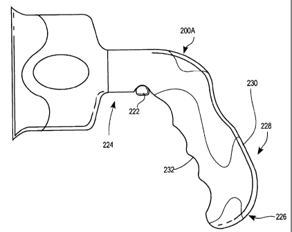
As can be seen in Fig. 12, an alternative embodiment of paint brush handle
200A is disclosed. According to this embodiment, a button 222 can be
positioned on a
lower portion 224 of neck 202. The butt end 226 of paint brush handle 200 is
formed
to have a rounded portion 228 that also may have a grip surface 230 that
extends from
the finger groove portion 232. Although not shown, paint brush handle 200 of
Figs. 9-
11 may also be configured to have a button 222.
Fig. 13 shows a cutaway view of the paint brush handle 200A of Fig. 12. In
the cutaway view, it can be seen that engagement mechanism 234. A closer view
of
engagement mechanism 234 and the operation thereof can be seen in Figs. 14-17.
Fig. 14 illustrates the various components of engagement mechanism 234.
According to the illustrated embodiment, paint brush head 204 (although other
paint
brush heads are similarly constructed and can be positioned in place of head
204) has
an integral disc 236 and a plunger 238. Integral disc 236 is illustratively
formed
integrally with paint brush head 204. In the illustrated embodiment, plunger
238 is
also formed integrally with paint brush head 204 and integral disc 236.
Plunger 238
defines a longitudinal axis.
Engagement mechanism 234 also includes a carriage 240 that is configured to
slide in a substantially coaxial direction along the longitudinal axis of
plunger 238.
Carriage 240 includes tabs 242, 244 that extend longitudinally toward brush
head 204.
On the opposite end 246 of carriage 240, carriage 240 is connected to first
lock 248,
which is in turn engaged with second lock 250. Illustratively, first and
second locks
248, 250 have teeth 252, 254 formed thereon, such that teeth 252, 254 can be
positioned to engage each other as shown in Figs. 14-15, thereby substantially
CA 02678039 2011-11-04
WO 2009/055198 PCT/US2008/078045
-9-
preventing rotary motion of carriage 240 and first lock 248 relative to second
lock
250. Second lock 250 is positioned in a fixed relationship with housing
component
256. A foot 258 also extends downwardly from second lock 250 to further secure
it in
housing component 256.
Fig. 16 shows a cutaway view of engagement mechanism 234, wherein paint
brush head 204 has been pulled outwardly in the direction shown by arrows 259.
Because plunger 238 is connected to paint brush head 204, and likewise
carriage 240
is engaged with plunger 238, carriage 240 has also moved in the direction of
arrows
259. Likewise, since first lock 248 is engaged with carriage 240, it has also
moved
with carriage 240 away from second lock 250. Accordingly, when a user pulls
paint
brush head 204 in the manner shown in Fig. 16, it causes first lock 248 to
separate
from second lock 250. The separation of first and second locks 248 and 250
permits
first lock 248 to rotate relative to second lock 250. This rotation allows a
user to
reposition paint brush head 204 in an angle of rotation appropriate for the
application
or user. Once the desired angle of rotation is achieved, the user can release
paint brush
head so that first lock 248 returns to engagement with second lock 250. Spring
260
biases carriage 240 such that it causes first lock 248 to engage second lock
250 absent
action from a user.
As can be seen in Figs. 17-18, plunger 238 engages with carriage 240 in
substantially the following fashion. A user inserts plunger 238 (which is
attached to
paint brush head 204) into chamber 262. Plunger is guided toward carriage 240
by the
walls of chamber 262.
A catch 264 is formed at the distal end 266 of plunger 238. Catch 264
functions to engage retainer 268, which is illustratively formed integrally
with slider
270. Slider 270 is illustratively housed within plunger 238 and is configured
to move
orthogonally relative to the plunger axis, in the direction indicated by arrow
272.
Slider 270 is in communication with button 222 on one end, and is biased by
spring
274 on the other end. When button 222 is depressed in the direction shown by
arrow
276 (visible in Fig. 18), internal face 278 of button 222 pushes against
slider 270,
urging it toward spring 274 and eventually causing spring 274 to compress, as
shown
in Fig. 18. Such movement of slider 270 causes retainer 268 to move upwardly
in the
direction shown by arrows 280 (Fig. 18), thereby disengaging retainer 268 from
catch
CA 02678039 2009-08-11
WO 2009/055198 PCT/US2008/078045
-10-
264 of plunger 238. In this disengaged position, shown in Fig. 18, plunger 238
can be
withdrawn from chamber 262. Such a withdrawal may be appropriate if, for
example,
a user wants to remove paint brush head 204 and exchange it for another, or
clean or
dispose of paint brush head 204.
While the disclosure is susceptible to various modifications and alternative
forms, specific exemplary embodiments thereof have been shown by way of
example
in the drawings and have herein been described in detail. It should be
understood,
however, that there is no intent to limit the disclosure to the particular
forms
disclosed, but on the contrary, the intention is to cover all modifications,
equivalents,
and alternatives falling within the spirit and scope of the disclosure.
There is a plurality of advantages of the present invention arising from the
various features of the paint brush described herein. It will be noted that
alternative
embodiments of the paint brush of the present invention may not include all of
the
features described yet still benefit from at least some of the advantages of
such
features. Those of ordinary skill in the art may readily devise their own
implementations of a paint brush that incorporate one or more of the features
of the
present invention.