Note: Descriptions are shown in the official language in which they were submitted.
CA 02678076 2009-08-13
WO 2008/106292 PCT/US2008/053441
MOTOR ASSEMBLY FOR A POWERED SURGICAL INSTRUMENT
FIELD OF THE INVENTION
The present disclosure generally relates to surgical instruments and in
particular to
surgical instruments for dissecting bone and other tissue.
BACKGROUND
Motorized surgical instruments may use a variety of methods to power moving
components. For example, a motorized surgical instrument used for dissecting
bone or
tissue may use a pneumatic motor to power a dissecting tool. Pressurized fluid
powers the
motor, which may be mechanically linked to the dissecting tool by means of a
rotatable
shaft. The application of pressurized fluid to the motor results in rotation
of the shaft,
which in turn rotates the dissecting tool.
Difficulties may arise in the assembly and operation of pneumatic surgical
instruments. Conventional pneumatic surgical instruments house the rotatable
shaft in a
rotor housing chamber defined by a rotor housing. In order to allow the shaft
to rotate
freely in the rotor housing chamber, a plurality of components are coupled to
the rotor
housing such as, for example, bearings, bearing housings, fluid distributors,
and a variety
of other components known in the art. In addition, in order to ensure that
these
components are properly positioned in the assembly, an alignment pin may be
used to
align the components with the rotor housing and the shaft. As the number of
components
coupled to the rotor housing grows, the tolerance between the components and
the rotor
housing make the repeatability of the assembly of the surgical instrument
itself difficult.
Therefore, what is needed is an improved assembly for a surgical instrument.
SUMMARY
The present disclosure provides many technological advances that can be used,
either alone or in combination, to provide an improved motor assembly for a
powered
surgical instrument and/or an improved system and method for using powered
surgical
instruments.
In one embodiment, a housing member for a powered surgical instrument
comprises a
one-piece base, a rotor housing chamber defined by the base, a first bearing
housing
CA 02678076 2014-08-22
53591-7
2
defined by the base and located adjacent the rotor housing chamber, a second
bearing housing
defined by the base and located on an opposite side of the rotor housing
chamber from the
first bearing housing, and a passage defined by the base and operable to
direct a pressurized
fluid through the base to the rotor housing chamber.
In another embodiment, there is provided an assembly for a motorized surgical
instrument, the assembly comprising: a one-piece base; a rotor housing chamber
defined by
the base; a first bearing housing defined by the base and located adjacent the
rotor housing
chamber; a passage defined by the base and operable to direct a pressurized
fluid through the
base to the rotor housing chamber; a first bearing located in the first
bearing housing; and a
rotatable shaft located in the rotor housing chamber and engaging the first
bearing.
In a further embodiment, there is provided a method for powering a surgical
instrument, the method comprising: providing a surgical instrument assembly
comprising a
one-piece base defining a rotor housing chamber, a first bearing housing
adjacent the rotor
housing chamber, and a passage coupled to the rotor housing chamber, the
surgical instrument
further comprising a rotatable shaft located in the rotor housing chamber and
engaging a first
bearing located in the first bearing housing; coupling a pressurized fluid
source to the one-
piece base; and providing high pressure fluid from the pressurized fluid
source through the
passage to rotate the rotatable shaft in the rotor housing chamber.
Further forms and embodiments will become apparent from the detailed
description provided hereinafter. It should be understood that the detailed
description and
specific examples, while indicating preferred embodiments, are intended for
purposes of
illustration only and are not intended to be limiting.
BRIEF DESCRIPTION OF THE DRAWINGS
The present disclosure will become more fully understood from the detailed
description and the accompany drawings, wherein:
CA 02678076 2014-08-22
=
53591-7
2a
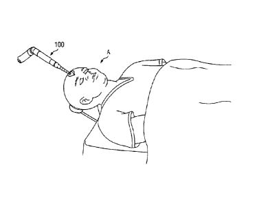
Fig. 1 is an environmental view illustrating an embodiment of a surgical
instrument for the dissection of bone and other tissue according to the
teachings of an
embodiment of the present disclosure operatively associated with a patient for
performing a
craniotomy.
Fig. 2 is a perspective view illustrating an embodiment of the surgical
instrument for the dissection of bone and other tissue according to the
teachings of an
embodiment of the present disclosure, the surgical instrument shown
operatively associated
with a hose assembly.
Fig. 3a is an exploded perspective view illustrating an embodiment of a
portion
of the surgical instrument of Fig. 2.
Fig. 3b is a perspective view illustrating an embodiment of a housing member
used in the surgical instrument of Fig. 2 and illustrated in Fig. 3a.
Fig. 3c is a side view illustrating an embodiment of the housing member
illustrated in Fig. 3b.
Fig. 3d is a cross sectional view illustrating an embodiment of the housing
member illustrated in Fig. 3b taken along the line 3d-3d in Fig. 3b.
Fig. 3e is a cross sectional view illustrating an embodiment of the remaining
portion of the housing member illustrated in Fig. 3b and not shown in Fig. 3d.
Fig. 3f is a cross sectional view illustrating an embodiment of the rotor
housing
illustrated in Fig. 3b taken along line 3f-3f in Fig. 3c.
CA 02678076 2009-08-13
WO 2008/106292 PCT/US2008/053441
3
Fig. 3g is a partial cross-sectional view illustrating an embodiment of a
portion of
the assembled surgical instrument illustrated in Fig. 3a.
Fig. 4 is a partial cross sectional view illustrating an embodiment of a
portion of
the surgical instrument illustrated in Fig. 2.
Fig. 5 is a perspective view illustrating an alternative embodiment of a
housing
member.
DETAILED DESCRIPTION
The present disclosure relates to surgical tools, and more particularly, to a
housing
member and motor assembly for use in powered surgical instruments. It is
understood,
however, that the following disclosure provides many different embodiments, or
examples, for implementing different features of the invention. Specific
examples of
components and arrangements are described below to simplify the present
disclosure.
These are, of course, merely examples and are not intended to be limiting. In
addition, the
present disclosure may repeat reference numerals and/or letters in the various
examples.
This repetition is for the purpose of simplicity and clarity and does not in
itself dictate a
relationship between the various embodiments and/or configurations discussed.
Referring initially to Fig. 1, a surgical instrument for the dissection of
bone and other
tissue constructed in accordance with the teachings of a first preferred
embodiment of the
present invention is illustrated and generally identified at reference numeral
100. The
surgical instrument 100 is shown operatively associated with a patient A for
performing a
craniotomy. It will become apparent to those skilled in the art that the
subject invention is
not limited to any particular surgical application but has utility for various
applications in
which it is desired to dissect bone or other tissue.
With reference to Fig. 2, the surgical instrument 100 is illustrated to
generally
include a motor assembly 102, an attachment 104 coupled to the motor assembly
102, and
a surgical tool 106 coupled to the attachment 104 and the motor assembly 102.
In the
preferred embodiment, the surgical tool 106 is a cutting tool or dissection
tool, although
the type of tool is not essential to implementing the present invention. A
distal end of the
dissection tool 106 includes an element adapted for a particular procedure,
such as a
cutting element. The attachment 104 may provide a gripping surface for use by
a surgeon
and may also shield underlying portions of the instrument 100 during a
surgical procedure.
CA 02678076 2009-08-13
WO 2008/106292 PCT/US2008/053441
4
The surgical instrument 100 is shown connected to a hose assembly 108 for
providing a
source of pressurized fluid (e.g., air or nitrogen) to the motor assembly 102
through a tube
110 and a passageway 112 in the hose assembly 108 for exhausting fluid after
passing
through the motor assembly 102. Typically, the hose assembly 108 is connected
to a filter
system (not shown) spaced from the patient and the exhaust fluid is allowed to
exit the
system after passing through the filter system. In the exemplary embodiments
that will be
described, the surgical instrument 100 is pneumatically powered. It is further
understood,
however, that many of the teachings discussed herein will have equal
application for
surgical instruments using other sources of power.
Referring now to Fig. 3a, one embodiment of the motor assembly 102 of Fig. 2
is
shown in detail. The motor assembly 102 includes a motor housing 200 having an
internal
surface 202 defining a generally cylindrical internal chamber 204. The motor
housing 200
may include, for example, internal shoulders (not shown) extending into the
internal
chamber 204 and seals (not shown) for creating a seal between the motor
housing 200 and
the other components of the motor assembly 102, described in further detail
below. The
seals may be made from a material comprising a compounded form of PTFE
fluorocarbons and other inert ingredients, such as the product RULON-J. This
material
provides the seals with a relatively low coefficient of friction while
requiring little or no
lubrication.
The motor assembly 102 further includes a bearing retainer member 300 having a
bearing
engagement surface 300a, a fastener 302 including a coupling member 302a, a
first
bearing 304 defining a first bearing aperture 304a, a plug 306, a rotatable
shaft 308
including a plurality of vanes 308a extending along its length and a pair of
opposing
coupling ends 308b and 308c, a bearing plate 310 defining a bearing plate
aperture 310a,
and a second bearing 312 defining a second bearing aperture 312a, all located
in and/or
coupled to a housing member 400 in a manner described in further detail below
Referring now to Figs. 3a, 3b, 3c, 3d, 3e, and 3f, the housing member 400
includes
an elongated and generally cylindrically shaped one-piece base 402 having a
first end
402a and a second end 402b located opposite the first end 402a. In the
illustrated
embodiment, housing member 400 is a unitary piece of material with various
features,
described below, defined either in or into the material. Although a unitary,
homogenous
material is shown forming housing member 400, it is contemplated that non-
homogenous
CA 02678076 2009-08-13
WO 2008/106292 PCT/US2008/053441
materials such as, for example, a substrate material coated with a different
material, may
be joined to form the one-piece housing member 400. In an embodiment, the
housing
member 400 is fabricated from stainless steel. In an embodiment, the housing
member
400 may be fabricated from ceramic and/or may include a coating in order to
make the
housing member 400 more resistant to abrasive wear. In an embodiment, the
housing
member is machined. A pressurized fluid inlet 404 is defined by the base 402
and extends
from the first end 402a of the base 402 along a longitudinal axis B of the
base 402 towards
the second end 402b of the base 402. A first bearing housing 406 is defined by
the base
402 and is located immediately adjacent the pressurized fluid inlet 404. A
coupling
aperture 408 is defined by the base 402 by an internal flange 410 that is
located
immediately adjacent the first bearing housing 406. A rotor housing chamber
412 is
defined by the base 402 and located immediately adjacent the internal flange
410 and the
coupling aperture 408 opposite the first bearing housing 406. A second bearing
housing
414 is defined by the base 402 and extends between a plate engagement wall
414a
adjacent the rotor housing chamber 412 and the second end 402b of the base
402. A
passage 416 is defined by the base 402 and extends in a substantially parallel
orientation
but radially spaced apart from the longitudinal axis B of the base 402 from a
passage
entrance 416a such that the passage 416 is axially co-located adjacent the
pressurized fluid
inlet 404, the first bearing housing 406, the internal flange 410, and a
portion of the rotor
housing chamber 412. A passage entrance 418 is defined by the base 402
oriented at an
angle to the passage 416 and provides a fluid passageway between the
pressurized fluid
inlet 404 and the passage 416. In the illustrated embodiment, the passage
entrance 418 is
oriented at a 45 degree angle to the passage 416. A plurality of rotor housing
high
pressure fluid entrances 420 are defined by the base 402 and provide a fluid
passageway
between the high pressure passage 416 and the rotor housing chamber 412. A
plurality of
rotor housing fluid exits 422 are defined by the base 402 and provide a fluid
passageway
between the rotor housing chamber 412 and outside of the base 402.
Referring now particularly to Figs. 3a and 3g, in an assembled form, the
plurality
of vanes 308a are attached to the rotatable shaft 308, which is positioned
within the rotor
housing chamber 412 of the base 402. The coupling end 308b of the rotatable
shaft 308
extends through the coupling aperture 408 and into the first bearing housing
406, and the
coupling end 308c of the rotatable shaft 308 extends through the second
bearing housing
CA 02678076 2009-08-13
WO 2008/106292 PCT/US2008/053441
6
414 and out past the second end 402b of the base 402. The bearing plate 310 is
located in
the second bearing housing 414 and in engagement with the plate engagement
wall 414a
such that the rotatable shaft 308 extends through the bearing plate aperture
310a defined
by the bearing plate 310. The second bearing 312 is located in the second
bearing housing
414 and in engagement with the bearing plate 310 such that the rotatable shaft
308 extends
through the second bearing aperture 312a and is rotatably supported by the
second bearing
312. In the illustrated embodiment, the second bearing 312 is maintained in
position by a
frictional engagement or interference fit with the internal wall of the
bearing housing 414.
In an alternative embodiment, adhesives may be used to maintain the second
bearing 312
in position.
The first bearing 304 is located in the first bearing housing 406 and in
engagement
with the internal flange 410 such that the coupling end 308b of the rotatable
shaft 308
extends into the first bearing aperture 304a and is rotatably supported by the
first bearing
304. The coupling member 302a on the fastener 302 engages the coupling end
308b on
the rotatable shaft 308 and the fastener 302 engages the first bearing 304.
The bearing
retainer member 300 is located partially in the first bearing housing 406 and
the
pressurized fluid inlet 404 such that the bearing engagement surface 300a
engages the first
bearing 304. The plug 306 is located in the passage opening 416a such that
pressurized
fluid in the passage 416 may not escape the passage 416 through the passage
opening
416a. In the illustrated embodiment, the passage opening 416a is a result of
the
fabrication of the passage 416, which requires the passage 416 be drilled into
the base 402
from the first end 402a of the housing member 402. The plug 306 is then press
fit
permanently into the passage opening 416a in order to prevent pressurized
fluid from
escaping from the passage 416 through the passage opening 416a. However,
alternative
embodiments may include fabrication techniques for the passage 416 that
eliminate the
passage opening 416a and the need for the plug 306, such as the alternative
embodiment
500 described below and illustrated in Fig. 5. In a further embodiment,
additional seals
may be provided in the housing member 400 such that a fluid tight passageway
is
provided between the first bearing housing 406, the rotor housing chamber 412,
and the
second bearing housing 414 and pressurized fluid introduced into the passage
416 flows
through the rotor housing fluid entrances 420, into the rotor housing chamber
412, and out
CA 02678076 2009-08-13
WO 2008/106292 PCT/US2008/053441
7
of the rotor housing fluid exits 422 and does not escape through the first
bearing housing
406 or the second bearing housing 414.
With continued reference to Figs. 3a and 3g, and with additional reference to
Fig.
4, in operation, the housing member 400 including the bearing retainer member
300, the
fastener 302, the first bearing 304, the plug 306, the rotatable shaft 308,
the bearing plate
310, and the second bearing 312, is positioned in the internal chamber 204 in
the motor
housing 200. In the illustrated embodiment, the engagement between the housing
member
400 and the motor housing 200 allows exhaust pressure to surround the housing
member
400 such that a majority of the exhaust pressure flows into the hose assembly
108 and
through the passageway 112. In another embodiment, the engagement between the
housing member 400 and the motor housing 200 creates a fluid tight seal. In a
further
embodiment, fluid tight seals are provided between the housing member 400 and
the
motor housing 200. The hose assembly 108 is then coupled to the motor housing
200 such
that the tube 110 is coupled to the first end 402a of the housing member 402
and provides
a sealed passageway for pressurized fluid between the tube 110 and the
pressurized fluid
inlet 404. A seal is also provided between the hose assembly 108 and the motor
housing
200. The coupling end 308c of the rotatable shaft 308 may be coupled to the
surgical tool
106 (not shown) using, for example, a collet.
Pressurized fluid in the range of 0 to 150 PSI then enters the pressurized
fluid inlet
404 from the tube 110 in the hose assembly 108, and a control may be provided
to allow a
user of the surgical instrument 100 to adjust the pressure of the pressurized
fluid between
this range. In an embodiment, the pressure of the pressurized fluid upstream
of the motor
assembly is set at 120 PSI. In an embodiment, the pressure of the pressurized
fluid
upstream of the motor assembly is set at 100 PSI. In an embodiment, pressure
losses in
the pressurized fluid upstream of the motor assembly may be between 10 to 30
PSI. The
pressurized fluid is directed into the passage 416 through the passage
entrance 418 due to
the seal between the bearing retaining member 300 and the first bearing 304
and the seal
between the plug 306 and the passage opening 416a. The pressurized fluid is
then
directed into the rotor housing chamber 412 through the rotor housing fluid
entrances 420.
As the pressurized fluid moves through the rotor housing chamber 412 from the
rotor
housing fluid entrances 420 towards rotor housing fluid exits 422, the fluid
impacts the
vanes 308a and causes rotation of the rototable shaft 308. In an embodiment,
the
CA 02678076 2009-08-13
WO 2008/106292 PCT/US2008/053441
8
centerline of the rotatable shaft 308 may be offset from the centerline of the
rotor housing
chamber 412 in order to create increased torque relative to when the
centerlines of the
rotatable shaft 308 and the rotor housing chamber 412 are co-linear. The lower
pressure
fluid then exits the rotor housing chamber 412 through the rotor housing fluid
exits 422
and travels back through the exhaust fluid passageway 112 in the hose assembly
108
between the tube 110 and the hose assembly 108. In an embodiment, the fluid
loses
pressure due to expansion and energy exchange and may be, for example, between
20-30
PSI dynamic when the pressure of the fluid upstream of the motor assembly 102
is 120
PSI. Thus, a surgical instrument is provided that includes a housing member
that allows
for a simplified assembly of the motor assembly relative to a convention rotor
housing and
decreases the passageways available to provide a fluid leak by reducing the
number of
components used in the motor assembly. While the surgical instrument 100 has
been
described as being powered pneumatically by a gas fluid, other powering
schemes are
contemplated such as, for example, hydraulically powering the surgical
instrument with a
liquid fluid.
Referring now to Fig. 5, in an alternative embodiment, a housing member 500 is
substantially similar in design and operation to the housing member 400,
described above
with reference to Figs. 3a, 3b, 3c, 3d, 3e, 3f, 3g, and 4, with the provision
of an opening
502 defined by the base 402 of the housing member 500 that is located adjacent
the
passage 416. A seal groove 504 is defined by the base 402 and is located about
the
perimeter of the opening 502. A seal groove 506 is defined by the base 402 and
is located
about the circumference of the base 402 and between the opening 502 and the
second end
402b of the base 402. In assembly, the housing member 500 is positioned in the
internal
chamber 204 of the motor housing 200 in substantially the same manner as
described
above for the housing member 400, with the provision of seals (not shown)
located in the
seal grooves 504 and 506 such that the seals engage the internal surface 202
of the motor
housing 200 and provide a fluid tight seal between the housing member 500 and
the motor
housing 200. In operation, the housing member 500 operates substantially
similarly to the
housing member 400, with the seals in the seal grooves 504 and 506 directing
pressurized
fluid through the passage 416 and into the rotor housing high pressure fluid
entrances 420.
Provision of the opening 502 provides a larger volume for the pressurized
fluid to travel
through the housing member 500 relative to the housing member 400 and reduces
the
CA 02678076 2014-08-22
,
53591-7
9
pressure drop experienced by the pressurized fluid when it travels through the
passage 416 of
the housing member 500 relative to the housing member 400. Furthermore, the
opening 502
allows fabrication of the passage 416 without the need to fabricate the
passage opening 416a
and eliminates the need for the plug 306.
While the invention has been particularly shown and described with reference
to the preferred embodiment thereof, it will be understood by those skilled in
the art that
various changes in form and detail may be made therein without departing from
the scope of
the invention. Furthermore, the housings and/or components may be replaced by
other
suitable elements to achieve similar results. In addition, a variety of
materials may be used to
form the various components and the relative sizes of components may be
varied. Therefore,
the claims should be interpreted in a broad manner, consistent with the
present invention.