Note: Descriptions are shown in the official language in which they were submitted.
CA 02678211 2009-09-11
SPECIFICATION
TITLE OF THE INVENTION
OPTICAL FILM AND POLARIZING FILM USING THE SAME, AND METHOD FOR
IMPROVING VIEW ANGLE OF THE POLARIZING FILM
This application is a division of Canadian Patent
Application No. 2,431,264 filed December 17, 2001 for Optical
FilmAnd Polarizing Film Using The Same, And Method For Improving
View Angle Of The Polarizing Film.
TECHNICAL FIELD
The present invention relates to a polarizing film and
retardation film to be used for a liquid crystal display device.
BACKGROUND ART
A polarizing film that is an essential optical member for
a liquid crystal display device is obtained by disposing, using
an adhesive, a polarizing element between protective f ilms such
as a triacetyl cellulose film whose surface layer having been
treated with an alkaline. The polarizing element is obtained,
for example, by uniaxially orienting a polyvinyl alcohol film
impregnated with a water soluble dichromatic dye or a dichromatic
pigment such as polyiodide ions in a warm aqueous boric acid
solution, by forming a polyene structure bymeans of a dehydration
reaction after uniaxially orienting a polyvinyl alcohol film.
However, when two sheets of such polarizing elements or
polarizing films are disposed so that the respective absorption
axis will be perpendicular to each other, there occurs a problem
of the light leakage, so-called the view angle dependency of
the polarizing element or polarizing film as the observation
point is tilted from the front direction to a direction different
from the direction of the respective axis because a polarized
light passed through an incident side polarizing element or
1
CA 02678211 2009-09-11
polarizing film can not be sufficiently absorbed by an emergent
side polarizing film. This phenomenon has greatly affected the
view angle characteristics of the liquid crystal display device
using various liquid crystal cells such as the vertically aligned
nematic (VA) type, in-plane switching (IPS) type and bend nematic
(OCB) type.
DISCLOSURE OF INVENTION
In intensive studies for solving the above problems, the
inventors have completed the present invention based on the novel
founding that the light leakage generated by the tilting of the
observation point from the front direction to a direction
different from the respective absorption axis direction can be
decreased, that the view angle dependency can be improved, and
that even the wavelength dependency upon improving the view angle
can be improved by means of an optical film prepared by laminating
at least one first retardation film having a mean in-plane
refractive index of no and refractive index in the thickness
direction of ne wherein ne - no > 0, and at least one second
retardation film having a refractive index of nx in the direction
exhibiting the maximum in-plane refractive index, refractive
index of nY in the direction perpendicular to the direction
mentioned just before and refractive index of nz, in the thickness
direction wherein nx > nY ? nZ, and by means of a polarizing film
prepared by laminating the optical f ilm and a polarizing element,
provided that the above polarizing film is arranged with another
polarizing element or with a polarizing f ilm having said another
2
CA 02678211 2009-09-11
polarizing element sandwiched between two protective films so
that the respective absorption axis directions will be
perpendicular to each other.
The present invention provides:
(1) An optical film prepared by laminating at least one
afirst retardation f ilm, having a mean in-plane ref ractive index
of no and a refractive index of ne in the thickness direction
wherein ne - no > 0, and at least one of a second retardation
film having an in-plane refractive index of nX in the direction
showing a maximum refractive index, a refractive index of ny
in the direction perpendicular to the direction described just
before, and a refractive index of nZ in the thickness direction
wherein nx > ny _ nZ;
(2) an optical film prepared by laminating at least one
a f irst retardation f ilm, having a mean in-plane refractiveindex
of no and a refractive index in the thickness direction of ne
in the thickness direction wherein ne - no > 0, and at least
one of an achromatic second retardation film;
(3) the optical film according to (2), wherein the
achromatic second retardation film has an in-plane refractive
index of nX in the direction showing the maximum refractive index,
a refractive index of ny in the direction perpendicular to the
direction described just before, and a refractive index of nz,
in the thickness direction with the provision of nX > ny ? nz,;
(4) the optical film according to any one of (1) to (3),
wherein OnP=dP is 5 to 200 nm when the thickness of the first
retardation film is represented by dp provided ne-no = Onp;
3
CA 02678211 2009-09-11
(5) the optical f i lm according to any one of (1) to (4),
wherein the first retardation film is a film comprised of a liquid
crystalline compound oriented almost homeotropic to the film
plane;
(6) the optical film according to (5) , wherein the liquid
crystalline compound is a cured material of one or a mixture
of more UV-curable liquid crystalline compounds;
,
(7) the optical film according to any one of (1) to (6)
wherein (nX-nY) = d at 550 nm is 100 to 400 nm when the thickness
of the second retardation film is represented by d;
(8) the optical film according to any one of (1) to (7),
wherein the second retardation film is a film comprising
polycarbonate as a main component;
(9) the optical film according to any one of (2) to (7),
wherein the achromatic second retardation film is a film
comprising a cellulose derivative as a main component;
(10) the optical film according to (9) wherein the optical
film is a film comprised of a cellulose derivative whose surface
layer having been treated with an alkali;
(11) the optical film according to any one of (1) to (10 ),
wherein the second retardation film comprised of a layer of a
liquid crystalline compound having an optical axis substantially
parallel to the layer plane;
(12) the optical film according to any one of (1) to (11)
prepared by laminating two of the second retardation f ilms having
equal n, ny and nZ with each other so that the directions showing
the maximum refractive index for respective films will be
4
CA 02678211 2009-09-11
perpendicular to each other;
(13) the optical film according to any one of (1) to (11)
prepared by laminating two of the second retardation f ilms having
nx, ny and nZ,at least one of them being different from the
corresponding other one so that the directions showing the
maximum refractive index will be perpendicular to each other;
(14) the optical film according to any one of (1) to (13)
prepared by laminating at least one of a third retardation film
having a mean in-plane refractive index of no and a refractive
index in the thickness direction of ne wherein ne - no < 0;
(15) the optical film according to (14), wherein jOnn=dnj
is 5 to 200nm when the thickness of the third retardation film
is represented by dn with the provision of ne-no = Onn;
(16) the optical film according to (14) or (15), wherein
the third retardation film is a triacetyl cellulose film;
(17) the optical film according to (14) to (16) prepared
by laminating two second retardation f ilms so that the directions
showing the maximum refractive index will be perpendicular to
each other, followed by sequentially laminating the first
retardation film and third retardation film;
(18) the optical film according to any one of (1) to (17),
wherein the absolute value of the difference between the sum
of 4np=dp of the first retardation film and the sum of lOnn=dpl
of the third retardation film is 5 to 100 nm;
(19) an optical film comprised of an achromatic fourth
retardation film having an in-plane refractive index of nx in
the direction showing the maximum ref ractive index, a refractive
CA 02678211 2009-09-11
index of ny in the direction perpendicular to the direction
described just before, and a refractive index of nZ in the
thickness direction wherein of nX > ny and nz, > ny;
(20) an optical film prepared by laminating a third
retardation film having a mean in-plane refractive index of no
and a refractive index of in the thickness direction ne wherein
ne - no < 0, and an achromatic fourth retardation film having
an in-plane refractive index nX in the direction showing the
maximum refractive index, a refractive index of nY in the
direction perpendicular to the direction described just before,
and a refractive index of nz in the thickness direction wherein
nx > ny and nZ > ny;
(21) the optical film according to (19) or (20), wherein
Ona = da of the fourth retardation film at 550 nm is 100 to 400
nm when the thickness of the film is represented by da wherein
nX - ny = Ana;
(22) a polarizing film comprising the optical film
according to any one of (1) to (21) and a polarizing element;
(23) the polarizing film according to (22) prepared by
laminating the second retardation film or fourth retardation
film so that the direction showing the maximum refractive index
either of the second retardation film or fourth retardation film
to be disposed at the polarizing element (17) side will align
with the direction of the absorption axis of the polarizing
element;
(24) a method for improving the view angle of a polarizing
element, wherein the optical film according to (1) to (21) is
6
CA 02678211 2009-09-11
sandwiched between two the polarizing elements (17) disposed
so that their absorption axis will be perpendicular to each other;
(25) a method for improving the view angle of a polarizing
element, wherein the polarizing film according to any one of
(22) and (23) is used as one of the two sheets of the polarizing
element, and the absorption axis of the polarizing element is
rendered perpendicular to the absorption axis of the other
polarizing element;
(26) a method for improving the view angle of a polarizing
element, wherein the polarizing film according to any one of
(22) and (23) is used for one of the two of the polarizing element,
and a polarizing film sandwiched between two of the third
retardation film having a mean in-plane refractive index no and
a refractive index in the thickness direction of ne with the
provision ne - no < 0 is used for the other polarizing element,
and wherein the each absorption axis (24) of the polarizing
elements is rendered perpendicular to each other;
(27) the method for improving the view angle of a polarizing
element according to any one of (24) to (26) , wherein the absolute
value of the difference between the sum of I Onn= dn I of the third
retardation f ilm sandwiched between the polarizing elements and
the sum of Onp = dp of the first retardation film sandwiched between
the polarizing elements is 5 to 100 nm;
(28) a liquid crystal display device comprising the optical
film or polarizing film according to any one of (1) to (23);
(29) the liquid crystal display device according to (28),
wherein a liquid crystalcellforeffectingimage display device
7
CA 02678211 2009-09-11
is sandwiched between arbitrary films among respective films
constituting the optical film according to any one of (1) to
(21) disposed between the polarizing elements disposed so that
the absorption axis will be perpendicular to each other;
(30) the liquid crystal display device according to (28),
wherein a liquid crystal cell is sandwiched between the
polarizing film sandwiched between two of the third retardation
film having a mean in-plane refractive index no and refractive
index in the thickness direction of ne wherein ne - no < 0, and
the polarizing film according to any one of (22) and (23);
(31) the liquid crystal display device according to (28),
wherein the liquid crystal cell is sandwiched between two of
the second retardation films constituting the polarizing film
according to any one of (22) and (23), and at the same time the
polarizing elements are provided each side of the second
retardation f ilms opposed to the cell, those f ilm being laminated
so that the direction showing the maximum refractive index of
each second retardation film will align with the direction of
the absorption axis of the polarizing element at each side;
(32) the liquid crystal display device according to any
one of (28) to (31) wherein the liquid crystal cell is a liquid
crystal cell that has improved its own view angle dependency.
BRIEF DESCRIPTION OF THE DRAWINGS
FIG. 1 shows a retardation film;
FIG. 2 is a graph showing the change of the retardation
value of conventional polycarbonate retardation film depending
8
CA 02678211 2009-09-11
on the wavelength;
FIG. 3 is a graph showing the change of the retardation
value of an ideal achromatic retardation film depending on the
wavelength;
FIG. 4 shows an embodiment of the optical film of the
inclination;
FIG. 5 shows an embodiment of lamination of the second
retardation film to be used for the optical film according to
the invention;
FIG. 6 shows another embodiment of the optical film
according to the invention;
FIG. 7 shows another embodiment of lamination of the second
retardation film to be used for the optical film according to
the invention;
FIG. 8 shows a different embodiment of the optical film
according to the invention;
FIG. 9 shows a further different embodiment of the optical
film according to the invention;
FIG. 10 shows a further different embodiment of the optical
film according to the invention;
FIG. 11 shows a further different embodiment of the optical
film according to the invention;
FIG. 12 shows a further different embodiment of the optical
film according to the invention;
FIG. 13 shows a further different embodiment of the optical
film according to the invention;
FIG. 14 shows a further different embodiment of the optical
9
CA 02678211 2009-09-11
film according to the invention;
FIG. 15 shows an embodiment of the polarizing film
according to the invention;
FIG. 16 shows another embodiment of the polarizing film
according to the invention;
FIG. 17 shows a different embodiment of the polarizing
film according to the invention;
FIG. 18 shows a further different embodiment of the
polarizing film according to the invention;
FIG. 19 shows a construction of the polarizing film
according to the invention;
FIG. 20 shows another construction of the polarizing film
according to the invention;
FIG. 21 shows a different construction of the polarizing
film according to the invention;
FIG. 22 shows an embodiment of the method for improving
the view angle of the polarizing film according to the invention;
FIG. 23 shows a construction in the method for improving
the view angle of the polarizing film according to the invention;
FIG. 24 shows a different embodiment of the method for
improving the view angle of the polarizing film according to
the invention;
FIG. 25 shows another construction in the method for
improving the view angle of the polarizing film according to
the invention;
FIG. 26 is a drawing concerning the view angle dependency
of the polarizing film;
CA 02678211 2009-09-11
FIG. 27 shows a further different embodiment of the method
for improving the view angle of the polarizing film according
to the invention;
FIG. 28 shows a different construction in the method for
improving the view angle of the polarizing film according to
the invention;
FIG. 29 shows a further different embodiment of the method
for improving the view angle of the polarizing film according
to the invention;
FIG. 30 shows a further different construction in the
method for improving the view angle of the polarizing film
according to the invention;
FIG. 31 shows a further different construction in the
method for improving the view angle of the polarizing film
according to the invention;
FIG. 32 shows a different construction of the polarizing
film according to the invention;
FIG. 33 shows a further different construction of the
polarizing film according to the invention;
FIG. 34 shows an embodiment of the liquid crystal display
device according to the invention in which the view angle
characteristics are improved;
FIG. 35 shows a construction of the liquid crystal display
device in which the view angle characteristics are improved;
FIG. 36 shows another construction of the liquid crystal
display device in which the view angle characteristics are
improved;
11
CA 02678211 2009-09-11
FIG. 37 shows another embodiment of the liquid crystal
display device in which the view angle characteristics are
improved;
FIG. 38 shows a different construction of the liquid
crystal display device in which the view angle characteristics
are improved;
FIG. 39 shows a different construction of the liquid
crystal display device in which the view angle characteristics
are improved;
FIG. 40 is a graph showing the change of the retardation
value against the inclination of the first retardation film
described in Example 1 used in the invention;
FIG. 41 shows a construction of the liquid crystal display
device according to the invention described in Examples 4;
FIG. 42 is a graph showing the change of the retardation
value against the inclination of the first retardation film
described in Example 5 used in the invention;
FIG. 43 is a graph showing the change of retardation value
of the second retardation film to be used in Example 5 depending
on the wavelength;
FIG. 44 shows the liquid crystal display device described
in Comparative Example 3; and
FIG. 45 is a graph showing transmittance against the
wavelength measured in Examples and Comparative Examples of an
incident light with the inclination of 50 at 45 direction from
each absorption axis when the respective absorption axes are
perpendicular to each other.
12
CA 02678211 2009-09-11
BEST MODE FOR CARRYING OUT THE INVENTION
The invention will be described in more detail with
reference to attached drawings.
The optical film according to the invention comprises a
laminate of a plurality of retardation films. In a first
retardation film to be used in the invention, an in-plane mean
refractive index no determined by the following equation (1)
and a refractive index ne in the thickness direction determined
by the following equation (2) satisfy a relation of ne - no >
0, wherein the refractive index in the direction showing the
maximum in-plane refractive index is represented by nX, and the
refractive index perpendicular to the above direction is
represented by ny as shown in FIG. 1.
no = (nX + nY) /2 (1)
ne = nZ (2)
The smaller is preferable the difference between nx and ny, and
they are more preferably equal with each other. Preferably,
dp and Onp of the film are adjusted so that Onp=dp as a product
thereof is adjusted so that it is preferably 5 to 200 nm, more
preferably 10 to 100 nm and particularly 20 to 60 nm, wherein
the thickness of the film is represented by dp, and Anp is defined
by ne - no. While examples of such retardation films include
polycarbonate, polyethylene terephthalate, polyether sulfone,
polyethylene, a cycloolefin polymer such as norbornene
derivatives, or a plastic film mainly comprising triacetyl
cellulose, diacetyl cellulose, polyolefin, polyethylene and
13
CA 02678211 2009-09-11
polyvinyl alcohol, which are biaxially stretched in the nX and
ny directions followed by stretching in the nZ direction, or
afilm comprising a liquid crystalline compound homeotropically
aligned to the film plane. However, it is particularly
preferable to use the film comprising the liquid crystalline
compound homeotropically aligned the film plane, since nX and
nY becomes substantially equal with each other.
Examples of the liquid crystalline compound that is
homeotropically aligned perpendicular to the plane of the film
to be used for the first retardation film of the invention include
a thermotropic liquid crystalline compound that exhibits
crystallinity in a certain temperature range, and a lyotropic
liquid crystalline compound that exhibits a liquid crystalline
property in a particular concentration range. A plurality of
liquid crystalline compounds are mixed in order to permit the
thermotropic liquid crystalline compound to exhibit
crystallinity in a wide temperature range. The liquid
crystalline compounds may be a low molecular weight compound,
a high molecular weight compound or a mixture thereof. These
liquid crystalline compounds are preferably polymerized or
cross-linked by UV light or heat in order to fix the oriented
state. The liquid crystalline compound preferably has
polymerizable groups such as (meth)acryloyl, epoxy and vinyl
groups, or has cross-linkable functional groups such as amino
and hydroxyl groups. Examples of such compounds are described
inWO 97/44703 andWO 98/00475. These compounds include a liquid
crystalline compound that is horizontally oriented (in-plane
14
CA 02678211 2009-09-11
orientation) with a slightly tilted angle at the alignment layer
side when the layer of the compound is formed on a substrate
subjected to a rubbing treatment such as a conventional polyimide
alignment layer that is used for producing a twisted nematic
(TN) liquid crystal cell, and is almost homeotropically aligned
at the air interface side (homeotropic liquid crystalline
compound); or a liquid crystalline compound that is
homeotropically aligned when the layer of the compound is formed
on a substrate that allows the compound to be almost
homeotropically aligned, or on a glass substrate. A film
comprising a liquid crystalline compound that is readily
homeotropically aligned to the film plane can be obtained by
usingsuchliquidcrystallinecompound and by using an alignment
layer that allows the compound to be homeotropically aligned
to the film plane. When these compounds are polymerized or
cross-linked by UV light or heat in the presence of a
polymerization initiator or a cross linking agent while
maintaining the alignment state, optical anisotropic film
obtained can retain their alignment states against temperature
changes thereafter.
The method for allowing the liquid crystalline compound
to be homeotropically aligned to the f ilmplane comprises f orming
an alignment layer that allows the liquid crystalline compound
to be homeotropically aligned to a substrate film, and forming
a layer of the liquid crystalline compound on the surface of
the alignment layer. Examples of the alignment layer that
permits homeotropic alignment include a polyimide film having
CA 02678211 2009-09-11
side chains such as long chain alkyl groups; a film obtained
by cross-linkable of an acrylic polymer, which is obtained by
copolymerization of a long chain alkyl(meth)acrylate such as
n-butyl(meth)acrylate and n-hexyl(meth)acrylate with acrylic
acid or a (meth)acrylate having a functional group such as
2-hydroxyethyl(meth)acrylate, with a cross-linkable agent such
as toluene diisocyanate and 1,6-hexane diisocyanate; a
uniaxially stretched polyvinyl alcohol film treated with boric
acid; and a polyvinyl alcohol film formed on a substrate film
and treated with boric acid. These films are subjected to a
rubbing treatment.
While the layer of the liquid crystalline compound may
be formed by directly applying the compound on the alignment
layer when the compound itself is able to be applied alone for
forming the layer of the liquid crystalline compound on the
alignment layer, it is also possible to apply the compound as
a solution. The solvents for the application solution of the
compound is not particularly restricted, so long as the solution
has good wettability in applying on the alignment layer, and
orientation of the liquid crystal layer is not disturbed after
drying. While examples of the solvent include aromatic
hydrocarbons such as toluene and xylene; ethers such as anisole,
dioxane and tetrahydrofuran; ketones such as methylisopropyl
ketone, methylethyl ketone, cyclohexanone, cyclopentanone,
2-pentanone, 3-pentanone, 2-hexanone, 3-hexanone, 2-heptanone,
3-heptanone, 4-heptanone and 2,6-dimethyl-4-heptanonre;
alcohols such as n-butanol, 2-butanol, cyclohexanol and
16
CA 02678211 2009-09-11
isopropyl alcohol; cellosolves such as methyl cellosolve and
methyl cellosolve acetate; and esters such as ethyl acetate,
butyl acetate andmethyl lactate, the solvents are not restricted
thereto. The solvents may be used alone, or as a mixture thereof .
While the concentration for dissolving the liquid crystalline
compounds differs depending on the solubilizing power of the
solvent, wettability of the solvent on the substrate film and
thickness after application, it is preferably 5 to 80% by weight,
more preferably 10 to 70% by weight. It is also possible to
add various leveling agents in order to enhance wettability on
the substrate film comprising the homeotropic alignment layer
and uniformity of the application thickness. Any leveling
agents are available so long as alignment of the liquid crystal
is not disturbed.
While the method for coating the liquid crystalline
compound on the alignment layer is not particularly restricted,
the compound is preferably applied as uniform as possible since
the thickness of the liquid crystal layer after application
affects the value of OnP= dP. Examples of the application method
include a micro-photogravure coating method, photogravure
coating method, wire-bar coating method, dip coating method,
spray coating method and meniscus coating method. While the
thickness of the layer of the liquid crystalline compound differs
depending on the desired 4np=dP value as well as on the Onp value
of the oriented liquid crystalline compound, it is preferably
0.05 to 20 m, more preferably 0.1 to 10 m.
The layer of the liquid crystalline compound is formed,
17
CA 02678211 2009-09-11
for example, by the steps of: applying a solution of the liquid
crystalline compound (a polymerization initiator or
cross-linkable agent, and a leveling agent are added, if
necessary) prepared by considering solubility and wettability
on a substrate film having an alignment layer that permits
homeotropic alignment to the film plane; allowing the liquid
crystalline compound to be homeotropically aligned by heat
drying; and fixing the oriented layer by UV light or heat
polymerization or cross-linkable, if necessary. The conditions
for drying by heating, and the conditions for polymerization
or cross-linkable by UV light or heat are appropriately
determined considering the kind of the solvent used, and
temperature dependent changes and stability of alignment of the
liquid crystalline compound. The layer of the liquid
crystalline compound formed as described above may be bonded
to a second retardation film using a pressure sensitive adhesion
(PSA) after peeling the layer, or the first retardation film
may be used by being directly formed on the second retardation
film having an alignment layer as it is, as long as the substrate
film does not compromise the characteristics of the optical film
as in the case where it is, for example, the second retardation
film according to the invention.
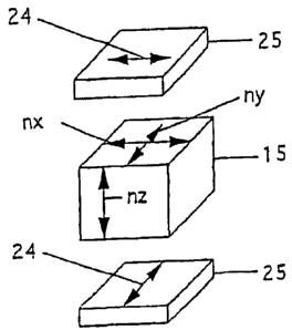
The second retardation film to be used in the invention
has a refractive index nx in the direction showing the maximum
refractive index in the film plane, a refractive index ny in
the direction perpendicular to the direction described just
before, and a refractive index nZ in the thickness direction
18
CA 02678211 2009-09-11
wherein nX > ny _ nZ as shown in FIG. 1. When the thickness of
the second retardation film is represented by d, the value of
(nx - ny) = d at 550 nm is preferably 100 to 700 nm, more preferably
100 to 300 nm, and particularly 100 to 200 nm. Examples of such
retardation film include a retardation film comprising
polycarbonate, polyethylene terephthalate, polyether sulfone,
and a cycloolefin polymer such as norbornene derivatives, a
plastic film mainly comprising triacetyl cellulose, diacetyl
cellulose, polyolefin, polyethylene or polyvinyl alcohol
prepared by uniaxially stretching, and afilm comprising a layer
of a liquid crystalline compound horizontally oriented to the
film plane. The film mainly comprising polycarbonate is
possibly used because it is excellent in durability such as
moisture and heat resistance, and is readily available since
it is widely used as an optical compensation film of super-twisted
nematic (STN) liquid crystal displays. The film mainly
comprising polyvinyl alcohol is preferable since it is possible
to allow the liquid crystalline compound to be homeotropically
aligned by treating with boric acid while being able to directly
use as the optical film of the invention. A film having a
substantially parallel optical axis in the layer plane and
comprising a layer of the liquid crystal compound aligned in
parallel to the film plane may be obtained by: applying an
alignment treatment by a rubbing treatment using the third
retardation filmto be described hereinafter as a substrate f ilm;
coating a solution of the liquid crystalline compound on the
plane after applying the orientation treatment; forming a layer
19
CA 02678211 2009-09-11
of the liquid crystalline compound by heat drying; and fixing
the alignment while the liquid crystalline compound is
horizontally aligned to the film plane. Such treatment is
preferable for producing an integrated film of the third
retardation film and second retardation film without bonding
the third retardation film and second retardation film with a
PSAor an adhesive, and for simplifying themanufacturing process
by reducing the thickness of the optical film of the invention.
The liquid crystalline compound may be a low molecular weight
compound, a high molecular weight compound or a mixture thereof,
and the compound may be polymerized or cross-linked by UV light
or heat for fixing the oriented state. Examples of such compounds
preferably include a compound having polymerizable groups such
as (meth) acryloyl groups, epoxy groups and vinyl groups, or a
compound having cross-linkablefunctional groups such as amino
groups and hydroxyl groups, and aredisclosedin Japanese Patent
Application Laying Open No. 2000-98133.
The second retardation film to be used in the invention
may be an achromatic retardation film having a refractive index
nx in the direction showing an in-plane maximum refractive index,
a refractive index nl, in the direction perpendicular to the
direction described just before, and a refractive index nZ in
the thickness direction wherein nX > nY _ nZ. The term
"achromatic" means that the retardation has'a small wavelength
dependency. As shown in FIG. 2, the retardation at a wavelength
shorter than 550 nm becomes larger than 1/4 wavelength at the
short wavelength side, while the retardation becomes smaller
CA 02678211 2009-09-11
than 1/4 wavelength at a given wavelength at the longer wavelength
side, when the retardation film gives a retardation of about
1/4 wavelength at 550 nm in the front direction of a conventional
polycarbonate film. In contrast, the retardation becomes 1/4
wavelength at an arbitrary wavelength at both wavelength side
shorter than and longer than 550 nm as shown in FIG. 3 in an
ideal achromatic retardation film, when the film gives a
retardation of 1/4 wavelength at 550 nm in the front direction
of the film. When the retardation of the achromatic retardation
film to be used in the invention is represented by nx - ny =
An and the thickness of the film is represented by d, the value
of 4n=d is 100 to 400 nm, preferably 120 to 150 nm and 240 to
300 nm at 550 nm in the front direction of the film. Thedifference
between the retardation obtained in the ideal achromatic film
(for example, a retardation film that gives a retardation of
100 nm at 400 nm, a retardation of 137.5 nm at 550 nm, and a
retardation of 200 nm at 800 nm when the retardation is 1/4 of
the wavelength) and the actually obtained retardation at a given
wavelength is preferably -50 to 50 nm, more preferably -30 to
30 nm, at a wavelength shorter than 550 nm, and preferably -80
to 80 nm, more preferably -60 to 60 nm, at a wavelength longer
than 55 nm. It is preferable to use such achromatic retardation
film in order to reduce wavelength dependency of the view angle
improving effect of the polarizing film obtained in the
invention.
The achromatic retardation film according to the invention
may be obtained by uniaxially stretching a substance having
21
CA 02678211 2009-09-11
achromatic characteristics. An example of such substance is
cellulose derivatives described in Japanese Patent Application
Laying Open No. 2000-137116. The surface of a film made of a
cellulose derivative is treated with an alkali, and a polarizing
element is preferably sandwiched between the cellulose
derivatives together with other protective films using a
polyvinyl alcohol adhesive such as an aqueous polyvinyl alcohol
solution in order to allow the polyester derivative film to also
function as a protective film of the polarizing element. The
polarizing element is obtained by uniaxially orienting a
polyvinyl alcohol film impregnated with a dichromatic pigment
such as a water soluble dichromatic dye or polyiodide ions in
a warm aqueous boric acid solution. The film may be uniaxially
oriented by uniaxial in-plane stretching of thefilm comprising
the substances as described above.
The optical film of the invention is obtained by laminating
at least one of the first retardation film and at least one of
the second retardation film. FIG. 4 shows the optical film 4
of the invention obtained by laminating the first retardation
film 2 and second retardation film 3. The retardation films
may be laminated using a PSA or an adhesive, or the first
retardation film may be directly laminated on the second
retardation film with interposition of an alingment layer. When
nx and nY of the first retardation film is not equal with each
other, the films are preferably laminated so that the nX direction
of the first retardation film aligns with the nX or ny direction.
Otherwise, the optical film of the invention 5 is obtained using
22
CA 02678211 2009-09-11
two of the second retardation films 3 having equal nX, ny and
nZwith each other by laminating these films so that the nX
directions of the two films align with each other as shown in
fig. 5, and the first retardation film 2 is laminated thereon
as shown in FIG. 6. This arrangement is more preferable for
reducing wavelength dependency of the view angleimproving effect
of the polarizing film obtained in the invention. It is
preferable in this case to laminate the retardation films so
that the nx direction of the first retardation film aligns with
the nX direction or ny direction of the second retardation film
3, when nx is not equal to ny in the first retardation film 2.
At least one of nX, ny and nZ may be different from the others
between the two of the second retardation films, when two of
the second retardation film are use. In such example, the
retardation film 6 having a refractive index nxl in the direction
showing an in-plane maximum refractive index, a refractive index
nyl in the direction perpendicular to the direction described
just before, and a refractive index nZl in the thickness direction
wherein nXl > nyl ? nz,l, and the retardation film 7 having a
refractive index nx2 in the direction showing an in-plane maximum
refractive index, a refractive index n},2 in the direction
perpendicular to the direction described just before, and a
refractive index nz2 in the thickness direction wherein nX2 >
ny2 _ nz2 are laminated so that the directions of nxl and nxz are
perpendicular to each other as shown in FIG. 7, and the first
retardation film 2 is laminated thereon to obtain the optical
film 8 of the invention as shown. in FIG. 8. It is more preferable
23
CA 02678211 2009-09-11
in this case to laminate the retardation films so that the nx
direction of the first retardation film aligns with the nXl
direction or nyl direction of the second retardation film, when
nX and ny of the first retardation film are not equal with each
other.
It is also possible in the optical film of the invention
to use at least one of the third retardation film in addition
to the first retardation film and second retardation film. In
the third retardation film to be used in the invention, the
in-plane mean refractive index no determined by the equation
(1), and the refractive index ne in the thickness direction
determined by the equation (2) satisfy the relation of ne - no
< 0. It is preferable that the difference between nX and ny is
smaller. Preferably, dn and Onn are adj usted so that the absolute
value l4nn = dn l as a product of 4nn and dn is preferably 5 to 200
nm, more preferably 10 to 150 nm and particularly 10 to 100 nm,
when the thickness of the film is represented by dõ and the
difference ne -no is represented by 4nn. Examples of such
retardation film include retardation films obtained by biaxially
stretching a triacetyl cellulose film, polycarbonate film,
polyethylene terephthalate film, polyether sulfone film,
cycloolefin polymer such as norbornene derivatives, or a plastic
film mainly comprising polyolefin, polyethylene and polyvinyl
alcohol in the nX and ny directions, and retardation films
comprising an aligned cholesteric liquid crystal. However, the
triacetyl cellulose film is particularly preferable for allowing
it to serve as both the protective film of the polarizing film
24
CA 02678211 2009-09-11
and the third retardation film to be used in the invention by
using it as an integrated film of the optical film and polarizing
film, because the triacetyl cellulose film is excellent in
transparency while being widely used as the protective film of
the polarizing element.
Examples of the optical film having the third retardation
film of the invention include an optical film 10 obtained by
laminating the first retardation film 2 laminated on the second
retardation f ilm 3 with additionally laminated third retardation
film 9 as shown in FIG. 9, and the optical films 11 and 12 in
which the order of lamination is changed as shown in Figs. 10
and 11. Other examples include an optical film 13 of the
invention obtained by laminating the third retardation film 9
on two of the second retardation films 3 laminated so that the
nx directions of the films are aligned with each other as shown
in FIG. 12, followed by laminating the first retardation film
2 thereon. It is also possible to obtain an optical film 14
of the invention by inverting the order of lamination of the
first retardation film 2 and second retardation film 9 as shown
in FIG. 13. In particular, using the third retardation film
9 as a film that also serves as the protective film of the
polarizing element as shown in FIG. 13 is preferable, since the
polarizing element can be directly sandwiched with the other
protective film at the third retardation film 9 side. The
retardation films to be used in the invention may be laminated
using a PSA or an adhesive, if necessary. Preferably, the first
retardation film 2 and third and first retardation film 9 are
CA 02678211 2009-09-11
laminated so that the nx directions of the former aligns with
the nx or ny direction of the latter, when nx and ny in the first
retardation film 2 and in the third contrast film 9 are not equal
with each other.
Desirably, 4np=dp andl4nn=dnl of each film is adjusted
so that the absolute value I (Y-Onp=dp - Y_ IOnn=dpI ) I of the
difference between the sum Y-np=dp of 4np=dp of each first
retardation f ilm constituting the opticalfilm of the invention
and the sum Z I Onn = dn I of I 4nn = dn I of the third retardation film
constituting the optical film of the invention is 5 to 100 nm,
preferably 5 to 70 nm, in order to more evidently exhibit the
view angle improving effect attained in the invention.
The fourth retardation film to be used in the invention
has achromatic characteristics as well as an in-plane refractive
index nX in the direction showing the maximum refractive index,
a refractive index ny in the direction perpendicular to the
direction described just before, and a refractive index nZ in
the thickness direction with relations of nX > nY and nZ > ny.
The retardationOna = da of the fourth retardation film to be used
in the invention is 100 to 400 nm, preferably 120 to 150 nm and
240 to 300 nm at 550 nm, in the front direction of the film,
when Ona is represented by 4na = nx - ny and the thickness of
the film is represented by da. The difference between the
retardation obtained in the ideal achromatic film as shown in
FIG. 3 (for example, a retardation film that gives a retardation
of 100 nm at 400 nm, a retardation of 137.5 nm at 550 nm, and
a retardation of 200 nm at 800 nm when the retardation is 1/4
26
CA 02678211 2009-09-11
wavelength) and the actually obtained retardation at a given
wavelength is preferably -50 to 50 nm, more preferably -30 to
30 nm, at a wavelength shorter than 550 nm, and preferably -80
to 80 nm, more preferably -60 to 60 nm, at a wavelength longer
than 55 nm.
The fourth retardation film to be used in the invention
is obtained, for example, by stretching a substance having
achromatic characteristics in both directions of the in-plane
direction and the thickness direction . Examples of such
substance include cellulose derivatives disclosed in Japanese
Patent Application Laying Open Nos. 2000-137116 and 2000-91743,
and copolymer compositions comprising norbornene chains and
styrene chains described in Japanese Patent Application Laying
Open No. 2001-135622. Thefilm made ofthe cellulose derivative
is particularly preferable since it also functions as a
protective film of a polarizing element by sandwiching the
polarizing element between the cellulose film and another
protective film using a polyvinyl alcohol adhesive such as an
aqueous solution of polyvinyl alcohol after treating the surface
layer of the polyvinyl alcohol film with an alkali. The
polarizing element is obtained by uniaxially stretching the
polyvinyl alcohol film impregnated with a dichromatic pigment
such as a water soluble dichromatic dye or polyiodide ions in
a warm aqueous boric acid solution. The film can be biaxially
oriented by stretching the both surfaces of the film comprising
the substances above in the thickness direction using a sticky
roll after uniaxially stretching in an in-plane direction;
27
CA 02678211 2009-09-11
uniaxi ally stretching the film in the in-plane direction followed
by allowing the film to orient in the thickness direction by
appropriately contracting the film in the direction opposed to
the stretching direction; and allowing the film to orient in
the thickness direction by applying an electric field or a
magnetic field in the thickness direction after uniaxial
stretching in the in-plane direction. Desirably, the degree
of orientation in the nx, nl, and nZ directions is controlled so
that the NZ coefficient represented by the following equation
(3) is preferably 0.3 to 1, more preferably 0.5 to 0.8:
NZ = (nx - nZ) / ( nX - nY) (3)
The optical film of the invention may be produced using
the fourth retardation film, or by laminating the fourth
retardation film with the third retardation film. FIG. 14 shows
an optical film 16 of the invention obtained by laminating the
fourth retardation film 15 and third retardation film 9.
The polarizing film of the invention can be obtained by
integrating the optical film produced as described above with
the polarizing film. For example, the polarizing element can
be obtained by uniaxially orienting a polyvinyl alcohol film
impregnated with a dichromatic pigment such as a dichromatic
dye or polyiodate ions in a warm aqueous boric acid solution,
or by uniaxially stretching the polyvinyl alcohol film followed
by forming a polyene structure by a dehydration reaction.
Examples of the polarizing film of the invention include the
polarizing film 19 comprising the first retardation film 2,
second retardation film 3, polarizing element 17 and protective
28
CA 02678211 2009-09-11
film 18 as shown in fig. 15; and the polarizing film 20 comprising
the first retardation film 2, second retardation film 3, third
retardation film 9, polarizing element 17 and protective film
18 as shown in FIG. 16. The protective film is preferably
excellentintransparency and adhesive propertytothepolarizing
element while having an appropriate strength, and examples of
them include a triacetyl cellulose film and a film mainly
comprising a cycloolefin polymer such as norbornene derivatives.
A function as a protective film may be obtained by forming a
resin layer having no optical anisotropy such as an acrylic resin
layer. The triacetyl cellulose film is particularly preferable,
since it is favorably used as a protective film of the polarizing
element comprising the polyvinyl alcohol film while having the
function of the third retardation filmto be used in the invention.
The surface of the triacetyl cellulose film is recommended to
be treated with an alkali before use, since the adhesive property
to the polarizing element made of the polyvinyl alcohol film
is improved by using an adhesive comprising an aqueous solution
of polyvinyl alcohol for sandwiching the polarizing element when
the surface of the triacetyl cellulose film is treated with an
alkali. FIG. 17 shows an example of the polarizing film 22 of
the invention comprising the second retardation film 3, first
retardation film 2, and the polarizing element 17 interposed
between the triacetyl cellulose f ilms 21 as the third retardation
films having the surface layers treated with an alkali. FIG.
18 shows another example of the polarizing film 23 of the invention
comprising two of the second retardation films 3 having the nx
29
CA 02678211 2009-09-11
directions perpendicular to each other, first retardation film
2, and the polarizing element 17 interposed between the triacetyl
cellulose films 21 as the third retardation films having the
surface layers treated with an alkali. It is possible to bond
the polarizing element comprising the polyvinyl alcohol film
and protective film using water, when the polarizing element
is interposed between the polyvinyl alcohol films as the
protective films having surfaces subjected to an easy-adhesion
treatment. Other adhesives or PSA may be used when the adhesive
property between the protective film and polarizing element is
insufficient using the adhesive described above.
The polarizing film of the invention is obtained by
laminating the optical film, polarizing element and protective
film. For example, as shown in FIG. 19, the polarizing film
22 of the invention as shown in FIG. 17 can be obtained by
laminating the polarizing film 25 on the optical film 4 of the
invention comprising the laminated first retardation film 2 and
retardation film 3, wherein the polarizing element 17 is
sandwiched between the third retardation f ilms, or the triacetyl
cellulose films 21 comprising surface layers treated with an
alkali, in the polarizing film 25. In another example, the
polarizing film20 as shown in FIG. 16 canbe obtainedby laminating
the first retardation film 2 on the second retardation film 3,
followed by laminating the optical film 26 having the protective
film 18 bonded only on one side of the polarizing element 17
on the optical film 10 of the invention having the laminated
third retardation film 9 as shown in FIG. 20. Each retardation
CA 02678211 2009-09-11
f ilm and the polari zing element may be laminated using an adhesive
or a PSA. As shown in Figs. 19 and 20, the films are particularly
laminated so that the direction of the absorption axis 24 of
the polarizing element aligns with the nZ direction of the second
retardation film 3. Furthermore, the first, second and third
retardation films are preferably laminated so that nx directions
thereof are aligned with each other when nX and ny in each of
the first retardation film 2 and the third retardation film are
not equal with each other in Figs. 19 and 20, while allowing
the direction of the absorption axis 24 of the polarizing element
to align with the nX direction of each film. As shown in FIG.
21, the polarizing film 23 of the invention as shown in FIG.
18 can be obtained by laminating two of the second retardation
films 3, which are laminated so that the nX directions are
perpendicular to each other, and the optical film 5 of the
invention comprising the first retardation film 2 using the
triacetyl cellulose films 21 having surface layers treated with
an alkali as the third retardation films, and using the polarizing
film 25 having the polarizing element 17 interposed between the
third retardation films. However, it is preferable to laminate
the polarizing element and the second retardation film so that
the nx direction of the second retardation film 3 at the polarizing
element 17 side aligns with the direction of the absorption axis
24 of the polarizing element 17 as shown in FIG. 21 . Furthermore,
it is more preferable to laminate the first, second and third
retardation films so that the nx directions of the first
retardation film 2 and third retardation film 21, and the nX
31
CA 02678211 2009-09-11
direction of the second retardation film 3 at the polarizing
element side are aligned with each other, and so that the nX
directions of thefirst retardation f ilm 2 and third retardation
film 21, and the nX direction of the second retardation film
3 at the polarizing element side and the direction of the
absorption axis 24 of the polarizing element are aligned with
each other, when nX and ny of each of the first retardation film
2 and the third retardation film 21 are not equal with each other.
The view angle dependency of the polarizing film can be
improved using the optical film of the invention obtained as
described above. This improvement may be achieved by disposing
the optical film 4 of the invention between two of the polarizing
films 25 having the polarizing element 17 sandwiched between
the triacetyl cellulose films 21 having surface layers treated
with an alkali as shown in FIG. 22. The triacetyl cellulose
films also serve as the third retardation films disposed so that
absorption axes thereof are perpendicular to each other. It
is preferable to dispose the second retardation film 3 and the
polarizing film 25 so that the nX direction of second retardation
film 3 aligns with the direction of the absorption axis 24 of
the polarizing film 25 at the first retardation film 2 side as
shown in FIG. 23. In another example, the improvement is achieved
by disposing the optical film 5 between two of the polarizing
f ilms 25 comprising the polarizing elementl7sandwiched between
the triacetyl cellulose films 21 having the surfaces treated
with an alkali as shown in FIG. 24, wherein the triacetyl cellulose
films are also the third retardation films disposed so that the
32
CA 02678211 2009-09-11
absorption axes thereof are perpendicular to each other. It
is preferable to dispose the second retardation film 3 and the
polarizing film 25 as shown in FIG. 25 so that the nx direction
of the second retardation film 3 aligns with the direction of
the absorption axis 24 of the polarizing film 25 disposed at
the second retardation film side. The other polarizing film
as one of the pair member of the polarizing films of the invention
may be constructed so that the polarizing element 17 is sandwiched
between the triacetyl cellulose f ilms 21 as the third retardation
layers having surface layers treated with an alkali as shown
in FIG. 24. The third retardation film located at the second
retardation film side, which is used as the other polarizing
film as one of the pair member of the polarizing films of the
invention, is considered to be a part of the construction of
the optical film of the invention. Accordingly, dn and Onn of
the f ilm is preferably adj usted so that the absolute value JAnõ = dn 1
of Ann = dn as a product of A nn and dn is preferably 5 to 200 nm,
more preferably 10 to 150 nm, and particularly 10 to 100 nm,
when the mean in-plane refractive index no determined by the
equation (1) and the refractive index ne in the thickness
direction determined by the equation (2) satisfy the relation
ne - no < 0, and the thickness of the film is represented by
dõ and the difference of ne -no is represented by Onn. The values
of 4nP = dp and I 4nn = dn 1 of each f i lm may be adjusted so that the
absolute value I (Y-4np = dP -EJAnn = dP J) I of the difference between
the sum Y-np = dP of 0 np = dP of each first retardation film sandwiched
between the polarizing elements, and the sum EI4nn= dn + of I Onn' dn I
33
CA 02678211 2009-09-11
of the third retardation film sandwiched between the polarizing
elements, is 5 to 100 nm, preferably 5 to 70 nm. Disposing the
films as described above permits leak of light occurring in the
direction of observation 28 to be largely reduced, when the
direction of observation is tilted from the front direction of
the polarizing filmto a directiondifferent 27 fromthe direction
of the absorption axis ( for example 45 from the absorption axis)
as shown in FIG. 26, thereby enabling the view angle dependency
of the polarizing film to be improved.
The view angle dependency of the polarizing film can be
also improved using the polarizing film of the invention. The
view angle dependency of the polarizing film may be also improved
by disposing another polarizing film 25 at the optical film side
of the invention included in the polarizing film 29 as shown
in FIG. 27. The polarizing film is preferably laminated so that
the direction of the absorption axis 24 of the polarizing film
29 aligns with the nx direction of the second retardation film
3 included in the polarizing light 29 as shown in FIG. 28. The
absorption axes of the polarizing film are perpendicular to each
other.
The view angle dependency may be also improved in another
example by disposing the other polarizing film 25 at the optical
film side included in the polarizing film 23 of the invention
as shown in FIG. 29. It is also preferable to laminate the
polarizing film and retardation film so that the direction of
the absorption axis 24 of the polarizing film 23 of the invention
aligns with the nX direction of the second retardation film 3
34
CA 02678211 2009-09-11
at the polarizing element side 17 included in the polarizing
film 23 as shown in FIG. 30. The nx direction of the second
retardation film 3 included in the polarizing film 23 of the
invention located at the other polarizing film 25 side aligns
with the absorption axis 24 of the other polarizing film 25.
The directions 24 of the absorption axes of the polarizing films
are also perpendicular to each other.
The view angle characteristics may be also improved using
the fourth retardation film alone or using the optical film of
the invention comprising the fourth retardation film laminated
with the third retardation film. The effect as described above
is attained, as shown in FIG. 31, by disposing the fourth
retardation film 15 between two polarizing films 25 comprising
a polarizing element 17, or the third retardation film,
interposed between triacetyl cellulose f ilms 21 having asurface
treated with an alkali so that the absorption axes thereof are
perpendicular to each other. The fourth retardation film 15
is preferably disposed so that the nx direction thereof aligns
with the absorption axis direction 24 of one of the polarizing
elements. The viewangle characteristics of the polarizingfilm
can be also improved by disposing polarizing films so that the
directions of the absorption axes of the polarizing elements
of these polarizing films are perpendicular to each other as
shown in Figs. 32 and 33, using the polarizing film 30 of the
invention comprising the laminated fourth retardation film 15,
polarizing element 17 and protective film 18 or the polarizing
film 31 at one side, and another polarizing film comprising a
CA 02678211 2009-09-11
polarizing element interposed between triacetyl cellulose film
whose surface layer having been treated with an alkali on the
other side. The polarizing film 31 comprises the retardation
film 15 and a polarizing film having the polarizing element 17
interposed between the triacetyl cellulose f ilms 21, or the third
retardation film, having surface layers treated with an alkali.
The view angle characteristics of the liquid crystal
display device can be improved by using the optical film or
polarizing film of the invention obtained as described above,
or by using the liquid crystal display device in which the view
angle dependency of thepolarizing film hasbeenimproved. Such
liquid crystal display may be obtained by disposing the
polarizing film 33 at one side of the liquid crystal cell 32,
and the polarizing film 25 comprising a polarizing element
interposed between the triacetyl cellulose film whose surface
layer having been treated with an alkali at the other side of
the liquid crystal cell as shown in FIG. 34, so that the directions
of the absorption axes 24 of the polarizing films are
perpendicularto each other. The polarizingfilmsandtheliquid
crystal cell may be bonded with a PSA. In a different example
of the liquid crystal display device of the invention as shown
in FIG. 35, the polarizing film 22 of the invention is disposed
at one side of the liquid crystal cell 32, and the polarizing
film 25 is disposed at the other aide of the liquid crystal cell
so that the directions of the absorption axes of the polarizing
films are perpendicular to each other. The polarizing film 25,
or the third retardation film, comprises a polarizing element
36
CA 02678211 2009-09-11
interposed between triacetyl cellulose f i lm whose surface layer
having been treated with an alkali. The view angle
characteristics of the liquid crystal display device may be also
improved by disposing the liquid crystal cell between arbitrary
films from the polarizing element constituting the polarizing
film of the invention through the second retardation f ilm located
at the polarizing film side. In such example shown in FIG. 36,
the liquid crystal cell 32 is sandwiched between two of the second
retardation films 3, and the second retardation films are
laminated so that the nx directions of the second retardation
films are aligned in the direction of the absorption axis 24
of the polarizing element positioned at each side. Such
construction is preferable for simply and efficiently producing
the polarizing film. In other word, the stretching direction
is made to be equal to the direction of the absorption axis in
theproduction processofthe polarizingfilm. The nXdirections
of the second retardation film and fourth retardation film may
be alsomade to be equal to the stretching direction in the uniaxial
stretching process. Likewise, all the polarizing element and
the first, second and third retardation films may be laminated
by roll-to-roll process, when the nX directions of the first
and third retardation films are aligned in the longitudinal
direction, or when nX and nY thereof are equal with each other,
provided that these films are continuously formed long films.
The other polarizing element and the second retardation film
may bealsolaminated bytheroll-to-rollprocess. In a different
example of the liquid crystal display device of the invention,
37
CA 02678211 2009-09-11
a compensation film 34 is preferably disposed at least at one
side, or at both sides if necessary, of the liquid crystal cell
in order to improve the view angle dependency of the liquid crystal
cell as shown in FIG. 37, when the liquid crystal cell 32 exhibits
some view angle dependency. In addition, the polarizing film
33 of the invention is disposed at one side of the liquid crystal
cell, and the polarizing f ilm 25, comprising a polarizingelement
interposed between the triacetyl films having surface layers
treated with an alkali, is disposed at the other side of the
liquid crystal cell. Such arrangement permits the view angle
characteristics of the liquid crystal cell as well as of the
polarizing film to be simultaneously improved, thereby greatly
improving the view angle characteristics as the liquid crystal
display device. In a different example of the liquid crystal
display device of the invention, the polarizing film 25 and fourth
retardation film 15 are laminated so that the direction of the
absorption axis 24 of the polarizing film aligns with the nX
direction of the fourth retardation film as shown in FIG. 38.
The fourth retardation film is disposed at the compensation film
34 side of the liquid crystal cell 32 having the film 34 for
compensating the view angle dependency of the liquid crystal
cell, and the polarizing film 25 is disposed at the opposite
side of the liquid crystal cell 32 so that the directions of
the absorption axes 24 of the polarizing films align with each
other. In an example of the reflection liquid crystal display
of the invention as shown in FIG. 39, the polarizing film 33
of the invention is laminated with the retardation film 35 so
38
CA 02678211 2009-09-11
that the direction of the absorption axis 24 is about 450 to
the nx direction of the retardation film, and the circular
dichroism film 37 obtained is laminated on the liquid crystal
cell 36 having a reflection layer or reflection film. It is
also possible in this case to laminate the film 34 for compensating
the liquid crystal cell between the circular dichroism film 37
and liquid crystal cell 36 as shown in FIG. 39. The retardation
film to be used for the circularly polarizing film is preferably
a so-called 1/4 wavelength film that gives a retardation of 130
nm to 145 nm, more preferably 135 to 140 nm, against a light
with a wavelength of 550 nm, and the film is more preferably
gives a retardation of 1/4 wavelength at a wavelength in the
visible region. A preferable example of the film is the
achromatic second retardation film, the optical film of the
invention in which the achromatic second retardation film is
laminated with the first retardation film, or the fourth
retardation film. A laminated achromatic retardation film
having a retardation of about 1/4 wavelength may be also used,
wherein the laminated achromatic retardation film is obtained
by laminating a plurality of retardation films comprising a
cycloolefin polymer such as norbornene derivatives and
non-achromatic retardation films (preferably, the film has
refractive indices with a relation of nX > nY > nY, and orientations
in the nx, ny and nZ directions are controlled so that the NZ
coefficient defined by the equation (3) is preferably 0.3 to
0.7, more preferably 0.4 to 0.6) comprising polycarbonate as
shown in FIG. 2 by the method as described in Japanese Patent
39
CA 02678211 2009-09-11
Publication No. 3174367, Proc. Indian Acad, Sci, A41, 130, 137
(1955), and SPIE Vol. 307, Polarizers and Aoolications, 120
(1981).
Examples of the liquid crystal cells to be used in the
liquid crystal display device of the invention include a twisted
nematic (TN), super-twisted nematic (STN), vertically aligned
nematic (VA), in-plane switching (IPS), bend nematic (OCB),
ferromagnetic (SSF), antiferromagnetic (AF) liquid crystal
cells. The liquid crystal display device using these liquid
crystal cells can be used as transmission, reflection and
reflection semi-transmission liquid crystal displays. Only one
or two polarizing films may be used for the reflection liquid
crystal device, and the retardation of the retardation film is
adjusted depending on the view angle characteristics of the
retardation film in each case. Since view angle dependency by
the liquid crystal cell itself is exhibited depending on the
kind of the liquid crystal cell, a liquid crystal cell in which
view angle dependency of the liquid crystal cell itself is
compensated is preferably used. While various methods for
compensating the liquid crystal cell' s own view angle dependency
have been used depending on the constructions of the liquid
crystal cells, a compensation method using a film having a
discotheque liquid crystal layer with hybrid alignment has been
used for the TN liquid crystal cell. In the method known in
the art, the VA liquid crystal is compensated using a film
biaxially stretched so that the relation of ne - no < 0 is satisfied,
or using a film having a homeotropically aligned discotheque
CA 02678211 2009-09-11
liquid crystal layer. The view angle dependency as the liquid
crystal display device may be further improved by using the liquid
crystal cell compensated by the method known in the art as
described above, and by using the optical film of the invention
or the polarizing film of the invention by the method according
to the invention, as using the film 34 for compensating the view
angle dependency of the liquid crystal cells shown in Figs. 37,
38 and 39.
EXAMPLES
The invention will be described in more detail with
reference to examples and comparative examples.
(Example 1)
A solution with a solid fraction concentration of 20% was
prepared by dissolving a mixture of 23.5 parts by weight and
70. 5 parts by weight of UV curable liquid crystalline compounds
described in WO 97/44703 as shown in the chemical formulae (1)
and (2), respectively, and 6 parts by weight of a
photopolymerization initiator Irga-cure 907 (Ciba Specialty
Chemicals Co .) in a mixed solvent of 300 parts by weight of toluene
and 100 parts by weight of cyclohexanone.
(chemical formula 1)
0 0 0 0
H2C=CH-C-O-(CH2)11-0 C-0 O-C 0-(CH2)11-0-C-HC=CH2
(chemical formula 2)
0 _
-
H2C=CH-C-O-(CH2)6-- ~ ~ ~ ~ CN
41
CA 02678211 2009-09-11
This solution was applied on the polarizing element side of an
iodide based polarizing film made by Polatechno Co. (thecontent
of borate in polyvinyl alcohol having a degree of polymerization
of 1700 and a thickness of about 20 m after stretching is 15%;
the polyvinyl alcohol film is bonded to one face of a triacetyl
cellulosefilmasaprotectivefilm havingsurfacelayerstreated
with an alkali using a polyvinyl alcohol adhesive) using a wire
bar. A polarizing film having a first retardation film was
obtained by UV polymerization using a high pressure mercury vapor
lamp (80 w/cm) after removing the solvent by heating. The first
retardation film has a thickness of 1 m. The first retardation
film was peeled from the polarizing element using a glass plate
coated with a PSA for determining optical characteristics of
the first retardation film, and changes of the retardation by
tilting from the film surface were measured with an automatic
birefringence meter (KOBRA-21ADH made by Oji Scientific
Instruments) . The results are shown in FIG. 40. FIG. 40 shows
that the first retardation film is homeotropically aligned to
the filmplane. The Onp=dp value was determined to be 39nm from
the changes of the retardation value by tilting when the mean
in-plane refractive index is represented by no, the refractive
index in the thickness direction is represented by ne, and the
thickness is represented by dP with a relation of ne - no = 4np.
Then, a polycarbonate film as a second retardation film was
laminated on the surface of the first retardation film of the
polarizing film with a PSA so that the nX direction aligns the
direction of the absorption axis of the polarizing element,
42
CA 02678211 2009-09-11
wherein the polycarbonate filmhad a refractive index nx of 1. 5864
in the direction showing the maximum in-plane refractive index,
a refractive index ny of 1.5844 in the direction perpendicular
to the direction described just before, a refractive index nz,
of 1.5841 in the thickness direction , a thickness d of 70 ,
and a(nX - ny) = d of 140 nm at 550 nm. Subsequently, a second
retardation film comprising the same polycarbonate film was
bonded on the surface of the bonded first retardation film using
a PSA so that the nx direction is perpendicular to the direction
of the absorption axis of the polarizing element, thereby
obtaining the polarizing film of the invention. The polarizing
film of the invention and the iodide based polarizing film made
by Polatechno Co. were bonded with a PSA so that the absorption
axes of the polarizing elements are perpendicular to each other.
Both sides o the polarizing element of the iodide based polarizing
film ilmwere sandwicwith triacetyl cellulose f ilmwhose surface
layer having been treated with an alkali (a refractive index
nx of 1.49522 in the direction showing the maximum in-plane
refractive index, a refractive index ny of 1.49517 in the
direction perpendicular to the direction describedjustbefore,
a refractive index nZ of 1.49461 in the thickness direction ,
a thickness d of 80 , a mean in-plane refractive index no of
1.49520, and lAn,-,=dnl of 49 nm with a relation of (ne - no) = Onn) .
The value of I(Onp= dp - JAnn' dnJ) J was 10 nm. The transmittance
at 450, 550 or 650 nm in the front direction of each polarizing
element of the polarizing films having perpendicular absorption
axes (orthogonal transmittance), and the transmittance at 450,
43
CA 02678211 2009-09-11
550 or 650 nm in the direction inclined 50 to the 45 direction
from the absorption axis of each polarizing element of the
polarizing films (inclined orthogonal transmittance) were
measured with a spectrophotometer (UV-3100 made by Shimadzu Co.)
The results are shown in Table 1. The transmittance of each
polarizing element in the wavelength range of 400 to 700 nm in
the direction 50 inclined in the 45 direction from the
absorption axis (inclined orthogonal transmittance) was also
measured with a spectrophotometer (UV-3100 made by Shimadzu Co.)
The results are shown in FIG. 45.
(Example 2)
The polarizing film of the invention was obtained by the
same method as in Example 1, except that one sheet of the second
retardation film, or a polycarbonate film, was laminated on the
surface of the first retardation film of the polarizing film
(Onp=dp = 39 nm) used in Example 1 with a PSA so that the nX
direction aligns with the direction of the absorption axis of
the polarizing element. The second retardation film had a
refractive index nx of 1. 58 64 in the direction showing the maximum
in-plane refractive index, a refractive index ny of 1.5844 in
the direction perpendicular to the direction described just
before, a refractive index nZ of 1. 5841 in the thickness direction,
a thickness d of 70 m, and the value of (nX - ny) = d of 140 nm
at 550 nm. This polarizing film was bonded to the iodide based
polarizing film (made by Polatechno Co.) used in Example 1 with
a PSA so that the absorption axes of the polarizing elements
are perpendicular to each other. The polarizing film comprises
44
CA 02678211 2009-09-11
a polarizing element sandwiched between triacetyl cellulose
films treated with an alkali. The polarizing film obtained was
evaluated by the same method as in Example 1. The results are
shown in FIG. 45.
(Example 3)
The first retardation film (Onp=dp = 65 nm) prepared by
the same procedure as in Example 1 was bonded to the third
retardation film, or a triacetyl cellulose film having a sticky
layer on one surface and surface layers thereof are treated with
an alkali, and the first retardation film was peeled off from
the polarizing element. The triacetyl cellulose film had a
refractive index nX of 1.49522 in the direction showing the
maximum in-plane refractive index, a refractive index ny of
1.49517inthe direction perpendicular to the direction described
just before, a refractive index nZ (ne) of 1. 49461 in the thickness
direction , a thickness dn of 80 m, a mean in-plane refractive
index no of 1.49520, and lAnn=dnnlof 49 nm with a relation of
ne -no = Ann. Then, the second retardation film, or a
polycarbonate film having (nX - ny) =d of 140 nm at 550 nm used
in Example 1, was laminated on the first retardation film side
of a laminate of the peeled third retardation film and the second
retardation film with a PSA so that the nx direction of the second
retardation film aligns with the nX direction of the third
retardation film. The optical film of the invention was obtained
by bonding the second retardation f ilm, or the same polycarbonate
film as described above, on the previously bonded second
retardation film side with a PSA so that the nX directions of
CA 02678211 2009-09-11
the second retardation films are perpendicular to each other.
Subsequently, the polarizing film of the invention was obtained
by bonding the polarizing element side of the iodide based
polarizing film, which was bonded with a triacetyl cellulose
film having an alkali treated surface layer on one side, to the
alkali treated surface layer of the triacetyl cellulose film
of the optical film of the invention with a polyvinyl alcohol
adhesive so that the direction of the absorption axis of the
polarizing element aligns with the nx direction of the second
retardation film located at the polarizing element side of the
optical film. This polarizing film was bonded to the iodide
based polarizing film (made by Polatecho Co. ) with a PSA so that
the absorption axes of the polarizing films are perpendicular
to each other. The iodide based polarizing film had the
polarizing element used in Example 1 which was sandwiched between
triacetyl cellulose f ilm whose surf ace layer having been treated
with an alkali (the triacetyl cellulose film had a refractive
index nx of 1. 49522 in the direction showing the maximum in-plane
refractive index, a refractive index ny of 1.49517 in the
direction perpendiculartothedirection described just before,
a refractive index nZ (ne) of 1. 49461 in the thickness direction ,
a thickness dn of 80 m, a mean in-plane refractive index no
of 1.49520, and l4nõ=dnnl of 49 nm with a relation of ne -no =
Onn). The absolute value of the difference between OnP=dp of
one sheet of the first retardation film located between the
polarizing elements and the sum of I Ann = dnn I of two of the third
retardation film was 33 nm. The polarizing film was evaluated
46
CA 02678211 2009-09-11
as in Example 1. The results are shown in Table 1 and FIG. 45.
(Example 4)
A solution with a solid fraction concentration of 20% was
prepared by dissolving a mixture of 39.2 parts by weight, 45.0
parts by weight and 9.8 parts by weight of UV curable liquid
crystalline compounds described in WO 98/00475 as shown in the
chemical formulae (3), (4) and (5), respectively, and 6 parts
by weight of a photopolymerization initiator Irga-cure 907 (Ciba
Specialty Chemicals Co.) in a mixed solvent of 300 parts by weight
of toluene and 100 parts by weight of cyclohexanone.
(chemical formula 3)
0 O CH3 O _ 0
H2C=CH-C-O-(CH~3=O C-O 0-C ~ ~ 0-(CH2)30C-HCCK2
(chemical formula 4)
0 0 _
11 ~ ~ if
H2C=CH-C-0 -(CH2)6 =O _ C-O ~ ~ C3H7
(chemical formula 5)
0
11 _ O _
H2C=CH-C-O-(CH2)6- ~ ~ C-O ~ ~ CtV
The first retardation film was produced using the solution by
the same procedure as in Example 1. The first retardation film
had a thickness of 1. 3 m. The first retardation film was peeled
from the polarizing element using a glass plate coated with a
PSA for investigating the optical characteristics of the first
retardation film, finding that the first retardation film is
homeotropically aligned to the film surface. It was also found
from the retardation changes by inclination that Onp-dp is 35
nm with a relation of ne - no = 4np when the mean in-plane refractive
47
CA 02678211 2009-09-11
index is represented by no, the refractive index in the thickness
direction is represented by ne and the thickness is represented
by dp. The first retardation film was transferred onto a iodide
based polarizing film (made by Polatechno Co.) used in Example
1 using a PSA, followed by bonding one sheet of the second
retardation film, or a polycarbonate film having (nX - ny)=d
of 140 nm at 550 nm used in Example 1, using a PSA so that the
nX direction thereof aligns the direction of the absorption axis
of the polarizing element, thereby obtaining the polarizingfilm
of the invention. The iodide based polarizing film comprises
a polarizing element sandwiched betweentriacetylcellulosefilm
whose surface layer having been treated with an alkali (a
refractive index nx of 1.49522 in the direction showing the
maximum in-plane refractive index, a refractive index nY of
1.49517in thedirection perpendicular to the direction described
just before, a refractive index nZ (ne) of 1. 49461 in the thickness
direction , a thickness dn of 80 m, a mean in-plane refractive
index no of 1.49520, and lOnn=dnnlof 49 nm with a relation of
ne -no = 4nn). This polarizing film was bonded to the iodide
based polarizing film (made by Polatechno Co. ) used in Example
1 with a PSA so that the absorbing aces of the polarizing elements
are perpendicular to each other. The iodide based polarizing
f ilmcomprises a polarizing element sandwiched betweentriacetyl
cellulose film whose surface layer having been treated with an
alkali (a refractive index nX of 1. 49522 in the direction showing
the maximum in-plane refractive index, a refractive index ny
of 1.49517 in the direction perpendicular to the direction
48
CA 02678211 2009-09-11
described just before, a refractive index nz, (ne) of 1.49461
in the thickness direction, a thickness dn of 80 m, a mean in-plane
refractive index no of 1.49520, and IOnõ=dn,lof 49 nm with a
relation of ne -no = Anõ) . The absolute value of the difference
between Onp= dp of one sheet of the first retardation film located
between the polarizing elements and the sum of I 4nn = dnn I of two
of the third retardation film was 63 nm. This film was evaluated
as in Example 1, and the results are shown in Table 1 and FIG.
45. Then, the liquid crystal display device of the invention
was obtained by bonding the polarizing films as described above
on a commercially available vertical alignment nematic liquid
crystal cell so as to form the construction in FIG. 41 (in the
construction the absorption axis of each polarizing film is
disposed so as to be perpendicular) . Subsequently, the liquid
crystal display device was placed on a planar white light source,
and the distribution of luminance in all the directions at an
angle of 80 was measured using a view angle meter (EZcontrast
160R made by ELDIM Corp.). The mean value of the view angle
having the same luminance as the central with of luminance (2
cd/cm2 or less) in the region in the 45 direction from the
absorption axis of the polarizing element, and the maximum
luminance in all the directions are shown in Table 1.
(Example 5)
A solution with a solid fraction concentration of 20% was
prepared by dissolving a mixture of 23.5 parts by weight and
70.5 parts by weight of UV curable liquid crystalline compounds
described in WO 97/44703 as shown in the chemical formulae (6)
49
CA 02678211 2009-09-11
and (7), respectively, and 6 parts by weight of a
photopolymerization initiator Irga-cure 907 (Ciba Specialty
Chemicals Co .) in a mixed solvent of 300 parts by weight of toluene
and 100 parts by weight of cyclohexanone.
(chemical formula 6)
0 0 0 0
11 ,f -
H2C=CH-C-O-(CH2)11'O F \ C-O O-C 0-(CH2)11--0-C-HC=CH2
(chemical formula 7)
0 _ _
H2C=CH-C-O-(CH2)6- \ / \ ~ CN
This solution was coated on the surface of the polarizing element
of the iodide based polarizing film made by Polatechno Co. (the
content of boric acid of about 15 % in polyvinyl alcohol with
a degree of polymerization of 1700 and a thickness of about 20
m after stretching; a triacetyl cellulose film having surface
layers treated with an alkali was bonded on one surface as a
protective film with a polyvinyl alcohol adhesive) using a wire
bar. The polarizing film comprising the first retardation film
was obtained by polymerizing the liquid crystalline compounds
by irradiating with a high pressure mercury vapor lamp (80 W/cm)
after removing the solvent by heating. The first retardation
film had a thickness of 1. 3 m. The first retardation film was
peeled from the polarizing element using a glass plate coated
with a PSA for investigating the optical characteristics of the
first retardation film, and changes of the retardation of the
retardation film tiledfrom thefilm surface were measured with
CA 02678211 2009-09-11
an automatic birefringence meter (KOBRA-21ADH made by Ohji
Instruments Co.). The results are shown in FIG. 42. FIG. 42
shows that the f irst retardation f ilm is homeotropically aligned
to the film surface. The 4np=dp value as determined from the
changes of the retardation by inclination was 65 nm when the
in-plane refractive index is represented by no, the refractive
index in the thickness direction is represented by ne and the
thickness is represented by dP with a relation of ne - no = Anp.
The polarizing film of the invention was obtained by laminating
the achromatic second retardation film as shown in FIG. 43 using
a PSA so that the nx direction of the second retardation film
aligns with the direction of the absorption axis of the polarizing
element (the wavelength dependency of the retardation was
calculated by a Cauchy equation using measured value with an
automatic birefringence meter KOBRA-21ADH made by Ohji
instrument Co., and) . The achromatic second retardation film
had a in-plane refractive index nX of 1.6286 in the direction
showing the maximum refractive index, a refractive index ny of
1. 6272 in the direction perpendicular to the direction described
just before, a refractive index nZ of 1.6268 in the thickness
direction (each refractive index was measured using an Abbe
refractometer) , a thickness d of 100 m, and (nX - nY) = d of 140
nm at 550 nm. This polarizing film of the invention was bonded
to the iodide based polarizing film (made by Polatechno Co.)
with a PSA so that the absorption axes of the polarizing elements
are perpendicular to each other. The iodide based polarizing
film comprisesa polarizing element sandwiched betweentriacetyl
51
CA 02678211 2009-09-11
cellulose film whose surface layer having been treated with an
alkali (a refractive index nx of 1. 49522 in the direction showing
the maximum in-plane refractive index, a refractive index nY
of 1.49517 in the direction perpendicular to the direction
described just before, a refractive index nZ (ne) of 1.49461
in the thickness direction , a thickness dn of 80 m, a mean
in-plane refractive index no of 1.49520, and I4nõ= dnn I of 49 nm
with a relation of ne -no = Onn) . The value of I (Onp= dnp - I Onn= dnõ
I ) I was 16 nm. This polarizing film was evaluated as in Example
1. The results are shown in Table 1 and FIG. 45.
(Example 6)
The polarizing film of the invention was produced by
bonding additional one sheet of the second retardation f ilm used
in Example 5 on the second retardation film of the same polarizing
film of the invention as that in Example 5 except that the OnP= dnP
is 80 nm with a PSA so that the nx direction of the second
retardation plates are perpendicular to each other. The
polarizing film was evaluated as in Example 1. The results are
shown in Table 1 and FIG. 45.
(Example 7)
A solution with a solid fraction concentration of 20% was
prepared by dissolving a mixture of 39.2 parts by weight, 45.0
parts by weight and 9.8 parts by weight of UV curable liquid
crystalline compounds described in WO 97/44703 as shown in the
chemical formulae ( 8), (9) and (10 ), respectively, and 6 parts
by weightofaphotopolymerizationinitiatorIrga-cure907(Ciba
Specialty Chemicals Co.) in a mixed solvent of 300 parts by weight
52
CA 02678211 2009-09-11
of toluene and 100 parts by weight of cyclohexanone.
(chemical formula 8)
0 0 C"3 0 _ 0
H2C=CH-C-O-(CH2)3 OI C-O O-C ~~ O-(CH2)3-0-C-HC=CH2
(chemical formula 9)
O
H2C=CH-C-O-(CH2)6=0 C-O ~C3H,
(chemical formula 10)
o O
H2C-CH-c-O-(CH2)s-0 a c-o a CN
This solution was applied on the film surface of a PET film having
a layer of a copolymerized acrylic polymer comprising n-butyl
methacrylate, n-butyl acrylate, methyl methacrylate and
2-hydroxyethyl acrylate cross-linked with toluene diisocyanate
using micro-photogravure coater. The first retardation film
was prepared by polymerizing the liquid crystalline compounds
by irradiating with a high pressure mercury vapor lamp (120 W/cm)
after removing the solvents by heating. The thickness of the
first retardation film was 0.8 m. The first retardation film
was peeled from the PET film having the cross-linked acrylic
polymer layer using a glass plate coated with a PSA for
investigating the optical characteristics of the first
retardation film. The same measurement as in Example 1 showed
that the first retardation film is homeotropically aligned to
the film surface . The Anp= dP value as determined from the changes
of the retardation by inclination was 34 nm when the in-plane
refractive index is represented by no, the refractive index in
the thickness direction is represented by ne and the thickness
53
CA 02678211 2009-09-11
is represented by dp with a relation of ne - no = Onp. Then,
this first retardation filmwastransferred onto the iodine based
polarizing film made by Polatechno Co. used in Example 1 using
a PSA. The iodide based polarizing film comprises a polarizing
element sandwiched between triacetyl cellulose film whose
surface layer having been treated with an alkali (a refractive
index nX of 1. 49522 in the direction showing the maximum in-plane
refractive index, a refractive index ny of 1.49517 in the
direction perpendicular to the direction described just before,
a refractive index nZ (ne) of 1. 49461 in the thickness direction ,
a thickness dn of 80 m, a mean in-plane refractive index no
of 1. 4 9520, and lAnn = dnn lof 49 nm with a relation of ne -no =
4nn). The polarizing film of the invention was obtained by
laminating the achromatic second retardation filmused in Example
using a PSA so that the nX direction thereof aligns with the
direction of the absorption axis of the polarizing element (the
wavelength dependency of the retardation was calculated by the
Cauchy equation from the measured value using an automatic
birefringence meter KOBRA-21ADH made by Ohji Instrument Co.).
The polarizing film of the invention was bonded to the iodide
based polarizing film made by Polatechno Co. using a PSA so that
the absorption axes of the polarizing elements are perpendicular
to each other. The iodide based polarizing film comprises a
polarizing element sandwiched between triacetyl cellulose film
whose surface layer having been treated with an alkali (a
refractive index nx of 1.49522 in the direction showing the
maximum in-plane refractive index, a refractive index ny of
54
CA 02678211 2009-09-11
1.49517inthedirection perpendicularto thedirection described
just before, a refractive index nZ (ne) of 1. 49461 in the thickness
direction , a thickness dn of 80 m, a mean in-plane refractive
index no of 1.49520, and l4nn=dnõlof 49 nm with a relation of
ne -no = Onn) . The absolute value of the difference between 4np= dp
of one sheet of the first retardation film located between the
polarizing elements and the sum of I 4nn= dnn I of two of the third
retardation film was 63 nm. This polarizing film was evaluated
as in Example 1. The results are shown in table 1 and FIG. 45.
COMPARATIVE EXAMPLE
(Comparative Example 1)
Two iodide based polarizing films made by Polatechno Co.
having a polarizing element sandwiched between triacetyl
cellulose f ilms comprising surf ace layers treated with an alkali
used in Examples 1 and 2 were bonded using a PSA so that the
absorption axes of the polarizing elements are perpendicular
to each other. This polarizing element was evaluated as in
Example 1. The results are shown in Table 1 and FIG. 45.
(Comparative example 2)
Two iodide based polarizing films made by Polatechno Co.
having a polarizing element comprising a triacetyl cellulose
film having a surface layer treated with an alkali on one face
of the element were bonded using a PSA so that the absorption
axes of the polarizing elements are perpendicular to each other
and so that the surfaces of the polarizing elements faces with
each other. This polarizing element was evaluated as in Example
CA 02678211 2009-09-11
1. The results are shown in Table 1 and FIG. 45.
(Comparative Example 3)
A liquid crystal cell was prepared by bonding a polarizing
film on a commercially available nematic liquid crystal cell
to form the construction in FIG. 44 (the polarizing films are
disposed so that their absorption axes are perpendicular to each
other) by the same procedure as in Example 4, except that the
polarizing film used in Comparative example 1 was used. This
liquid crystaldisplay was evaluated as in Example4. Theresults
are shown in Table 1.
56
CA 02678211 2009-09-11
TABLE 1
Orthogonal Orthogonal Mean value Maximum
transmittance transmittance of view luminance
in front at an angle having in all
direction (o) inclination of the same direction
50 in 45 luminance as (cd/cmZ)
direction from central
absorbing luminance
axis ( o) width in 45
direction
from
absorbing
axis ( )
Example 1 0.01 (450 nm) 0.36 (450 nm)
0.01 (550 nm) 0.02 (550 nm) - - - - - - - - - -
0.01 (650 nm) 0.08 (650 nm)
Example 2 0.01 (450 nm) 1.10 (450 nm)
0.01 (550 nm) 0.31 (550 nm) - - - - - - - - - -
0.01 (650 nm) 0.12 (650 nm)
Example 3 0.01 (450 nm) 0.28 (450 nm)
0.01 (550 nm) 0.04 (550 nm) - - - - - - - - - -
0.01 (650 nm) 0.18 (650 nm)
Example 4 0.01 (450 nm) 0.27 (450 nm)
0.01 (550 nm) 0.19 (550 nm) 80 2.0
0.01 (650 nm) 0.61 (650 nm)
Example 5 0.01 (450 nm) 0.34 (450 nm)
0.01 (550 nm) 0.29 (550 nm) - - - - - - - - - -
0.01 (650 nm) 0.20 (650 nm)
Example 6 0.01 (450 nm) 0.31 (450 nm)
0.01 (550 nm) 0.08 (550 nm) - - - - - - - - - -
0.01 (650 nm) 0.08 (650 nm)
Example 7 0.01 (450 nm) 0.09 (450 nm)
0.01 (550 nm) 0.09 (550 nm)
0.01 (650 nm) 0.14 (650 nm)
Comparative 0.01 (450 nm) 1.08 (450 nm)
Example 1 0.01 (550 nm) 1.35 (550 nm) - - - - - - - - - -
0.01 (650 nm) 1.47 (650 nm)
Comparative 0.01 (450 nm) 0.60 (450 nm)
Example 2 0.01 (550 nm) 0.70 (550 nm) - - - - - - - - - -
0.01 (650 nm) 0.76 (650 nm)
Comparative 0.01 (450 nm) 1.08 (450 nm)
Example 3 0.01 (550 nm) 1.35 (550 nm) 40 4.1
0.01 (650 nm) 1.47 (650 nm)
The results in the examples and comparative examples show
that leak of light when the observation point is inclined from
the front direction to a direction different from the direction
of absorption axis of the polarizing element is suppressed by
using the polarizing film of the invention, showing that the
57
CA 02678211 2009-09-11
view angle dependency of the polarizing film is improved. It
is also evident from a comparison of Examples 1 and 2 that the
wave length dependency of the view angle improving effect is
reduced by using two of the second retardation film, also
indicating that the view angle dependency is improved in a wider
wavelength region. Examples 5, 6 and ~ further show that the
wave length dependency of the view angle improving effect is
reduced by usingthe achromatic retardation film,alsoindicating
that the view angle dependency is improved in a wider wavelength
region. Furthermore, a comparison of Example4and Comparative
example 3 shows that the liquid crystal device of the invention
haswiderview angle characteristics as comparedwith comparative
examples.
INDUSTRIAL APPLICABILITY
The view angle dependency of the polarizing film can be
improved by the method of the invention using the polarizing
film having the optical film prepared by laminating at least
one of the first retardation film having a mean in-plane
refractive index of no and a refractive index of ne in the thickness
direction wherein ne - no > 0, and at least one of the second
retardation film having a mean in-plane refractive index of nX
in the direction showing the maximum refractive index, a
refractive index of ny in the direction perpendicular to the
direction described just before, and a refractive index of nZ
in the thickness direction wherein nx > nY_nZ. The liquid crystal
display device using the optical film and polarizing film of
58
CA 02678211 2009-09-11
the invention is also possible to improve the view angle
characteristics of the liquid crystal display device by the
method according to the invention.
59