Language selection

Search

Patent 2678426 Summary

Third-party information liability

Some of the information on this Web page has been provided by external sources. The Government of Canada is not responsible for the accuracy, reliability or currency of the information supplied by external sources. Users wishing to rely upon this information should consult directly with the source of the information. Content provided by external sources is not subject to official languages, privacy and accessibility requirements.

Claims and Abstract availability

Any discrepancies in the text and image of the Claims and Abstract are due to differing posting times. Text of the Claims and Abstract are posted:

  • At the time the application is open to public inspection;
  • At the time of issue of the patent (grant).
(12) Patent: (11) CA 2678426
(54) English Title: CONTAINER HOLDER
(54) French Title: PORTE-CONTENANT
Status: Deemed expired
Bibliographic Data
(51) International Patent Classification (IPC):
  • A47B 81/00 (2006.01)
  • A47G 29/00 (2006.01)
  • A47G 29/08 (2006.01)
  • A47G 29/093 (2006.01)
  • A47K 10/18 (2006.01)
  • F16M 13/00 (2006.01)
(72) Inventors :
  • BLANCHARD, NORMAND (Canada)
(73) Owners :
  • BLANCHARD, NORMAND (Canada)
(71) Applicants :
  • BLANCHARD, NORMAND (Canada)
(74) Agent:
(74) Associate agent:
(45) Issued: 2017-03-07
(22) Filed Date: 2009-09-11
(41) Open to Public Inspection: 2010-03-11
Examination requested: 2014-09-02
Availability of licence: N/A
(25) Language of filing: English

Patent Cooperation Treaty (PCT): No

(30) Application Priority Data:
Application No. Country/Territory Date
61/136,522 United States of America 2008-09-11

Abstracts

English Abstract

A holder for a container such as a tissue box includes a lower jaw for mounting on a wall or other vertical surface, and an upper jaw telescopically slidable in the lower jaw. The jaws include opposed, outwardly extending ledges for clamping a container therebetween. Meshing teeth on the jaws permit releasable locking of the jaws in a container clamping position.


French Abstract

Un support destiné à un contenant comme une boîte de papiers-mouchoirs comprend une mâchoire inférieure servant à son installation sur un mur ou une autre paroi verticale et une mâchoire supérieure coulissante de manière télescopique dans la mâchoire inférieure. Les mâchoires comprennent des bords opposés se prolongeant vers lextérieur servant à y pincer un contenant. Des dents maillées sur les mâchoires permettent le blocage libérable des mâchoires dans une position de pincement du contenant.

Claims

Note: Claims are shown in the official language in which they were submitted.

CLAIMS:
1. A container holder comprising:
a lower jaw including a vertical, U-shaped bottom back plate for mounting the
holder on a vertical surface, and a bottom ledge extending outwardly from said
bottom
back plate for supporting the bottom of a container;
said bottom back plate including a first pair of vertical arms defining sides
of a
recess, and a plurality of first teeth on inner edges of said arms;
an upper jaw including a vertical top back plate, and a top ledge extending
outwardly from said top back plate for bearing against a top of the container,
said
backplate being slidable in said recess whereby the jaws can be slid relative
to each
other for sandwiching the container between said bottom and top ledges; and
second teeth on outer edges of said top back plate for meshing with said first
teeth for releasably locking the jaws in a container clamping position.
2. The container holder of claim 1, wherein said bottom ledge is
perpendicular to a
bottom edge of said lower jaw, and said top ledge is inclined downwardly from
a top
edge of said upper jaw.
3. The container holder of claim 1, wherein said bottom ledge is inclined
upwardly
and outwardly from a bottom edge of said lower jaw, and said top ledge is
inclined
downwardly from a top edge of said upper jaw.
4. The container holder of claim 4, wherein said top back plate includes a
lower
recess in the bottom thereof, whereby bottom outer edges of the plate are
resilient for
facilitating sliding of the jaws relative to each other.


5. The container holder of claim 1 including wings extending outwardly from
the top
end of said upper jaw for limiting movement of said bottom and top ledges
towards
each other.
6. The container holder of claim 5, wherein said top ledge includes an
outer free
edge, and a groove in said outer free edge for facilitating gripping of the
upper jaw.
7. The container holder of claim 6, wherein said outer free edge of said
top ledge is
convex.
8. The container holder of claim 6, wherein said outer free edge of said
top ledge is
serrated for gripping the top of the container.
9. A holder for a rectangular parallelepipedic container comprising:
a lower jaw including a horizontal bottom ledge for supporting one side of the

container, and a pair of parallel, spaced apart sides extending upwardly from
said
bottom ledge for mounting the holder on a vertical surface;
an upper jaw including a top ledge for bearing against a second side of the
container opposite to said first side for retaining the container in the
holder, and a pair
of parallel, spaced apart resilient arms extending downwardly from said top
ledge
slidable between the sides of said lower jaw; and
meshing teeth on inner edges of said sides of the lower jaw and on the outer
side edges of said arms for releasably locking the upper jaw in a container
clamping
position in the lower jaw.
10. The container holder of claim 9 including wings extending laterally
outwardly
from a top end of said upper jaw for limiting movement of said upper jaw into
said lower
jaw.

6

11. The container holder of claim 10 including teeth on the lower half of
said sides of
the lower jaw and on the bottom ends of said arms of the upper jaw.
12. The container holder of claim 9, wherein the inner edge of said sides
of the lower
jaw and the teeth thereon include V-shaped notches, and the outer edges of
said arms
of the upper jaw and the teeth thereon include complementary V-shaped
projections
complementary to said notches.
13. The container holder of claim 9, wherein said upper jaw includes a
horizontal top
end integral with said top ledge and said arms, and an elongated opening in
said top
end facilitating manual manipulation of the upper jaw.
14. The container holder of claim 9, wherein said top ledge includes an
outer free
edge, and a groove in said outer free edge for facilitating gripping of the
upper jaw.
15. The container holder of claim 14, wherein said outer free edge of said
top ledge
is convex.
16. The container holder of claim 14, wherein said outer free edge of said
top ledge
is serrated for gripping the second side of the container.
17. The container holder of claim 9, wherein the pair of arms of the upper
jaw are
thinner than the sides of the lower jaw for facilitating sliding of the upper
jaw in the lower
jaw.
7

Description

Note: Descriptions are shown in the official language in which they were submitted.


CA 02678426 2009-09-11
CONTAINER HOLDER
BACKGROUND OF THE INVENTION
FIELD OF THE INVENTION
This invention relates to a container holder and in particular to a holder for
a
rectangular parallelepipedic container such as a tissue box.
While the holder of the present invention was initially designed to hold a
tissue
container on a vertical surface such as a wall, it will be appreciated that
the holder can
be used to hold other containers. For example, the holder could be used to
hold a wide
variety of dispensing containers such as a plastic glove carton.
BRIEF SUMMARY OF THE INVENTION
In general terms, the container holder of the present invention includes a
lower
jaw which is securely mounted on a vertical surface such as a wall and an
upper jaw
which is slidable in the lower jaw. The jaws include opposed, outwardly
extending
ledges for clamping a container therebetween. Opposed teeth on the jaws
releasably
retain the jaws in a container retaining or clamping position.
More specifically, the invention relates to a container holder comprising: a
lower
jaw including a vertical bottom back plate for mounting the holder on a
vertical surface,
and a bottom ledge extending outwardly from said bottom back plate for
supporting a
bottom of the container; an upper jaw including a vertical top back plate, and
a top ledge
extending outwardly from said top back plate for bearing against a top of the
container;
a recess in one of said jaws for receiving the other of said jaws, whereby the
jaws can
be slid relative to each other for sandwiching the container between said
bottom and top
1

CA 02678426 2016-04-13
ledges; and a rack including meshing teeth on sides of said back plates for
releasably
retaining the jaws in container clamping positions.
BRIEF DESCRIPTION OF THE DRAWINGS
The holder is described in greater detail with reference to the accompanying
drawings, wherein
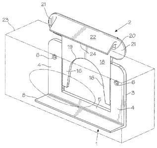
Figure 1 is an isometric view of a container holder in accordance with the
present
invention;
Figure 2 is a top view of the container holder of Fig. 1;
Figure 3 is an exploded, isometric view of the container holder of Figs. 1 and
2;
Figure 4 is a side view of the container holder of Figs. 1-3;
Figure 5 is a rear view of the container holder of Figs. 1-4;
Figure 6 is a cross-section taken generally along line 6-6 of Fig. 5;
Figure 7 is an isometric view of a second embodiment of the container holder;
and
Figure 8 is an isometric view of a third embodiment of the container holder.
DETAILED DESCRIPTION OF THE INVENTION
With reference to Figs. 1 to 5, the basic elements of a first embodiment of
the
container holder include a lower jaw 1 and an upper jaw 2 slidable in the
lower jaw 1.
The lower jaw 1 includes a generally U-shaped back plate 3 defined by a pair
of
sides or arms 4 interconnected at their bottom ends by a crossbar 5.
Countersunk
holes 6 near the top ends of the arms 4 receive screws (not shown) for
mounting the
jaw 1 on a wall or other vertical surface_ A rectangular ledge 8 extends
outwardly and
preferably slightly upwardly from the bottom edge of the crossbar 5. The angle
between
2

CA 02678426 2016-04-13
the back plate 3 and the ledge 8 is 86-900 and preferably 886, but can be
larger or
smaller. Reinforcing ribs 9 (Fig. 5) extend between the front and rear edges
of the
bottom of the ledge 8 to strengthen and limit flexing of the ledge.
A rack defined by a plurality of teeth 11 is provided on the inside edge of
each
side 4 for engaging teeth 12 on the bottom outside edges of the upper jaw 2.
Each
tooth 11 is triangular when viewed from the front or the rear. As best shown
in Fig_ 6,
the outer free edge of each tooth 11 contains a generally V-shaped notch with
the outer
arm 13 of the V being longer than the inner arm 14 thereof. The outer free
edge of each
of the teeth 12 on the upper jaw 2 has an outwardly extending complementary V-
shaped configuration when viewed from above, i.e. includes a V-shaped
projection.
Moreover, at least the rear surfaces of the teeth 12 are spaced slightly
inwardly from the
rear surfaces of the sides 4 and the resilient arms 16 carrying the teeth 12
on the upper
jaw 2 are thinner than the sides 4. The purpose of this arrangement is to
avoid
frictional contact between the upper jaw 2 and a vertical surface carrying the
holder,
making sliding of the upper jaw 2 relative to the lower jaw substantially
easier than if
there was full contact between the jaw 2 and the vertical surface.
The upper jaw 2 includes a generally T-shaped back plate 18 with an inverted U-

shaped recess 19 in the stem of the T between the arms 16. The back plate 18
is
thinner than the back plate 5 of the lower jaw 1. The arms 16 are slightly
resilient so
that they can flex slightly when the teeth 12 engage the teeth 9 which permit
vertical
movement of the upper jaw 2 relative to the lower jaw 1 even when the teeth 9
and 12
are meshing. A rectangular opening 20 in the top of the back plate 18
facilitates manual
manipulation of the upper jaw 2 when assembling the holder. When the upper jaw
2 is
3

CA 02678426 2009-09-11
slid fully into the lower jaw 1, wings 21 on the top of the back plate 18
engage the top
ends of the arms 4 of the lower jaw limiting movement of the upper jaw into
the lower
jaw. A rectangular ledge 22 extends outwardly and downwardly from the top edge
of
the upper jaw 2 for engaging the top surface of a container 23 such as a
tissue box
(Figs. 1 and 4). While the bottom, outer free edge 24 of the ledge 22 can be
straight (as
shown in Figs. 1 to 4), the ledge can have a convex outer edge 26 (Fig. 7) or
a serrated
(sawtooth) outer edge 27, for gripping the container 23 (Fig. 8). Moreover, a
concave
groove 28 (Figs. 7 and 8) can be provided in the free edge 24, 26 or 27 to
facilitate
gripping of the ledge 22 with a thumb or a finger.
As mentioned above, the container holder is mounted on a vertical surface such
as a wall using screws which are inserted through the holes 6 in the backplate
3 of the
lower jaw 1. The backplate 18 of the upper jaw 2 is then slid downwardly
between the
arms 4 of the lower jaw 1. A container 23 is placed between the ledges 8 and
22 of the
lower and upper jaws 1 and 2, respectively. The upper jaw 2 is pushed
downwardly
until the outer, free edge 24 of the ledge 22 presses against the top of the
container 23.
In the container retaining position of the upper jaw 2, the teeth 12 on the
upper jaw 2
meshes the teeth 9 on the lower jaw 1. As mentioned above, the arms 16 of the
upper
jaw 2 are slightly resilient permitting vertical movement up of the upper jaw
when the
teeth 9 and 12 are meshing. In order to remove the container 23 from the
holder, it is
merely necessary to pull the upper jaw 2 upwardly out of the lower jaw 1.
4

Representative Drawing
A single figure which represents the drawing illustrating the invention.
Administrative Status

For a clearer understanding of the status of the application/patent presented on this page, the site Disclaimer , as well as the definitions for Patent , Administrative Status , Maintenance Fee  and Payment History  should be consulted.

Administrative Status

Title Date
Forecasted Issue Date 2017-03-07
(22) Filed 2009-09-11
(41) Open to Public Inspection 2010-03-11
Examination Requested 2014-09-02
(45) Issued 2017-03-07
Deemed Expired 2019-09-11

Abandonment History

There is no abandonment history.

Payment History

Fee Type Anniversary Year Due Date Amount Paid Paid Date
Application Fee $200.00 2009-09-11
Maintenance Fee - Application - New Act 2 2011-09-12 $50.00 2011-09-08
Maintenance Fee - Application - New Act 3 2012-09-11 $50.00 2012-08-23
Maintenance Fee - Application - New Act 4 2013-09-11 $50.00 2013-09-05
Maintenance Fee - Application - New Act 5 2014-09-11 $100.00 2014-08-28
Request for Examination $400.00 2014-09-02
Maintenance Fee - Application - New Act 6 2015-09-11 $100.00 2015-09-03
Maintenance Fee - Application - New Act 7 2016-09-12 $100.00 2016-09-07
Final Fee $150.00 2017-01-23
Maintenance Fee - Patent - New Act 8 2017-09-11 $100.00 2017-09-05
Owners on Record

Note: Records showing the ownership history in alphabetical order.

Current Owners on Record
BLANCHARD, NORMAND
Past Owners on Record
None
Past Owners that do not appear in the "Owners on Record" listing will appear in other documentation within the application.
Documents

To view selected files, please enter reCAPTCHA code :


To view images, click a link in the Document Description column. To download the documents, select one or more checkboxes in the first column and then click the "Download Selected in PDF format (Zip Archive)" or the "Download Selected as Single PDF" button.

List of published and non-published patent-specific documents on the CPD .

If you have any difficulty accessing content, you can call the Client Service Centre at 1-866-997-1936 or send them an e-mail at CIPO Client Service Centre.


Document
Description 
Date
(yyyy-mm-dd) 
Number of pages   Size of Image (KB) 
Cover Page 2010-02-22 1 38
Abstract 2009-09-11 1 10
Description 2009-09-11 4 151
Claims 2009-09-11 4 107
Drawings 2009-09-11 4 82
Representative Drawing 2010-02-11 1 13
Representative Drawing 2017-02-01 1 13
Cover Page 2017-02-01 1 39
Description 2016-04-13 4 147
Claims 2016-04-13 3 92
Drawings 2016-04-13 4 84
Assignment 2009-09-11 2 61
Returned mail 2018-11-07 2 103
Fees 2013-09-05 1 33
Prosecution-Amendment 2014-09-02 1 22
Examiner Requisition 2016-02-24 3 213
Amendment 2016-04-13 8 230
Final Fee 2017-01-23 1 26