Note: Descriptions are shown in the official language in which they were submitted.
CA 02678558 2009-08-17
WO 2008/103907 PCT/US2008/054723
AUTOMATED PIZZA PREPARATION AND VENDING SYSTEM
This application claims priority to provisional application no. 60/891,218,
filed February 22,
2007, which is incorporated by reference herein.
Field of the Invention
The present invention generally relates to the field of food preparation and
vending
systems. More specifically, the present invention relates to an automated
system for
preparing and vending individual pizzas for consumption.
Back2round of the Invention
Pizza is a very popular food in many countries throughout the world. Although
pizza
is a relatively simple food, having generally just three ingredients in its
most basic form--
dough, tomato sauce and cheese, there are many variations in the taste and
quality of the
finished, cooked pizza. There are also a number of ways of preparing and
cooking pizza. The
most common and typical method of preparation and cooking is what is referred
to as "fresh"
pizza. This method generally involves the flattening of the dough, placement
of the sauce and
cheese on the dough, and subsequent cooking in an oven. Once removed from the
oven, the
"fresh" pizza is consumed while it is still hot or warm.
The popularity of pizza has led to many different methods of preparation and
cooking
in order to provide pizza to consumers in many different forms, such that it
is available to be
consumed in virtually any place. The typical method of preparation and
cooking, as outlined
above, is generally performed in a pizza parlor, or in an individual's home,
where the
CA 02678558 2009-08-17
WO 2008/103907 PCT/US2008/054723
ingredients, as well as an oven are available. The pizza is then consumed at
the pizza parlor,
or at the home, whichever is more convenient. However, this typical method of
preparation
and cooking requires one to have the necessary ingredients available, and to
also have an oven
available for use. These requirements restrict the availability of "fresh"
pizza.
Several approaches have been developed to address these requirements of pizza
preparation, i.e., the requirement for the necessary ingredients, and the
requirement for the
oven. One such approach involves the use of frozen pizzas. This approach
eliminates the
requirement for having the necessary ingredients on hand. Instead, the
prepared, frozen pizza,
which can be purchased at a store ahead of time and stored in one's freezer,
can then be
cooked in one's oven at any convenient and desirable time. However, the use of
frozen pizzas
still requires one to have access to an oven. Also, the resulting pizza is
sometimes not of the
same taste quality as "fresh" pizza, i.e., where the ingredients are assembled
together and then
cooked right away.
Another approach which has been developed in order to make pizza more readily
available in more places, is the use of vending systems or vending machines.
These machines
typically use prestored, frozen pizza which are then cooked in an oven within
the vending
machine and then dispensed to a customer. This approach eliminates the need
for having the
necessary ingredients and for having an oven available. However, such vending
machines
typically use frozen pizza as the starting point. As a consequence, the
resulting pizza
produced by such a machine is not really considered "fresh" pizza, nor does
its resemble that
of "fresh" pizza.
Yet another approach to preparing pizza by way of vending machines is the use
of
fresh ingredients in order to better provide what is considered a "fresh"
pizza. Such machines
are disclosed in, for example, U.S. Patent Nos. 5,921,170 and 6,086,934 both
to
Khatchadourian et al., the contents of which are hereby incorporated herein by
reference.
Summary of the Invention
The present invention is directed to an apparatus for preparing and cooking
pizza
using fresh ingredients, the apparatus being in the form of a vending type of
machine. By
way of a keypad, touchpad, display or other user interface provided on the
machine, a user
2
CA 02678558 2009-08-17
WO 2008/103907 PCT/US2008/054723
specifies the type of pizza that they want. The machine then proceeds to
combine the
ingredients needed to create the requested pizza, cooks the pizza, as
appropriate, places it in a
box, and dispenses the boxed pizza to the user or customer.
Generally, the pizza preparation machine (also referred to as the pizza making
apparatus or machine) is provided with fresh ingredients in various types of
appropriate
containers. For example, the dough may be provided in the form of sealed
canisters or tubes,
which are opened in an automated fashion. Slices of dough may be cut from the
dough
canisters for each pizza which is to be made. Sauce may be provided in the
form of sealed
tubes, bags, or containers, whereby a controlled amount of the sauce may be
dispensed by
way of a controlled dispensing system, such as a pump or similar mechanism.
Finally, the
cheese may be provided in a bag or other container, whereby a measured amount
of cheese
may be dispensed and provided on each pizza as it is prepared.
The pizza preparation machine may also include a refrigerated section for
maintaining
ingredients which need to be refrigerated at an appropriate temperature in
order to maintain
the freshness of such ingredients, as well as to maintain a proper sanitary
and food handling
environment.
The pizza preparation machine may also include an oven section where the pizza
is
cooked. Additionally, the pizza preparation machine may also include a box
formation
section where a box may be formed for the pizza to be placed inside the box.
For example,
the pizza preparation machine may be provided with a stack of box blanks,
i.e., folded boxes,
such that the box formation section retrieves an individual box blank and
folds it as
appropriate in order to create a three-dimensional box. The pizza which has
been cooked by
the oven can then be inserted inside the formed box. The formed box may then
be closed, and
then dispenses to the user or customer by way of an opening in the pizza
preparation machine.
The pizza making apparatus may also include appropriate controlled movement
mechanisms employing controlled motors or other drivers for moving various
elements within
the machine in order to create the pizza and then transfer the pizza through
the various
sections within the machine. For example, such mechanisms may include a
controlled knife
for cutting a specific piece of dough, horizontal and vertical transfer
mechanisms for moving
the cut dough to the various sections of the machine, as well as controlled
movement
3
CA 02678558 2009-08-17
WO 2008/103907 PCT/US2008/054723
mechanisms for dispensing the ingredients or toppings in a specified amount
and in a
specified location. Additionally, sensors may be positioned in specified
locations within the
machine to indicate the presence or absence of particular events in order to
facilitate the pizza
making process. For example, sensors may be used to indicate the movement of
the dough to
a sufficient position to thereby indicate a predetermined thickness of dough
which is to be cut
by the knife. Such sensors and controlled movement mechanisms may be operated
in
conjunction with a programmed processor or other electronic controller device.
Description of the Drawin2s
The above and still further objects, features and advantages of the present
invention
will become apparent upon consideration of the following detailed description
of a specific
embodiment thereof, especially when taken in conjunction with the accompanying
drawings
wherein like reference numerals in the various figures are utilized to
designate like
components, and wherein:
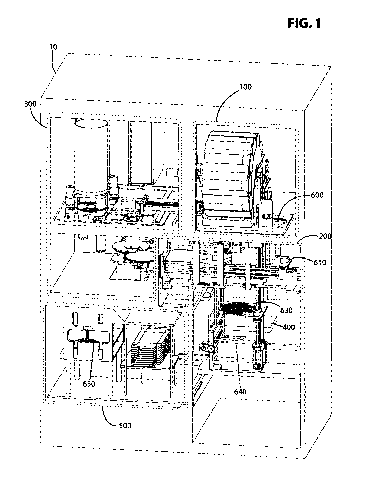
FIG. 1 is a front perspective view of the pizza making apparatus according to
one
embodiment of the present invention;
FIG. 2 is a front view of the pizza making apparatus of FIG. 1;
FIG. 3 is a perspective view of the canister handling and dough portioning
system of
the pizza making apparatus;
FIG. 4 is a left perspective view of the canister handling and dough
portioning system
of the pizza making apparatus;
FIG. 5A is a front cross sectional view of the canister lid removal system,
with the
canister about to enter the lid removal clamp;
FIG. 5B is a front cross sectional view of the canister lid removal system,
with the
canister pushed through lid removal clamp;
FIG. 5C is a front cross sectional view of the canister lid removal system
canister
retracted back out of the clamp, with the lid removed;
4
CA 02678558 2009-08-17
WO 2008/103907 PCT/US2008/054723
FIG. 6A is a right perspective view of the canister lid removal system with
the lid
about to be removed;
FIG. 6B is a right perspective view of the canister lid removal system with
the
removed lid being kicked into the lid container;
FIG. 7 is a cross sectional view of the lid removal and dough portioning
system, with
the canister into the dough knife hub and a portion of dough being cut;
FIG. 8A is a front right perspective view of the canister handling and dough
portioning
system, as well as the dough pressing and par-baking system, with a newly cut
piece of
dough;
FIG. 8B is a front right perspective view of the canister handling and dough
portioning
system with the newly cut piece of dough being lowered out of the refrigerated
area;
FIG. 8C is a perspective view of the dough pressing system with the newly cut
piece
of dough about to be transferred to the hot press platform;
FIG. 8D is a perspective view of the dough pressing system with the dough
portion
just having been transferred to the hot press platform;
FIG. 8E is a perspective view of the dough pressing system with the press
platform
under the top press plate;
FIG. 8F is a perspective view of the dough pressing system with the pushing
arm in
the retracted position;
FIGs. 9A to 91 are front cross sectional views of the hot press and par-baking
system
depicting various stages of the pressing process;
FIG. 10A is a front right perspective view of the dough pressing system and
the pie
topping area, showing the newly made pie crust being transferred to the
topping area;
FIG. 10B is a front right perspective view of the pie topping area, showing
the sauce
spreading process;
FIG. 11A is a front left perspective view of the pie topping area showing the
cheese
dispensing mechanism;
CA 02678558 2009-08-17
WO 2008/103907 PCT/US2008/054723
FIG. 11B is a front right perspective view of the cheese dispensing mechanism
with
the cheese canister and the canister base removed to depict the bag insertion
process;
FIG. 11C is a front exploded view of the cheese dispensing mechanism;
FIGs. 11D and E are front left perspective views of the pie topping area
showing the
cheese dispensing and spreading process;
FIGs. 12A to 12C are front right perspective views of the pie oven transfer
system;
FIG. 13A is a rear sectional view of the conveyor oven;
FIG. 13B is a rear perspective view of the oven and the packaging system
showing the
pizza about to be transferred to a box;
FIG. 14A is a front view of the box forming system;
FIGs. 14B to 14D are front right perspective views of the box forming system,
depicting the box separation and opening sequence;
FIGs. 15A to G are left side views of the rear flap folding mechanism,
depicting
various stages of the box flap closing process;
FIG. 16 is a block diagram of a first embodiment of an electronic control
system for
the present invention;
FIG. 17 is a block diagram of an alternative embodiment of an electronic
control
system for the present invention; and
FIG. 18 is a flowchart of the process performed by the present invention to
prepare a
pizza.
Detailed Description of the Invention
Referring now to FIG. 1, an apparatus 10 for making pizza is illustrated. The
apparatus includes a dough-storage and handling area 100, a dough pressing and
par-baking
area 200, a topping storage and dispensing area 300, an oven 450, and a
packaging area 500.
The apparatus also includes mechanisms that serve to transfer the pizza
between these areas.
These transfer mechanisms include the dough slice elevator 600, the plate
transfer arm 610,
6
CA 02678558 2009-08-17
WO 2008/103907 PCT/US2008/054723
the elevator transfer arm 620, the pizza elevator 630, the oven transfer arm
640, and the box
transfer arm 650 (not visible in FIG. 1).
Referring now to FIG. 2, the dough storage and handling system 101 is enclosed
in a
refrigerated compartment 102, which is kept at a temperature which is
preferably between 18
and 24 F, and the topping storage and dispensing area 300 is enclosed in a
refrigerated
compartment 301, which is kept at a temperature which is preferably between 34
and 40 F.
Referring now to FIGs. 3-4, the dough storage area includes a canister Ferris
wheel
104 that houses a plurality of canisters 106. Each canister 106 is filled with
dough and is
sealed at its rear with a moving piston 108 and at its front with a lid 109.
Each canister
preferably has an internal diameter of four inches and is approximately ten
inches in axial
length. Alternatively, the internal diameter may be as much as five inches or
more and the
axial length may vary from eight to twelve inches. Of course, other
configurations may be
used depending on the particular application.
The canisters 106 are stored within Ferris wheel-like mechanism 104, which
rotates to
present each canister to the dough cutting station 110. The canister received
in the dough
cutting station will be referred to as canister 107. The dough cutting station
assembly 110
includes an extruder mechanism 120, a lid removal clamp 130, a lid kicker
mechanism 140
and a dough-cutting mechanism 150. When the canister Ferris wheel mechanism
104
introduces the canister 107 to the cutting station, the canister is centered
axially with extruder
120, lid remover 130 and dough cutter 150 mechanisms.
Referring now to FIGs. 5A-5C, the canister lid removal process will now be
described. First, the extruder mechanism pushing shaft 121 advances, bringing
the extruder
pusher plate 124 into contact with the internal piston 108 of the canister 107
to eventually
push the front face of the latter beyond the lid removal clamp 130. The
canister lid removal
clamp includes two spring loaded semicircular blocks, 131 and 132, arranged
vertically one
on top of the other, such that when the canister is pushed against them from
the left, they are
deflected up and down, respectively, to allow the canister to pass through. In
an alternative
embodiment, one of the blocks may be fixed, with the other block being spring
loaded so that
it can deflect up and down with respect to the fixed block. Referring to FIG.
5B, when the lid
109 clears these blocks, they retract back onto the canister body. Upon the
initial contact of
7
CA 02678558 2009-08-17
WO 2008/103907 PCT/US2008/054723
the extruder pusher plate 124 with the internal piston 108 of the canister, a
set of three spring
loaded hooks 122 arranged along the perimeter of the extruder pusher plate 124
are deployed
and act to engage the back end of the canister to permit the extruder to pull
the canister back
out of the lid removal clamp.
As the canister retracts back out of the lid removal clamp 130, the lid 109 is
pushed
off the canister as it is prevented from retracting by the lid removal clamp.
Referring now to
FIG. 6A, the lid 109 is moved out from in front of the canister by a kicker
mechanism 140
that knocks the lid into a receptacle 144 in the rear of the canister area. In
an alternative
embodiment, the lid receptacle may have an upward slope at its entrance, such
that once the
lids are pushed in they can no longer come back out. Optionally, a photosensor
may be used
to detect whether or not the lid has properly been moved out.
Referring now to FIG. 7, after the canister is opened, the extruder now pushes
the
canister into the dough cutting hub 154 and against a lip 156 at the edge of
the dough cutting
hub. The canister is now ready to extrude dough slices when an order is
placed. Upon the
reception of an order for a pizza, the dough cutting blade 152 is raised. This
opens the way
for the extruder to push dough out of the canister and through the cutting hub
154. In this
case, the canister itself is prevented from advancing by the lip 156, such
that the pressure
generated on the piston 108 eventually disconnects the dough from the canister
wall and
pushes it through the dough cutting hub 154. As the dough advances, it is
eventually detected
by an electronic photosensor 158, which stops the extruder from pushing once
the dough has
been pushed a predetermined amount, i.e., when a predetermined thickness of
dough has been
pushed out of the dough canister. The position of the photosensor essentially
determines the
thickness of the dough slice. The dough cutting blade 152 now descends and
cuts the dough
to thereby create a dough slice. The newly cut slice falls onto an elevator
surface 602, which
lowers the slice out through the refrigerated area down to the level of the
press mechanism.
Referring now to FIGs. 8A-F, the dough puck or dough slice transfer to the
press
mechanism will be discussed. The press area includes a circular heated press
top plate 202
that moves vertically from an uppermost position to a lowermost position, a
circular heated
lower press plate 204 that moves along the horizontal axis from a leftmost
position to a
rightmost position, and a pushing arm 610 that moves along the horizontal
axis. The newly
8
CA 02678558 2009-08-17
WO 2008/103907 PCT/US2008/054723
cut slice or piece of dough will be referred to as the dough puck 160. Upon
reception of an
order for a pizza, the press top plate 202 will move to its uppermost
position, the press lower
plate 204 will move to its rightmost position, where it will be adjacent to
the dough slice
elevator surface 602 when the latter is lowered with the freshly cut piece of
dough. In an
alternative embodiment, the lower press plate 204 may be fixed, and the top
press 202 plate
may then move with respect to the lower press plate 204. The plate transfer
arm 610 now
moves the slice of dough onto the lower press plate 204. Referring now to FIG.
8D, as the
slice approaches the center of the bottom press plate, the arm 610 is
deflected up when it
contacts the plate transfer arm deflector 612. The sudden upward movement
caused by this
deflection severs the contact between the pusher arm 610 and the slice of
dough. This insures
that the dough slice remains centered as the lower press plate moves back to
position itself
under the top press plate 202. The dough puck 160 is now in position to be
pressed.
In order to achieve fast and consistent results in producing pie crusts that
are rigid
enough to be pushed around to the various stations in the machine while
maintaining a certain
amount of lightness and airiness expected of pie crusts, the pressure buildup
between the two
plates must be controlled in order to prevent blowouts, deformities of the pie
crusts, or crusts
with bad texture. Excessive pressure can be caused by many factors such as
variances of
dough portion sizes, dough temperature, press temperature, differences of
temperature
between top and bottom plates, and even variances in the positioning of the
dough. There
must however be a certain amount of tolerance to allow for normal fluctuations
for each of
these factors. The goal is to press out the dough into pie crusts of
consistent thickness. This
is achieved through the press design and a particular pressing sequence, as
described herein.
Referring now to FIG. 9A, the press mechanism includes heated top and bottom
plates, 202 and 204, respectively. The top plate is actuated vertically due to
the rotation of a
lead screw mechanism that has two halves, 210 and 211, each having opposite
directional
threads. The rotation of the lead screw makes corresponding brackets 212 and
213 to move in
opposite directions. These brackets, in turn, are each connected to a pair of
levers that are in
turn connected to a push plate 216. The top press plate 202 hangs on this push
plate through
shoulder screws 218, with light springs 219 around the shoulder screws between
the two
plates, to help assure that the press plate 202 does not get wedged at a non-
horizontal angle,
due to the screws.
9
CA 02678558 2009-08-17
WO 2008/103907 PCT/US2008/054723
The top press plate therefore descends to squeeze out and shape the dough
slice 160
into, for example, an 8" pie crust. When the top plate 202 reaches its
lowermost position, it
forms a cavity, which is then filled up by the dough slice 160. The dough
slice therefore takes
the shape of this cavity. The top and bottom press mechanisms are heated to
par-bake the slice
of dough to the point where the dough is rigid enough to be pushed around from
station to
station.
Referring now to FIGs. 9A-I, therein is illustrated the operation of the press
mechanism. The following table lists the steps of the pressing sequence shown
in each figure,
from FIG. 9A to FIG. 91.
CA 02678558 2009-08-17
WO 2008/103907 PCT/US2008/054723
FIG Pusher Plate Description
Movement
9A Down Press plate hanging from pushing plate.
9B Down Press top plate sitting on top of pie, with a gap between press plate
& pushing plate.
9C Down Pie being squeezed, no gap between plates.
9D End of travel Both plates in lowermost position. Short pause in this
position.
9E Up Press plate being pushed up against pushing plate due to pressure
buildup.
9F Midpoint A Pushing plate moves up and stops at Midpoint A. Somewhere
between lowermost
point & Midpoint A, press plate drops back on top of pie due to release of
pressure.
9G Down Pushing plate goes back down. Press plate sitting on top of pie.
9H Midpoint B Pusher plate stationary at Midpoint B, while press plate is
raised up by rising dough.
Midpoint B is the uppermost allowable rise position for the press plate.
91 Up
Referring now to FIGs. 9A-B, as the pushing plate is lowered, the top press
plate first
comes into contact with the slice of dough 160 and briefly stays there as the
pushing plate
continues its downward movement. Referring now to FIG. 9C, eventually the
pushing plate
comes back into contact with the top press plate and begins applying pressure
on the dough
slice through the top press plate. The slice is squeezed with consecutive slow
bursts of
downward movement, to allow the dough sufficient time to soften under the heat
and expand
without tearing or creating air pockets.
Referring now to FIG. 9D, as the top press plate reaches its lowermost
position, the
dough fills out the cavity between the plates and takes on the flat circular
shape with slightly
raised edges. In this position, with the dough slice in full contact with the
press, the par-
baking process begins, but as the cavity is fully sealed, there is a great
increase in pressure
between the plates.
Referring now to FIG. 9E, in order to limit the rise in pressure, after a
short delay, the
pushing plate begins to move back up in timed small spurts. Initially due to
the pressure, the
top press plate is pushed up against the pusher plate. Referring now to FIG.
9F, as the plates
continue to rise the seal between the plates is eventually broken and some of
the pressure is
evacuated, causing the top press plate to fall back onto the pie, continuing
the par-baking
process. The exact point when the top press plate falls back onto the pie can
be at any of a
range of different positions. The pushing plate needs only to retract up to a
pre-determined
11
CA 02678558 2009-08-17
WO 2008/103907 PCT/US2008/054723
upper limit (midpoint A) where the seal between the plates is certain to have
been broken and
the pressure relieved. Accordingly, the shoulder screws 218 must be of
sufficient length to
allow the press plate to fall back onto the pie when the pressure drops.
Referring now to FIGs. 9G-H, with the press plate on the pie, the par baking
process
continues and similar to any dough baking process causes the pie to rise. The
press plate
therefore rises with the pie. However, the pusher plate comes back down to a
second position
(midpoint B) and remains at that point for the duration of the par-baking
process, for example,
approximately 20-30 seconds. This position sets an upper limit to the rise of
the press plate
and the dough under it, allowing the system to produce pies of approximately
equal thickness.
As the dough continues to dry out in this position, its maximal thickness gets
set.
In an alternate embodiment, the pressing and par baking may be performed at
two
different stations rather than in one location with a single mechanism. The
pie may first be
pressed out under the press mechanism and may subsequently be par baked in a
heated
chamber located between the press mechanism and the pie topping plate. This
method would
have the advantage of reducing the lag time between pies, because a new pie
can begin to be
cut and pressed out as soon as the initial pressing of the previous pie is
completed, instead of
waiting for the additional par-baking time.
Referring now to FIGs. 1OA-B, as the pressing and par-baking cycle approaches
completion, the topping area entry door 400 opens, the turntable mechanism 302
rotates to
position the topping plate 304 in line with the press bottom plate 204.
Simultaneously, the
pres top plate 202 rises, and the plate transfer arm 610 then pushes the par-
baked pizza crust
onto the pie topping plate 304. The plate transfer arm 610 then retracts to
its original position.
The dough pressing area 200 is now ready to prepare the next pizza.
Referring now to FIG. 10B, the turntable 302 rotates to position the perimeter
of the
pizza crust 260 under the sauce tube end 309. The crust is then rotated by the
pizza topping
plate 304. Simultaneously to this, the sauce pump 310 draws sauce from the
sauce bag 306
contained in the sauce container or box 307 through the sauce tube 308, and
dispenses it onto
the dough crust 260. The spinning of the plate causes the sauce to spread
around the
perimeter of the pie crust. When the perimeter of the pizza crust is covered
with sauce the
sauce pump stops pumping momentarily. During this pause, the turntable 302
rotates to now
12
CA 02678558 2009-08-17
WO 2008/103907 PCT/US2008/054723
position the sauce tube end 309 further towards the center of the pizza crust.
The sauce pump
310 then restarts the flow of sauce to cover the inner portion of the pie with
sauce. This
process is repeated once more by positioning the sauce tube end near the
center of the pie
crust and dispensing a small amount of sauce in the middle of the pie crust.
Of course, a
greater or lesser number of sauce dispensing cycles may be used, depending on
the particular
application. Optionally, a photosensor may be used to detect the presence of a
pizza crust,
and disable the sauce dispensing mechanism if a pizza crust is not detected,
so as to prevent
the dispensing of sauce in the event of a malfunction or improper operation.
Referring now to FIG. 11A, therein is illustrated two cheese dispensing
mechanisms,
320 and 350 respectively. Once the pizza is covered with sauce, the turntable
302 rotates to
position the pizza crust 260 under the first cheese chute 348 or the second
cheese chute 352,
depending upon which cheese mechanism 320 or 350 is in use. The present
description refers
to the operation of the first cheese mechanism 320. The second cheese
mechanism is
substantially similar to the first mechanism.
Referring now to FIG. 11B, the cheese dispensing mechanism includes a
cylindrical
silo 322, for example, 8 inches in diameter, that contains a bag 324 of
granulated cheese. The
granulated cheese is commercially available and includes cubes of 1/8th of an
inch that may be
provided in sealed bags. The cylinder diameter may be increased to increase
the amount of
cheese within each canister, but in such a case the bag must also be enlarged.
The silo has a
removable base 326. The base includes a circular disk made out of food grade
plastic. The
base has a dispensing hole 328, for example, approximately one inch in
diameter, that permits
the cheese to flow out. The base also has an agitating arm 332 that is shaped
such that it can
close the cheese dispensing hole 328 when made to stop at a particular
position. The agitating
arm is also shaped to have an extending scraper 333 that serves to wipe the
bottom edge of the
canister and promote a proper flow of cheese towards the dispensing hole.
The cheese bag 324 is inserted into the silo by removing the silo from the
mechanism,
turning it upside down and removing the base 326. At this point the cheese bag
324 may be
inserted into the silo, with one end sticking out. The top of the bag is then
cut or ripped open
and folded over the edge of the silo, similar to a trash bag over a trash can.
The base 326 may
then be fitted into the silo, thereby wedging the bag in place. The base 326
may then be
13
CA 02678558 2009-08-17
WO 2008/103907 PCT/US2008/054723
locked in position on the silo with a pair of latches 330. The silo may then
be flipped back to
a right side up position without fear of spillage due to the agitating arm 332
closing the exit
hole 328 in the base 326. The cheese silo, with the newly installed cheese bag
in it is now
installed onto a support platform 338 on top of the cheese dispensing system.
A coupling
shaft 335 of the agitating arm, extending out from the bottom of the cheese
silo base, is
inserted through a hole on the silo support platform 338 and into a mating
hole in the center
drive shaft 345. The cheese silo is then locked into position with a pair of
latches 340 that are
positioned to insure that the cheese exit hole 328 of the silo base lines up
with a
corresponding hole 339 on the support platform. Just below these exit holes is
measuring
cylinder 342 that is inserted into the canister support platform hole 339 and
is removable
without tools in order to be cleaned. The measuring cylinder 342 is closed at
the bottom by a
circular rotating trap door 343. The latter has cutout holes that, when
rotated to the correct
position, allow the cheese to flow out. The rotating door is connected to the
drive shaft 345,
but it can be easily removed without tools in order to be cleaned by first
removing the cheese
silo and the measuring cylinder 342.
Referring now to FIG. 11C, a single DC motor 344, whose direction may be
reversed
and the speed controlled, is used to drive both the agitating arm and the
measuring cylinder
trap door. The motor is coupled to the drive shaft 345. In this case it is
through a set of
sprockets and a chain, but it may also be mounted directly to the drive shaft
by being placed
under the entire mechanism. The drive shaft 345 has a pair of internal spring-
loaded drive
pins, one pin 346 near the bottom which couples to the measuring cylinder trap
door 343 and
the other pin 347 further above which couples to the bottom of the agitating
arm coupling
shaft 335. When the drive shaft 345 rotates one way the agitating arm coupling
shaft 335 is
engaged to actuate the cheese actuating arm, and when the drive shaft 345
rotates in the
opposite direction, the buffer door 343 is engaged.
Referring now to FIG. 11D, therein is illustrated the cheese dispensing
process. The
first step in the cheese dispensing process is to fill the measuring cylinder
342 with cheese.
This is accomplished by rotating the agitating arm 332 located inside the
silo, and allowing
the cheese to flow through the dispensing hole 328 at the base of the silo.
Alternatively, the
arm may simply be rotated several times without actually measuring or
detecting that the
measuring cylinder is full, with the assumption that a sufficient number or
turns will
14
CA 02678558 2009-08-17
WO 2008/103907 PCT/US2008/054723
adequately fill up the cylinder. In this alternative embodiment, a count or
record must be kept
to know approximately how much cheese remains in the silo. Otherwise, in the
first
embodiment, a sensor is mounted on the top of the cheese measuring cylinder to
detect the
presence of cheese at the top of the cylinder. In this case, when the sensor
detects the
presence of cheese near the top of the measuring cylinder, the agitating arm
simply rotates
enough to close the dispensing hole in the base of the silo. This method has
the advantage of
being able to detect if the measuring cylinder never gets filled up despite a
sufficient number
of turns of the agitating arm, which would indicate an empty silo condition.
The measuring
cylinder trap door 343 should be positioned such that it closes the bottom of
the cylinder in
order for the cylinder to fill up. A second sensor may also be used near the
bottom of the
measuring cylinder to detect that the cylinder has properly emptied, i.e.,
dispensed the cheese
inside the cylinder.
The filling of the measuring cylinder preferably occurs prior to the pie crust
being
moved under either of the cheese dispensing mechanisms. After getting topped
with sauce,
the pie crust 260 is rotated to place the cheese chute 348 near the center of
the pie.
Referring now to FIG. 11E, the measuring cylinder trap door 343 is rotated to
a
position that allows the cheese within the measuring cylinder to fall onto the
pie. The
measuring cylinder 342 may optionally be vibrated to facilitate the emptying
of the cylinder.
This may be accomplished either with a separate vibrating device mounted on
the measuring
cylinder (e.g., a hammer type mechanism), or by adding dimples on the trap
door 343 such
that, as the door is rotated, it collides with a bracket that touches the
measuring cylinder, thus
imparting some vibration to the measuring cylinder.
As the cheese falls onto the pie, some of it spreads out beyond the perimeter
of the
cheese chute 348, covering a large section of the center of the pie, but most
of it remains
backed up within the cheese chute 348. The turntable 302 then rotates to
position the cheese
chute closer to the perimeter of the pie crust 260. Simultaneously, the
topping plate 304
begins to rotate. As the cheese chute 348 passes over sections of the pie
without cheese on it,
the cheese backed up in the chute empties out onto the pie, at a rate
determined by the gap
between the bottom of the chute and the surface of the pie, as well as the
rotation speed and
CA 02678558 2009-08-17
WO 2008/103907 PCT/US2008/054723
the shape of the rake pattern at the bottom end of the chute. The initial
rotation of the topping
plate is in a direction to push the cheese against the rake extensions at the
bottom of the chute.
The cutout pattern at the bottom of the chute has three sections: a section
with rake-
like extensions that act to spread the cheese as it flows out, a solid section
with no cutouts that
is positioned near the perimeter of the pie and serves to limit the amount of
cheese granules
falling off of the pie, and an open section that comes into play at the very
end of the cheese
spreading cycle to allow any extra cheese remaining in the chute to fall out
onto the pie.
After a timed cycle, the pie should be fully covered with cheese. However, due
to
potential variations in dough thickness, cheese quantity or the presence of
clumps in the
cheese, it is possible that not all of the cheese would have emptied from
under the cheese
chute. However, by having a relatively large opening in the cutout pattern at
the bottom of
the cheese chute, this permits the emptying of this extra cheese onto the pie
by reversing the
rotation of the topping plate for a short time after the pie has been
completely covered.
Referring now to FIGs. 12A-C, the pie transfer process to the oven will now be
described. In these drawings, the press mechanism assembly has been removed to
make the
oven transfer mechanisms more visible. Once the pizza crust is covered with
cheese, the
turntable mechanism 302 rotates to position the pie topping plate 304 in-line
with the elevator
mechanism 630. Simultaneously, the topping area exit door 420 is opened. At
this point the
elevator transfer arm 620 pushes the fully topped pie crust onto the elevator
630, then retracts
back to its original position. The turntable mechanism 302 is now free to
rotate back to the
original position to accept the next pie crust. The elevator then lowers the
pizza crust to the
level of the conveyor oven 450, and the oven transfer arm 640 pushes the pizza
crust onto the
oven conveyor belt 452. The oven transfer arm 640 then retracts back to its
original position,
as does the elevator 630.
Referring now to FIG. 13A, the oven conveyor belt 452 turns on to transfer the
pizza
crust into the oven. The pizza is cooked within the oven using a pair of
ceramic heating
elements 454 and 456 located above and below the conveyor belt, respectively.
The cooking
time is approximately one minute. The cooking time may of course, be more or
less,
depending on many factors, such as crust thickness, oven temperature, etc. To
minimize heat
loss, instead of using doors, the oven generates air curtains at its entrance
and exit openings to
16
CA 02678558 2009-08-17
WO 2008/103907 PCT/US2008/054723
keep the hot air from escaping. These air curtains are generated with the use
of two high
temperature blowers 458 & 460 located at opposite corners of the oven. These
blowers act to
circulate a current of air around the perimeter of the oven, as indicated by
the counter-
clockwise arrows. Once the cooking is completed, the oven conveyor belt re-
activates to
transfer the pizza out of the oven.
Referring now to FIG. 13B, as the pizza exits the oven it passes from the oven
conveyor belt 452 to a smaller exit conveyor belt 453. The pizza eventually
collides with a
deflector plate 462 that in turn triggers a limit switch 464 that signals for
the conveyor belt to
stop turning. Before describing the pie boxing process, the box preparation
and forming
process is now described.
Referring now to FIG. 14A, therein is illustrated the pizza box forming system
500.
The forming system includes two main areas: the box stack area 502 and the box
flap closing
area 503. The box stack area includes a stack elevator mechanism 560 that
supports the stack
of boxes 510 and the box separator belt 580 that transfers the topmost box 511
from the stack
to the box flap closing area 503. The latter includes box bender mechanism
590, a pair of flap
closing mechanisms, one in the front 530 and one in the rear 531. Finally,
there is also a box
transfer mechanism 650 that serves to push the pizza into an opened box, and
then to push the
closed box out of the machine.
Referring now to FIG. 14B, to separate a new box, the box separator belt 580
begins to
spin as the box stack elevator mechanism 560 begins to rise. The topmost box
511 eventually
comes into contact with the spinning separator belt 580. As enough pressure
develops
between the box stack and the belt, sufficient friction force is eventually
generated for the belt
to move the topmost box forward onto the box separation platform 582. A sensor
or limit
switch 584, shown with hidden lines and located above the separator platform
detects the
presence of the newly separated box and signals both the separator belt 580
and the box stack
elevator 560 mechanism to stop moving. The stack elevator then reverses
direction and
begins to descend a short distance to relieve the pressure between the box
stack and the
separator belt. This ensures that a second box is not separated, because the
previous box fully
occupies the space available between the separator platform 582 and the belt
580, whereas
there is no longer any friction between the belt and the next box on the
stack.
17
CA 02678558 2009-08-17
WO 2008/103907 PCT/US2008/054723
Referring now to FIGs. 14C-D, the box separator belt 580 now recommences
spinning
and pushes the separated box down into flap closing area 503. Referring now to
FIG. 14D,
the newly separated box is bent open by the rotation of the box bending
mechanism 590. The
box is kept in position by the box bender pushing the box against the box
support bracket 592,
shown in FIG. 14D. The box is now in position, open and ready to accept the
next pie.
Now referring to FIG. 15A, therein is illustrated the rear flap closing
mechanism 531,
and the box transfer arm mechanism 650, as well as an opened pizza box 512,
with the front
and rear left side latching tongues 513 visible, along with the rear box
closing flap 514, and
the flap top latching tongue 515, which is the top part of the box closing
flap 514.
Now, as the pie exits the oven and is centered with the box transfer arm 650,
the latter
moves forward to push the pizza into the previously opened box 512. As the
pizza advances,
it first moves over the bridge platform 526 and contacts a rotating box flap
bridge 527 which
pushes it down over the box flap 514, allowing the pie to slide freely into
the box without
interference from the box flap 514. In order not to interfere with the box
flap closing process,
the box transfer arm 650 then retracts back over the rotating flap bridge 527,
out of the box
flap closing area 503 and comes to a rest over the bridge platform 526.
At this point the front and rear flap closing mechanisms, 530 and 532,
respectively,
activate simultaneously to fold and then to close the front and rear box flaps
514. The
operation of the rear flap folder 532 will now be described, it being
understood that the front
folder 530 operates in an essentially substantially similar fashion. The sub-
components of the
front and rear flap folding mechanisms have been numbered in a similar
fashion. The
following is a description of the flap closing process.
Referring now to FIG. 15B, the rear flap closing mechanism 532 is shown from a
left
side view. The mechanism includes a flap folding and pushing block 536 that
moves down
and then up, a flap closing guide 544 that is pushed down by the flap folding
and pushing
block and is pulled back up by a pull-up spring 546, a flap closing arm 542
and finally a
stationary deflector 550 for the box flap top latching tongue. Although, the
flap folding and
pushing block 536 and the flap closing guide 544 are mounted on the same guide
shaft 534,
the actuating motor, not shown in the figure, is connected only to the flap
folding and pushing
block 536. As the latter moves down and then up the guide shaft 534, it comes
into contact
18
CA 02678558 2009-08-17
WO 2008/103907 PCT/US2008/054723
with the flap closing guide 544 and moves it as well. The flap folding and
pushing block 536
is shaped to have three features or surfaces: the side tongue bending
deflectors 537, the flap
bending deflectors 538, and the flap closing arm deflectors 539. Due to the
left hand side
view of FIG. 15B, only one of each of these features, those on the left hand
side are
illustrated. They are repeated in a symmetrical fashion on the right hand side
as well.
Referring now to FIGs. 15C and D, the flap closing cycle commences with the
downward movement of the box flap folding and pushing block 536. As the latter
descends,
the side tongue bending deflectors 537 come into contact with the side
latching tongues 513,
and bend the latter inwards. Simultaneously, the flap bending deflectors 538
come into
contact with the crease on the box closing flap 514, and bend the latter
downward. As the
flap 514 bends downward, the flap top latching tongue 515 comes into contact
with the flap
top deflector 550, and gets bent inward.
During this downward movement of the box flap folding and pushing block 536,
as it
is bending the box flap and tongues, it also pushes the flap closing guide
mechanism 544
down to a position in front of the box opening, where the latter is held by a
spring loaded
latching hook 548 that holds onto latching extensions 545 on the flap closing
guide.
Referring now to FIGs. 15E and F, the box flap folding and pushing block 536
now
rises back to its original upper position, but the flap closing guide
mechanism 544 remains in
place due to the latching hook 548. At this point, the lower section of the
flap folding and
pushing block 536, the flap closing arm deflector 539, comes into contact with
the flap
closing arm mechanism 542, which rotates upwards to push the now bent box flap
514 up. As
the upper flap tongue 515 slides against the flap closing guide mechanisms
544, it gets
inserted into the box.
Referring now to FIG. 15G, as the flap folding and pushing block 536
approaches its
uppermost position, the flap closing arm mechanism 542 rotates to a position
beyond vertical,
pushing the upper flap tongues all the way into the box, thus completing the
box closing
process. Finally, the box flap having been closed, the latching hook 548,
which keeps the flap
closing guide 544 in place, is released by the latching hook release cam 540
that is attached to
the flap folding and pushing block 536, as the latter reaches its uppermost
position. The
19
CA 02678558 2009-08-17
WO 2008/103907 PCT/US2008/054723
triggering of the latching hook 548 allows the flap closing guide 544 to be
pulled up from in
front of the box by the springs 546.
Finally, the flap folding and pushing block 536 descends from its uppermost
position
back to its original position to clear the way for the box to be pushed out.
The box is then pushed out of both the flap closing area 503 and the machine
by the
forward movement of the box transfer arm 650, which advances all the way
forward. The box
transfer arm 650 then retracts all the way back to its original position.
Finally, the pie bridge
rotating flap 527 is pulled back up to the vertical position by a solenoid
mechanism (not
shown) to position it to be ready for the next pie. The flap closing mechanism
is now ready to
accept a newly separated box to be opened for the next pie.
The various mechanisms in the machine are driven by, for example, 24V DC
motors,
as well as mechanisms actuated by AC or DC solenoids. The machine also has a
number of
heater elements used as heat sources for the oven and hot press that cook the
pie, as well as
AC fans and hot air blowers. A central controller called the Vending Machine
Controller
(VMC) handles the customer interface tasks like validating the monetary
transaction, printing
out receipts, displaying messages, and communicating with the owner/operator's
computer
system for remote monitoring and control.
The actual control of the pizza making process and the mechanisms may be
performed
by a Programmable Logic Controller (PLC), a common type of controller in
industrial
applications. In this case, the VMC and the PLC may communicate via a serial
port or some
other type of communication connection. FIG. 16 is a block diagram showing the
various
functional elements of the control system.
In an alternative configuration for the control system, the mechanism control
tasks
may be handled by customized controllers designed to handle either one
mechanism or a
group of related mechanisms, such as the canister handling and dough
portioning system, the
pressing system, the pie topping system. Whereas, the VMC manages the
controllers for each
sub-assembly or module, each individual controller would then be responsible
to govern the
movements of the mechanisms in that particular module. The advantage of this
methodology
over the PLC solution is first of all a reduction of wiring and associated
costs, as this latter
approach would only require two to four wires going from each controller to
the VMC for
CA 02678558 2009-08-17
WO 2008/103907 PCT/US2008/054723
power and communications. The controllers would in this case be located much
closer to the
sub-assembly to be controlled, thereby reducing potential noise pickup on the
wires. Finally,
customized controllers may be more economical to produce in volume. FIG. 17 is
a block
diagram of this alternative control system.
FIG. 18 is a flowchart illustrating the steps involved in the pizza ordering
and
preparation process. The VMC monitors the customer interface to see if an
order is requested
or if money has been deposited within the machine. If the Vending Machine is
ready to make
pies and when an order has been placed and the money accepted, the vending
machine
indicates to the PLC to commence a pie making cycle. The latter includes
cutting a slice of
dough, pressing and par-baking it, topping it, cooking it, and boxing it. A
new order may be
started as soon as the press area is free.
While there have been shown, described, and pointed out fundamental novel
features
of the invention as applied to a preferred embodiment thereof, it will be
understood that
various omissions, substitutions, and changes in the form and details of the
devices illustrated,
and in their operation, may be made by those skilled in the art without
departing from the
spirit and scope of the invention. For example, it is expressly intended that
all combinations
of those elements and/or steps which perform substantially the same function,
in substantially
the same way, to achieve the same results are within the scope of the
invention. Substitutions
of elements from one described embodiment to another are also fully intended
and
contemplated. It is also to be understood that the drawings are not
necessarily drawn to scale,
but that they are merely conceptual in nature. It is the intention, therefore,
to be limited only
as indicated by the scope of the claims appended hereto.
21