Note: Descriptions are shown in the official language in which they were submitted.
CA 02678786 2009-08-18
WO 2008/118518 PCT/US2008/051767
1
PCT PATENT APPLICATION
STACKABLE TRACKING SOLAR COLLECTOR ASSEMBLY
FEDERALLY SPONSORED RESEARCH OR DEVELOPMENT
[0001] This invention was made with U.S. Government support under Subcontract
Number
ZAX-6-33628-09 awarded by the National Renewable Energy Laboratory. The U.S.
Government
has certain rights to this invention.
BACKGROUND OF THE INVENTION
[0002] This invention relates to solar energy collection, and in particular to
an arrangement
for driving rows of solar collector assemblies to track the motion of the sun
relative to the earth.
The invention is more particularly directed to improvements in structure
relating to the efficient
manufacture, transport and installation of solar collector assemblies, in
particular rows of tracking
solar collector assemblies. The invention applies to solar collectors in which
the solar collector
modules include arrays of photovoltaic cells for generating electrical power,
but the same
principles can be applied also to arrangements for solar heating, for example.
[0003] Photovoltaic arrays are used for a variety of purposes, including as a
utility interactive
power system, as a power supply for a remote or unmanned site, a cellular
phone switch-site
power supply, or a village power supply. These arrays can have a capacity from
a few kilowatts to
a hundred kilowatts or more, and are typically installed where there is a
reasonably flat area with
exposure to the sun for significant portions of the day.
[0004] In general terms, these solar collector assemblies have their solar
collector modules,
typically photovoltaic modules, supported on a frame. The frame commonly
includes a frame
member, sometimes referred to as a torque tube or torque member, which serves
as an axis. A
tracker drive system, also called a tilt assembly, may be used to rotate or
rock the solar collector
assemblies of the one or more rows of solar collector assemblies about their
tilt axes to keep the
photovoltaic modules as square to the sun as possible. Usually, the rows are
arranged with the tilt
axes of the solar collector assemblies disposed in a north-south direction,
and the tilt assemblies
gradually rotate the one or more rows of solar collector assemblies throughout
the day from an
east-facing direction in the morning to a west-facing direction in the
afternoon. The solar collector
assemblies are brought back to the east-facing orientation for the next day.
CA 02678786 2009-08-18
WO 2008/118518 PCT/US2008/051767
2
[0005] One solar collector arrangement of this type is shown in Barker et al.
U.S. Pat. No.
5,228,924. There, each row of panels is affixed to a horizontal pivot shaft
that is supported on two
or more support piers on which the pivot shaft is journaled. A drive mechanism
is mounted on one
of the piers, and pushes against the solar panel at some point that is
displaced from the shaft. In
that case, the drive is of the screw type, and as a drive motor rotates, a
shaft retracts or extends to
rotate the row of panels in one direction or the other. In this arrangement,
each row of panels has
its own respective drive mechanism, and so these all have to be synchronized
to follow the sun
together. Other designs, such as that shown in US patent number 6,058,930,
employ a single
actuator to control multiple rows of solar panels.
BRIEF SUMMARY OF THE INVENTION
[0006] An example of a solar collector assembly comprises a frame having a
frame member
defining a tilt axis. A solar collector is mounted to the frame. A first side
support is coupled to
the frame member towards the first end. A second side support is coupled to
the frame member
towards the second end. The frame member is pivotally coupled to the first and
second side
supports to permit the solar collector module to be tilted about the tilt
axis. The second side
support comprises first and second struts. Each strut is coupled to the frame
for pivotal movement
about a first axis, generally parallel to the tilt axis, and about a second
axis to permit the struts to
be extended from an orientation generally parallel to the frame member to an
orientation generally
away from the frame. In some examples the first side support further comprises
a mounting
member configured to couple to a first surface mount and the first and second
struts further
comprise mounting members configured to couple to a second surface mount.
[0007] A first example of a solar collector installation comprises a first
solar collector
assembly. The solar collector assembly comprises a frame having a first end
and a second end
and a solar collector mounted to the frame. A first side support is coupled to
the frame towards
the first end and a second side support is coupled to the frame towards the
second end. The
second side support comprises first and second struts, each strut being
coupled to the frame for
placement at an orientation generally away from the frame. A first surface
mount, comprising an
anchorless, ballast-type first base, is configured to rest on and
substantially above a support
surface on which the first solar collector assembly is deployable. A surface
mount, comprising an
anchorless, ballast-type second base, is configured to rest on and
substantially above a support
surface on which the first solar collector assembly is deployable. The first
side support is coupled
to the first surface mount and the second side support is coupled to the
second surface mount. In
some examples the second surface mount comprises first and second anchorless,
ballast-type
CA 02678786 2009-08-18
WO 2008/118518 PCT/US2008/051767
3
second bases with the first and second struts connected to the first and
second anchorless, ballast-
type second bases, respectively. Some examples include a second solar
collector assembly with
its first strut coupled to the second anchorless, ballast-type second base of
the second surface
mount such that the second anchorless, ballast-type second base constitutes a
shared, unitary base;
in this way lateral loads exerted on the first and second solar collector
assemblies can be
distributed loads.
[0008] A second example of a solar collector installation comprises a
plurality of solar
collector assemblies and a plurality of first and second bases. Each solar
collector assembly
comprises a frame having a first end and a second end and a solar collector
mounted to the frame.
Each solar collector assembly also comprises a first side support coupled to
the frame towards the
first end and a second side support coupled to the frame towards the second
end, the second side
support comprising first and second support struts, each support strut having
a distal end. A
plurality of the first bases are arranged substantially in a first row on and
substantially above a
support surface. A plurality of second bases are arranged substantially in a
second row on and
substantially above the support surface, the second row having an interior.
Each of the plurality
of first side supports is coupled to one of the plurality of first bases. Each
of the plurality of fist
and second support struts has its distal end coupled to one of the plurality
of second bases such
that at least one of the second bases in the interior of the second row is
coupled to a support strut
of two adjacent solar collector assemblies. The support struts support the
solar collector module
assemblies above the support surface at at least one chosen tilt angle. In
some embodiments the
first and second bases comprise anchorless, ballast-type bases. In some
embodiments the first and
second bases are arranged on the support surface without substantial
excavation of the support
surface. In some embodiments each of the second bases in the interior of the
second row is
coupled to a support strut of two adjacent solar collector assemblies.
[0009] An example of a stack of solar collector assemblies comprises a
plurality of spacers
and a plurality of solar collector assemblies. Each solar collector assembly
comprises a frame, a
solar collector and first and second side supports. The frame and a solar
collector are mounted to
the frame. The frame has a first end and a second end and also has a frame
member defining a tilt
axis. The frame extends beyond the solar collector at the first and second
ends. The frame further
comprises spacer engagement areas configured to engage with the spacers. A
first side support is
coupled to the frame member towards the first end. A second side support is
coupled to the frame
member towards the second end. The frame member is pivotally coupled to the
first and second
side supports to permit the solar collector module to be tilted about the tilt
axis. The spacers are
configured to be positioned between each of the solar collector modules
assemblies in
CA 02678786 2009-08-18
WO 2008/118518 PCT/US2008/051767
4
engagement with the spacer engagement areas to support the solar collector
module assemblies in
a stacked configuration. In some examples the second side support comprises
first and second
struts, each strut being coupled to the frame for pivotal movement about a
first axis generally
parallel to the tilt axis and about a second axis; this permits the struts to
be extended from a first
orientation generally parallel to the frame member to a second orientation
generally away from
the frame. In some examples at least one of the solar collector module
assemblies comprises a
drive element configured to be securable to the frame member in a first
orientation and securable
to the frame in a second orientation. The drive element extends substantially
away from the pivot
axis and the solar collector when in the first orientation. The drive element
extends substantially
away from the pivot axis and generally parallel to the solar collector when in
the second
orientation. In some examples a skid may be used to support the solar
collector assemblies. The
skid may comprise a base, supporting the solar collector assemblies, and a
stabilizer bar extending
upwardly from the base. The drive element may be securable to the stabilizer
bar to help stabilize
the stack of solar collector assemblies.
[0010] An example of a method for constructing a tracking solar collector
installation is
carried out as follows. A plurality of solar collector assemblies are built at
a first location. Each
solar collector assembly comprises a frame and a solar collector mounted to
the frame. The solar
collector assemblies are adapted to be arranged in a substantially compact,
storage or transport
configuration or to be arranged in a deployed configuration. A plurality of
surface mounts are
prepared at a second location. The plurality of solar collector assemblies are
transported to an
installation location. The plurality of surface mounts are arranged in at
least one row on a support
surface at the installation location. The plurality of solar collector
assemblies are deployed by
mounting them to the plurality of surface mounts such that each of the
plurality of solar collector
assemblies is rotatable about a tilt axis and supported above the support
surface at a chosen tilt
angle. In some examples the surface mounts are arranged on and substantially
above the support
surface and without substantial excavation of the support surface. In some
examples the
deploying step includes manipulating one or more support members coupled to
the frame from a
storage or transport configuration wherein the support members are arranged
substantially parallel
to the frame to a deployed configuration wherein the support members are
directed substantially
away from the frame. In some examples the preparing step comprises preparing
ballast-type
surface mounts and the rearranging step comprises placing ballast-type surface
mounts on and
substantially above the support surface and without substantial excavation of
the support surface.
In such examples the placing step may comprises placing first and second
ballast-type surface
mounts on the support surface for each solar collector assembly.
CA 02678786 2009-08-18
WO 2008/118518 PCT/US2008/051767
[0011] Other features, aspects and advantages of the present invention can be
seen on review
of the figures, the detailed description, and the claims which follow.
BRIEF DESCRIPTION OF THE DRAWINGS
[0012] Fig. 1 is a front, left side, top view showing an example of a solar
collector assembly;
[0013] Fig. lA is a front, right side, top view showing another example of a
solar collector
assembly;
[0014] Figs. 2-5 are top plan, front elevational, rear elevational and left
side elevational views
of the solar collector assembly of Fig. 1;
[0015] Fig. 5A is an enlarged right side elevational view of a further example
of the invention
in which the solar collector module is a frameless solar collector module
secured to the rails of the
frame by an adhesive;
[0016] Fig. 6 is an enlarged view showing the south side support of Fig. 1;
[0017] Fig. 7 is an enlarged view of a portion of the underside of the
assembly of Figs. 1-5
illustrating the distal end of the drive rod pivotally connected to the outer
end of the drive
element, the inner end of the drive element secured to the torque member;
[0018] Fig. 7A is an enlarged view of a portion of Fig. 1 showing the driver;
[0019] Fig. 7B is a partial left side elevational view of the structure of
Fig. 1 showing the
angular orientation of the driver;
[0020] Figs. 8 and 9 are enlarged side and end views of a portion of the
underside of the
assembly of Figs. 1-5 illustrating bearing assemblies securing the upper ends
of the support struts
to the torque member;
[0021] Fig. 10 is a front, right side, top view of one end of a row of the
solar collector
assemblies of Fig. 1 shown in a morning, generally east-facing orientation;
[0022] Fig. 11 illustrates the row of solar collector assemblies of Fig. 10
and a noontime
orientation;
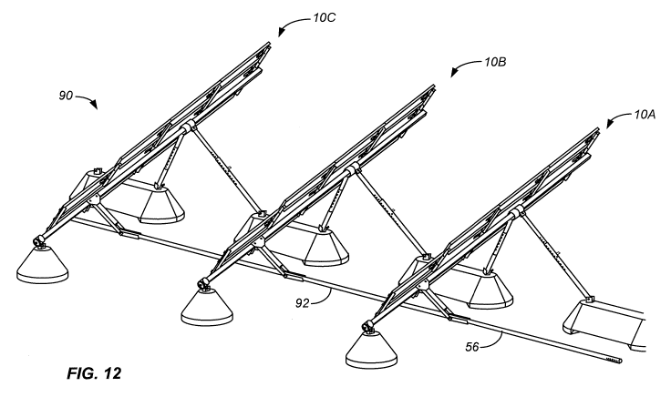
[0023] Fig. 12 illustrates the row of solar assemblies of Fig. 10 in evening,
generally west-
facing orientation;
[0024] Fig. 13 is an enlarged view of a portion of Fig. 12 showing the pivotal
connection of
drive element couplers to the outer end of the drive element of the middle
solar collector
assembly;
[0025] Fig. 13A illustrates an example in which four support struts are used
to support the
solar collector module assembly;
CA 02678786 2009-08-18
WO 2008/118518 PCT/US2008/051767
6
[0026] Fig. 13B illustrates a further example in which the solar collector
modules are bi-facial
solar collector modules and solar collector assembly includes a reflective
element to redirect solar
radiation back to the lower surface of the solar connector modules;
[0027] Fig. 13C is an enlarged view of a portion of the assembly of Fig. 13B
viewed from
above showing a gap between adjacent solar collector modules over the torque
member;
[0028] Figs. 14-17 show the structure of Fig. 1 in which a combiner box
assembly is used
along a row of the solar collector assemblies;
[0029] Fig. 18 is a bottom plan view of the solar collector module assembly of
Fig. 1 in a
storage and shipping orientation;
[0030] Figs. 19-22 illustrate a stack of the solar collector module assemblies
of Fig. 18
separated by spacer assemblies;
[0031] Figs. 23 and 23A are overall views showing a further example of a row
of solar
collector assemblies;
[0032] Fig. 24 is a view similar to that of Fig. 23A showing a still further
example of a row of
solar collector assembly;
[0033] Fig. 25-27 are front elevational, rear elevational and side elevational
views of the row
of solar collector assemblies shown in Fig. 23A;
[0034] Fig. 28 is an enlarged overall view of a tilt assembly for use with the
embodiments of
Figs. 23-27;
[0035] Fig. 29 is a rear elevational view of the tilt assembly of Fig. 28;
[0036] Fig. 30 shows a further example of a solar collector assembly
arrangement including a
stack of solar collector assemblies, similar to that of Fig. 19, mounted to a
shipping/storage skid;
[0037] Figs. 31 and 32 are enlarged views of the ends of the arrangement of
Fig. 30 with the
top solar collector assembly spaced apart to show detail;
[0038] Figs. 33 and 34 are enlarged partial end views of the upper and lower
portions of the
arrangement of Fig. 30;
[0039] Fig. 35 is an underside view of a solar collector assembly of Fig. 30
in the storage or
transportation configuration of Fig. 30;
[0040] Fig. 36 is an isometric view of the spacer element of Fig. 31;
[0041] Fig. 37 is an isometric view of the drive element of Fig. 31;
[0042] Fig. 38 is an end in view of the solar collector assembly arrangement
of Fig. 30
showing the use of a hold down straps at either end to help maintain the stack
of solar collector
module assemblies secured to the skid;
CA 02678786 2009-08-18
WO 2008/118518 PCT/US2008/051767
7
[0043] Fig. 39 is an isometric view showing the use of a lifting bar to remove
the upper solar
collector module assembly from the stack of solar collector module assemblies;
and
[0044] Figs. 40 and 41 are side and enlarged partial side views of the
structure of Fig. 39.
DESCRIPTION OF THE SPECIFIC EMBODIMENTS
[0045] The following description will typically be with reference to specific
structural
embodiments and methods. It is to be understood that there is no intention to
limit the invention
to the specifically disclosed embodiments and methods but that the invention
may be practiced
using other features, elements, methods and embodiments. Preferred embodiments
are described
to illustrate the present invention, not to limit its scope, which is defined
by the claims. Those of
ordinary skill in the art will recognize a variety of equivalent variations on
the description that
follows. Like elements in various embodiments are commonly referred to with
like reference
numerals.
[0046] One of the advantages accruing from some examples of the invention is
the ability to
install solar collector assemblies over uneven terrain without the need for
substantial site
preparation. This permits solar collector assemblies to be installed at
locations that otherwise
would not be economically feasible.
[0047] Fig. 1 illustrates a solar collector assembly 10 including broadly a
solar collector
module assembly 12 mounted above a support surface 14, typically the ground,
by a first support
16, sometimes referred to as south side support 16, and by a second support
18, sometimes
referred to as north side support 18. Solar collector module assembly 12
includes a frame 20
supporting a number of solar collector modules 22. As shown in Figs. 4 and 5,
frame 20 includes
a frame member 24, sometimes referred to as torque member 24, supporting
transversely oriented
rails 26. Solar collector modules 22 are secured to rails 26 by clips 27 (see
Figs. 6, 7A and 22) or
other mounting structure appropriate to the construction of the solar
collector modules. An
example of clips suitable for use with solar collector modules 22 having a
peripheral frame is
disclosed in U.S. Patent Application No. 11/681,972 filed 05 March 2007,
attorney docket
number PWRL 1044-2.
[0048] Fig. 5A illustrates an alternative example in which solar collector
module 22 is a
frameless module secured to rails 26 of frame 20 using an adhesive. The use of
a frameless solar
collector module can provide several advantages, including saving the cost of
solar collector
module frames, increasing the stack density (see Figs. 19-22) due to lower
overall height, and
helping to prevent theft because frameless modules can be adhered to the
substructure which
makes it difficult to remove the module without damaging it.
CA 02678786 2009-08-18
WO 2008/118518 PCT/US2008/051767
8
[0049] As shown in Fig. 6, south side support 16 includes a first surface
mount 28, sometimes
referred to as south base 28, resting on and substantially above support
surface 14. In appropriate
cases some surface preparation of support surface 14 may be necessary or
desirable to provide a
stable surface for base 28. South base 28 is an anchorless, ballast type base
designed to be
sufficiently heavy to secure the south end 30 of torque member 24 in place
without the need for
substantial excavation of the support surface, such as would be necessary if
base 28 were buried
within the support surface, or the need to otherwise anchor the south base to
support surface 14.
South base 28 is typically made of concrete.
[0050] Torque member 24 is pivotally secured to south base 28 by a south side
joint 34.
South side joint 34 includes a south bearing assembly 36 having an inner
bearing member 38
affixed to south end 30 of torque member 24 and an outer bearing member 40
rotatable about
inner bearing member 3 8. This permits torque member 24 to rotate or pivot
about a tilt axis 42
defined by the torque member. South side joint 34 also includes a south pivot
mount 44 securing
outer bearing member 40 of south bearing assembly 36 to south base 28 for
pivotal movement
about a generally horizontal south pivot axis 46. This permits tilt angle 32
to be changed. The
orientation of south pivot mount 44 relative to south base 28 can also be
adjusted about a vertical
axis. The ability to adjust the orientation of south pivot mount and the
ability of torque member
24 to pivot about tilt axis 42 and about south pivot axis 46 helps to
accommodate unevenness in
support surface 14 thereby helping to eliminate extensive preparation of
support surface 14 prior
to installation.
[0051] Referring now to Figs. 1, 8 and 9, north side support 18 includes
second surface
mounts 66, sometimes referred to as north bases 66, resting on support surface
14. North side
support 18 includes a support strut 70 extending from each north base 66 and
pivotally secured to
north end 68 of torque member 24 by a north bearing assembly 72. As with south
side support 16,
north bases 66 are anchorless, ballast type bases designed to be sufficiently
heavy to secure the
north end 68 of torque member 24, and therefore solar collector module
assembly 12, against
wind and other forces without need to excavate or otherwise anchor the north
bases to support
surface 14. North base 66 is typically made of concrete.
[0052] The required weight for south base 28 and each north base 66 will
depend upon
various factors including the size and configuration of assembly 12, expected
wind speeds,
expected wind directions, and tilt angle 32. For example, for solar collector
assemblies having a
surface area of about 9.3 to 37 square meters (100 to 400 sq. ft.) oriented at
a tilt angle 32 (see
Fig. 5) of 20 , each north base 66 may have a weight of at least 2270 kg (5000
lbs.) and each
south base 28 may have a weight of at least 680 kg (1500 lbs.).
CA 02678786 2009-08-18
WO 2008/118518 PCT/US2008/051767
9
[0053] One of the advantages of north side support 18 is that north base 66
can function as a
shared, unitary north base when used between adjacent solar collector
assemblies 10 in a row 90
of assemblies 10. In the example of Figs. 10-12, the north base 66 between
assembly 1 0A and
assembly l OB and between assembly 10B and assembly lOC are shared, unitary
north bases. This
is important because loads, in particular wind loads, on assemblies 10 are not
the same and are
typically constantly changing. Therefore, loads, in particular lateral loads,
exerted on assemblies
in the same row 90 can be distributed among the other assemblies in the row
through north
bases 66. Therefore, the total weight of all of the north bases 66 in row 90
can be less than if
north bases were not shared between adjacent solar collector assemblies 10
while making the
possibility of overturning solar collector assemblies 10 highly unlikely. In
other examples,
instead of using north base 66 as a shared base, each north base 66 would be
used with a single
solar collector module assembly 12; see Fig. lA. In addition, a combination of
the two can be
used in a single row 90 with only some of solar collector assemblies 10
sharing a north base 66.
[0054] Each north bearing assembly 72 is similar to south bearing assembly 36
and includes
an inner bearing member 74 affixed to torque member 24 and an outer bearing
member 76
rotatably mounted over inner bearing member 74 so to be free to pivot about
tilt axis 42. The
upper end of 78 of each support strut 70 is pivotally mounted to outer bearing
member 76 by a
clevis-type strut mount 80 so that support strut 70 can pivot about a strut
mount axis 82. The
lower end 84 of support strut 70, see Fig. 4, is pivotally mounted to north
base 66 by a north
pivot mount 86. North pivot mount 86 is substantially the same as south pivot
mount 44 and
permits support strut 70 to pivot about a generally horizontal axis
corresponding to south pivot
axis 46. In addition, north pivot mount 86 can be rotated about a generally
vertical axis to aid
securing support strut 70 to torque member 24 and north base 66. Support
struts 70 are also
variable length, telescoping struts. The pivotal connections between support
strut 70 and torque
member 24, the pivotal connections between support strut 70 and north base 66,
and the use of the
variable length, telescoping struts 70 enhances the ease of installation of
solar collector assembly
10 because exact placement of north bases 66 is not required nor must support
surface 14 be
extensively graded or otherwise prepared to accept the north bases. The
ability to place north and
south bases 66, 28 without substantial excavation, that is with only that
excavation required to
provide a stable support surface for the ballast-type north and south bases,
provides a significant
cost advantage during installation.
[0055] In some examples multiple support struts 70, four in the example of
Fig. 13A, can
extend from a single torque member 24 to a north base 66. This arrangement can
be especially
useful for larger solar collector module assemblies 12 that may be heavier and
may exert larger
CA 02678786 2009-08-18
WO 2008/118518 PCT/US2008/051767
wind loads on support struts 70. Bearing assemblies 72 are shown spaced apart
from one another
in the example of Fig. 13A. Some or all of bearing assemblies 72 may be
adjacent to one another
or spaced apart from one another whether two support struts 70 or three or
more support struts 70
extend from a single torque member 24.
[0056] Referring now to Fig. 1, solar collector module assembly 12 is pivoted
about tilt axis
42, thus allowing the assembly to follow the movement of the sun during the
day, by a tilt
assembly. Figs. 7, 7 A and 7B show one example of a tilt assembly 50 while
figures 27, 28 and
29 show another, and presently preferred, example of a tilt assembly 400.
[0057] Tilt assembly 50 includes a driver 52 connected by a drive rod 56 to a
torque arm type
of drive element 54 extending from torque member 24. The inner end 58 of drive
element 54 is
secured to torque member 24 and extends from the torque member generally
perpendicular to a
plane defined by solar collector modules 22. Drive element 54 includes a
clevis-type outer end 60
which receives the clevis-type distal end 62 of drive rod 56 with ends 60, 62
pivotally secured to
one another by a pivot element 64, typically a round pin secured by two roll
pins. Driver 52
causes drive rod 56 to move in a generally linear, generally horizontal
fashion; this movement
causes outer end 60 of drive element 54 to rotate about tilt axis 42 thus
allowing solar collector
modules 22 to generally follow the sun.
[0058] Driver 52 is mounted to a footing or foundation 65 which, like south
base 28 and north
base 66, is typically concrete and is heavy enough not to require burying
within the ground. As
shown in Fig. 7B, driver 52 is oriented at an angle 69 equal to tilt angle 32
to best accommodate
the motion of outer end 60 of drive element 54. Therefore, it is typically
desired that foundation
65 be generally horizontal. However, the need for foundation 65 to be
generally horizontal can be
eliminated by constructing tilt assembly 50 in a manner to eliminate this
requirement. For
example, the angular orientation between driver 52 and foundation 65 can be
made to be
adjustable.
[0059] Figs. 27, 28 and 29 illustrate a tilt assembly 402 comprising a driver
400 and drive
element couplers 92. Driver 400 is connected to and drives drive element
couplers 92. Drive
element couplers 92 extend to drive elements 54, see Fig. 13, of the solar
collector assembly 10
on either side of tilt assembly 402. Driver 400 includes a drive frame 406
including a base 408
adapted to be secured an appropriate foundation or other support, not shown.
The foundation
could be an aboveground structure or a fully or partially buried structure.
For example, base 408
could be bolted, welded or otherwise secured to a large, heavy steel plate
with, or without, rods or
spikes driven into the earth. Other examples for the foundation include a
screw-in foundation, a
CA 02678786 2009-08-18
WO 2008/118518 PCT/US2008/051767
11
vibration or pressure (or both) driven tube or tubes, and a ballasted vessel
filled with (typically
local) soil or gravel.
[0060] Drive frame 406 also includes a generally vertical post 410 and a
transversely
extending member 412 extending from the upper end of post 410 to create a
generally L-shaped
structure. Member 412 extends upwardly and outwardly at an angle to the
horizontal generally
equal to the inclination of tilt axis 42. A pair of support arms 414 extend
from either end of
member 412. A drive arm support 416 is mounted to the distal ends of support
arms 414 by
bearings 418. This permits drive arm support 416 to rotate about a drive arm
axis 420. Drive arm
axis 420 is arranged to be generally parallel to and generally laterally
aligned with pivot axes 42
of the solar collector assemblies 10 on either side of tilt assembly 402.
[0061] Driver 400 also includes a drive arm 422 extending from drive arm
support 416 and
connected to the clevis-type ends 94 of drive element couplers 92 at a drive
position 424. The
distance from drive position 424 to drive arm support axis 420 is termed
second distance 426.
Second distance 426 is equal to a first distance measured between pivot
element 64 and tilt axis
42 passing through the center of torque member 24; see Figs. 7 and 13.
[0062] Driver 400 also includes a drive arm driver 428 including a motor 430
connected to a
drive rod 432 by a gear arrangement 434. The gear arrangement 434 typically
uses a worm gear
reduction to a screw jack; however drive rod 432can also be driven by a
hydraulic pump and jack
or other actuation devices. The configuration of tilt assembly 402, and
especially drive frame
406, permits drive element couplers 92 to freely pass beneath a portion of the
drive frame. Drive
frame 406 accomplishes this in a cantilevered fashion using a single post 410;
however, drive
frame 406 could be otherwise configured, such as with a post 406 on both sides
of drive element
couplers 92, to provide this feature. Driver 400 also includes an enclosure
436 containing an
electronic controller used to control the actuation of motor 430 throughout
the day.
[0063] Tilt assembly 402 provides several advantages over tilt assembly 50.
When using tilt
assembly 50, certain forces, specifically non-horizontal forces acting on the
solar collector
module assemblies 12, are exerted by drive elements 54 on torque members 24 of
solar collector
assemblies 10 and increase towards the end of the row away from tilt assembly
50. Constructing
driver 400 so that the working length of drive arm 422, that is second
distance 426, is the same as
the working length of drive element 54, and arranging the location and
orientation of drive arm
support axis 420 to be aligned with tilt axes 42, causes drive arm 422 to go
through the same
motions as drive elements 54. Drive arm 422 thus minimizes the movement of
drive element 54;
this effectively eliminates this transfer of an increasing force from one
solar assembly 10 to the
adjacent solar assembly 10 when the solar assemblies and are all in line.
Placing driver 400
CA 02678786 2009-08-18
WO 2008/118518 PCT/US2008/051767
12
midway along row 90 of solar collector assemblies 10, which is a known
technique, allows a
single driver 400 to drive twice the number of solar collector assemblies 10
while using the same
strength drive element couplers 92 as the drive element coupler 92 needed
adjacent to drive rod
52 of the embodiment of Fig. 1. Placing driver 400 midway along row 90 of
solar collector
assemblies 10 also increases the number of solar collector assemblies 10 that
can be driven by a
single driver when the number of solar collector assemblies 10 that can be
driven by a single
driver is limited by the effects of thermal expansion.
[0064] The operation of drivers 52, 400 can be preprogrammed and adjusted to
the particular
location of the solar site. The location can be determined using, for example,
information from a
GPS device. Also, the operation of drivers 52, 400 can be controlled remotely
as a matter of
course. One benefit of remotely controlling all the solar collector assemblies
10 from a central
electronic controller is a reduction in the cost of the entire installation by
not needing a fully
functional electronic controller at every solar collector assembly 10, just a
simplified controller at
each assembly 10 and a fully functional central electronic controller. Another
benefit would be
that the operator would not need to physically go from assembly 10 to assembly
10 to do any sort
of maintenance on the electronic controllers associated with each assembly 10,
which can prove to
be very time consuming at large sites. Also, the user would not need to enter
site parameters for
every row; rather, it would be accomplished at the central electronic
controller. Solar collector
assemblies 10 are designed to be strong enough so as not to need to be tilted
to a safe tilt angle
(stowed) during high winds conditions. However, using a central electronic
controller would
facilitate stowing solar collector assemblies 10 during wind events.
[0065] Fig. 10 shows a row 90 of solar collector assemblies 10A, 10B, 10C
shown in a
morning, generally east-facing orientation while Figs. 11 and 12 illustrate
row 90 in noon time
and evening, generally west-facing orientations. Tilt assembly 50 includes
driver 52 and drive
rod 56 as is shown in Fig. 1. In addition, tilt assembly 50 includes drive
element couplers 92
coupling the outer ends 60 of drive elements 54 of assemblies 10A, 10B and of
assemblies 10B,
l OC. Fig. 13 is an enlarged view of a portion of assembly l OB of Fig. 12
illustrating the pivotal
connections between drive element couplers 92 and outer end 60 of drive
element 54. Drive
element couplers 92 are similar to drive rod 56 having one clevis-type end 94
and a plain,
cylindrical end 96 sized to fit within the clevis type end 94. Cylindrical end
96 has a number of
holes 98 to permit the effective length of couplers 92 to be changed. Other
techniques for
changing the length of couplers 92 may also be used. The use of the pivotal
connections at outer
ends 60 of drive elements 54 makes the alignment of assemblies 10 in a row 90
of assemblies
much less critical. This helps to permit rows 90 of assemblies 10 to be used
on uneven,
CA 02678786 2009-08-18
WO 2008/118518 PCT/US2008/051767
13
undulating or other support surfaces 14 that are not flat without the need for
extensive, and
expensive, site preparation.
[0066] A further example of a row 90 of solar collector assemblies 10 is
illustrated in Figs.
23, 23A and 25-27. Some of the differences between the example of Fig. 23 and
that shown in
Figs. 1 and 11 include the use of a different arrangement for solar collector
modules 22 and the
use of a tilt assembly 402 midway along the row 90 instead of a tilt assembly
50 at the end of the
row as shown in Fig. 1. The construction of, and advantages accruing through
the use of, tilt
assembly 402 has been discussed above with reference to Figs. 27, 28 and 29.
[0067] Solar collector assemblies 10 in Fig. 23 are considered to be a single
row 90; however,
assemblies 10 may also be considered to create two rows of solar collector
assemblies positioned
along generally the same East-West path or line. Although three solar
collector assemblies are
shown one each side of tilt assembly 402 in row 90, in practice many more
solar collector
assemblies will typically constitute a single row 90. Another difference
between row 90 of Fig.
23 and row 90 of Fig. 11 is the use of north bases 66 between adjacent solar
collector assemblies
but the use of smaller north bases 66A, similar to south bases 28, at the ends
of the rows and
located in the gap 404 between assemblies 10 on either side of driver 400. It
has been found that
it is typically not necessary to use the larger north bases 66 when only a
single support strut 70 is
connected to the north base.
[0068] Fig. 24 is a view of an example of a row 90 of solar collector
assemblies 10 similar to
that of Fig. 23A but having a somewhat different pattern of solar collector
modules 22. The
particular choice of the pattern or arrangement of solar collector modules 22
will typically depend
on maximizing the amount of PV on each solar collector module assembly 12
while (1) staying
within the size limitations of the mode of transportation, such as in a
container, on a truck or by
rail, (2) staying within appropriate electrical limitations, and (3)
maintaining integer fractions of
string lengths. String length is measured by the number of solar collector
modules 22 needed to
provide a desired electrical output. Integer fractions of string lengths means
that if a desired
string length is X, but you cannot fit that many on a solar collector module
assembly 12 because
X is too large, then the string length of each assembly 12 should be X/2 or
X/3 and so on, so that
assemblies 12 can be easily wired together in the field. In addition, a string
length can be too
small so that you could have multiple strings on one solar collector assembly
10.
[0069] Figs. 13B and 13C illustrate a further example in which solar collector
modules 22 are
bifacial modules. That is, they are constructed so that sunlight striking both
the upper surface 276
and the lower surface 278 of modules 22 can be transformed into energy. To
increase the amount
of solar radiation striking lower surface 278, a reflective element 279 in the
form of a sheet or tarp
CA 02678786 2009-08-18
WO 2008/118518 PCT/US2008/051767
14
is positioned below solar collector module assembly 12. Reflective element 279
reflects sunlight
that would otherwise be absorbed by the ground towards lower surface 278.
Other types of
reflective elements 279, such as a sheet of stiff or flexible metal or a sheet
of painted plywood,
may also be used. In addition, support surface 14 may be such as to permit a
reflective element
279 to be applied directly to support surface 14; for example reflective
element 279 may be in the
form of a layer of white gravel or a layer of paint. Reflective element 279
may have the same or a
different shape from that illustrated in Fig. 13B and may be sized larger or
smaller than that
illustrated in Fig. 13B. As shown best in Fig. 13C, solar collector modules 22
are spaced apart
from one another to define a gap 281 between the modules above torque member
24. Gap 281
between modules 22 is provided to help ensure that torque member 24 does not
shade lower
surfaces 278 of the modules when light is reflected back towards lower
surfaces 278 by reflective
element 279.
[0070] Figs. 14-17 illustrate another example which uses a combiner box
assembly 280 along
each row of solar collector assemblies 10. Wires from each solar collector
assembly 10 pass
along drive element 54 and along drive element couplers 92 until reaching
combiner box
assembly 280. The wires, not shown in Figs. 14-17, pass through an opening,
not shown, in drive
element coupler 92, into the open end 282 of a flexible hose 284, through
flexible hose 284 and
into combiner box 286. The proper movement of hose 284 is aided by the use of
tray 287 which
helps keep hose 284 from tangling, binding or reducing the minimum wire bend
radius as drive
element coupler 92 moves during the day. As shown in Fig. 17, the angular
orientation of hose
284 is such as to generally lie in a plane parallel to drive element 54.
[0071] It is preferred that solar collector module assemblies 12 be
constructed to minimize the
number of separate pieces that must be assembled at the solar site. It is also
preferred that solar
collector module assemblies 12 be storable and transportable in a compact
configuration with
minimal packing material. Figs. 18-26 illustrate one way of achieving a
compact storage and
transport configuration while Figs. 30-41 illustrate another, presently
preferred, way of doing so.
The Figs. 18-26 example will be discussed first, followed by a discussion of
the Figs. 30-41
example.
[0072] Fig. 18 illustrates a solar collector module assembly 12 in a shipping
and storage
orientation with support struts 70 arranged to lie parallel to frame 20 and
solar collector modules
22 and also generally parallel to torque member 24. This is achieved by
pivoting support struts 70
about axes 82 and also by rotating the support struts about tilt axis 42 with
outer bearing member
76 rotating around inner bearing member 74. Support struts 70 are temporarily
secured in this
shipping and storage orientation by, for example, using bailing wire to secure
support struts 70 to
CA 02678786 2009-08-18
WO 2008/118518 PCT/US2008/051767
torque member 24. In addition, drive element 54 is temporarily mounted to
torque member 24 so
to lie generally parallel to frame 20 and solar collector modules 22 with the
mounting plates 288
located on either side of torque member 24 as shown in Fig. 18.
[0073] Figs. 19 and 20 illustrate the assembly of a stack 290 of solar
collector module
assemblies 12 with a completed stack shown in Figs. 21 and 22. The south end
30 of torque
member 24 has a vertical opening 292. A first spacer assembly 294 is used to
separate and
support adjacent assemblies 12 through the use of a spacer tube 296. Spacer
tube 296 has a
reduced diameter portion 298 and a full diameter portion 300. Reduced diameter
portion 298 is
sized to fit within opening 292; however full diameter portion 300 is
oversized relative to opening
292. A rod 302 extends through each of the spacer tubes 296 and openings 292
in the stack 290
and is secured at each end with a nut 304 and washers 306. A threaded base
member 308 is used
at the bottom of the stack 290 to support the stack on a support surface. A
lifting eye 310 is
secured to the upper end of rod 302 and is used to aid moving stack 290. A
similar spacer
assembly 294 is used at the other end of stack 290.
[0074] A second spacer assembly 314 is used between, typically midway between,
first spacer
assemblies 294. Second spacer assembly 314 includes a pair of T-shaped
supports 316 positioned
beneath each assembly 12. Each T-shaped support 316 includes a base 318 and a
center element
320 extending upwardly from a central portion of base 318. T-shaped supports
316 are used to
separate and support adjacent assemblies 12. As shown in Fig. 20, rails 26 are
U-shaped with
downwardly extending legs 322 connected by a bight 324. There is a gap 326
between adjacent
modules 22 at rails 26. Base 318 is sized to fit within gap 326 and rest on
rails 26. Center
element 320 fits between legs 322 and rests against bight 324 of rail 26 so
that the weight of an
overlying assembly 12 is transferred to frame 20 of the underlying assembly
12. T-shaped
supports 316 are also used beneath the bottommost assembly 12 for supporting
the stack 390 on a
support surface, which may be, for example, provided by conventional pallets,
a custom full-
length pallet, the bed of a transport vehicle, or a loading dock. Stack 290
may be lifted and
moved using, for example, a forklift engaging one or more palettes (not shown)
supporting stack
290 or a crane using lifting eyes 310.
[0075] In this example some of the weight of overlying assemblies 12 is
transferred to the
underlying assemblies 12 through torque members 24 and spacer tubes 296. If
desired, spacer
tubes 296 could be configured so that the weight of overlying assemblies 12
would be transferred
directly to underlying spacer tubes 296, not through torque members 24.
[0076] Upon manufacture, solar collector module assemblies 12 can be placed in
the shipping
and storage orientation of Fig. 18 and stacked as shown in Figs. 19-22 using
first and second
CA 02678786 2009-08-18
WO 2008/118518 PCT/US2008/051767
16
spacer assemblies 294, 314. The installation site is determined. Stack 290 of
assemblies 12 can
be transported in the stacked configuration to the installation site. The
appropriate weights for
south bases 28 and north bases 66 are determined. Ballast-type south and north
bases 28, 66 are
relatively simple in construction and are typically manufactured at or close
to the installation site
to reduce shipping costs. South and north bases 28, 66 are placed on the
ground, or other support
surface, at the installation site. South bases 28 are typically placed at
spaced apart positions on a
generally East-West line. North bases 66 are also typically placed at spaced
apart positions on a
generally East-West line. Very little, if any, site preparation needs to be
made when using ballast-
type bases 28, 66 because the weight of ballast-type bases 28, 66 eliminates
the need to bury all or
part of the base within the ground, and the design of the system allows for
use on irregular, rough,
or undulating terrain. Assemblies 12 or then removed from stack 290 and
prepared for being
secured to south and north bases 28, 66. To do so drive element 54 is bolted
to torque member 24
to its use position shown in Fig. 7. South side joint 34 at south end 30 of
torque member 24 is
secured to south pivot mount 44 at south base 28. Support struts 70 are
pivoted downwardly and
outwardly using bearing assembly 72 and strut mount 80; see Figs. 8 and 9. The
length of each
support strut 70 is adjusted to position solar collector module assembly 12 at
tilt angle 32,
typically 20 , and to accommodate the position, height and orientation of the
north bases 66 to
which the support struts are attached. As shown in Fig. 4, in the disclosed
example this is
accomplished using a pin type member 328 passing through a hole 330 in a lower
telescoping
section 332 and one of several holes 334 in an upper telescoping section 336.
Finer length
adjustments can be provided by, for example, using a threaded insert at one or
both ends of
support strut 70 through which a pin, bolt or other pivot member, such as
pivot member 338,
passes. In some situations it may be necessary to extend the length of support
strut 70 to a length
greater than can be accommodated by telescoping sections 332, 336; in such
situations strut
extensions, not shown, may be used to accommodate the extra length needed.
North pivot mounts
86, which are attached to north bases 66, can rotate about a generally
vertical axis to become
aligned with the associated support strut 70. Lower end 84 of each support
strut 70 is pivotally
secured to north pivot mounts 86 by a bolt or other pivot member 338.
[0077] The determination of the weight for south bases 28 and north bases 66
can be made to
be site-specific based upon the size and configuration of assemblies 12 or can
be made based
upon typical configurations for assemblies 12 and expected wind loads. The
weight
determination can be made by the final user or installer or by the manufacture
of assemblies 12.
One typical way for determining the weight of south and north bases 28, 66 is
to provide the user
or installer guidelines so that for a particular range of surface areas for
assembly 12 oriented over
CA 02678786 2009-08-18
WO 2008/118518 PCT/US2008/051767
17
a particular range of tilt angles, recommended weights for south and north
bases 28, 66 can be
provided for different ranges of expected wind speeds. Alternatively, the
manufacturer can
provide the user or installer with recommended weights for south and north
bases 28, 66 based
upon information for the particular installation.
[0078] Fig. 30 shows an example of a solar collector assembly arrangement 450
including a
stack 452 of solar collector module assemblies 12, similar to the stack of
Fig. 19, mounted to a
shipping/storage skid 454. Skid 454 includes a generally rectangular base 456
and an upwardly
extending stabilizer bar 458. Skid 454 is designed to permit solar collector
assembly arrangement
450 to be lifted and transported using a number of methods, such as forklifts
or overhead cranes.
Skid 454 may have other configurations and may include, for example,
stationary or retractable
wheels for particular installations.
[0079] Solar collector module assembly 12 is similar to assembly 12 shown in
Figs. 1-13 and
18. One of the differences is that rails 26 of frame 20 are spaced apart from
the edges of solar
collector modules 22. This can be seen by comparing Fig. 35 with Fig. 18.
Also, instead of using
clips 27 along the edges of solar collector modules 22, see Fig. 6, rails 26
are secure in to the
underside of solar collector modules 22 using an appropriate fastener 455,
such as screws. Other
techniques for securing solar collector modules 22 to frame 20, including the
use of adhesives
with or without mechanical fasteners can also be used.
[0080] Solar collector module assemblies 12 are stacked one on top of another
using spacer
elements 466, see Figs. 31, 32 and 36, and through the use of drive element 54
as a stabilizer
when solar collector module assemblies 12 are in a storage or transportation
configuration, such
as in Figs. 30 and 39. Torque members 24 have holes 468, see Fig. 31, formed
therein for receipt
of the reduced-size ends 470 of spacer element 466. Holes 468 are located at
each end of torque
member 24 as well as, in this example, along the length of torque member 24 at
a four corner
junction 472 of adjacent solar collectors 22. The X cross-sectional shape of
spacer element 466
provides good strength while permitting solar collectors 22 to be mounted
close to one another.
The weight of overlaying assemblies 12 is transferred, through torque member
24, to frame 20 of
the underlying assemblies 12 so the solar collectors 22 do not need to support
the weight of
overlying assemblies 12. Fig. 32 also shows the use spacer elements 467 that
can also be placed
at a four corner junction. Spacer elements 467 are flat rectangular members
having cutouts 469 at
opposite ends sized for receipt of torque members 24.
[0081] Drive element 54 of Figs. 31 and 37 is substantially the same as drive
element 54 of
Fig. 7 with the following distinctions. Drive element 54 of Fig. 37 includes a
pair of plates 474
having holes 476 formed therein. Plates 474 are separated by distance slightly
larger than the
CA 02678786 2009-08-18
WO 2008/118518 PCT/US2008/051767
18
width of torque member 24, which has a square cross-sectional shape. This
permits drive element
54 to be placed in a use orientation, such as shown in Fig. 7, with the drive
element extending
generally perpendicular to the tilt axis 42 defined by torque member 24 and a
right angle to a
plane formed by modules 22. Quick release fasteners, bolts, or other suitable
fasteners can be
used to secure drive element 54 to torque member 24 by aligning holes 476 with
appropriately
positioned holes 478 (see Fig. 31) formed in torque member 24.
[0082] Drive element 54 of Fig. 37 also includes an outer tubular element 480
and an inner
tubular element 482 extending outwardly from plates 474. With drive element 54
in the storage
or transportation orientation of Figs. 31 and 35, that is with drive element
extending radially
outwardly from tilt axis 42 defined by torque member 24 and generally parallel
to a plane defined
by modules 22, the drive element can be secured to torque member 24 in the
same manner as
when in the use orientation, that is using bolts or other fasteners passing
through appropriately
formed holes in torque member 24. While in the use orientation it may be
desirable to use bolts to
secure drive element 54 to torque member 24, it may be desirable to use quick
release fasteners to
facilitate setting up the system on site. The outer end 60 of drive element 54
is secured to
stabilizer bar 458 using bolts, quick release fasteners, or other appropriate
means. The length of
inner tubular element 482 plus the thickness of plate 474 is chosen to be
equal to the height of the
large diameter portion 484 of spacer element 466 so to permit weight to be
properly transferred
between torque members 24 at the location of drive elements 54. In the storage
or transportation
orientation of Figs. 31 and 37, drive element 54 acts as a stabilizer arm 54
to not only transfer
weight between torque members 24 but also to provide lateral stability to
assemblies 12 and
effectively prevent assemblies 12 from rotating or twisting about their torque
members 24.
[0083] Fig. 38 is an end in view of the solar collector assembly arrangement
450 of Fig. 30
showing the use of a hold down strap 486 at one end to help maintain the stack
of solar collector
module assemblies 12 secured to skid 454. Strap 46 passes through a hollow
frame number 488
of base 456 and extends over the torque member 24 of the uppermost solar
collector module
assembly 12. Hold down strap 486 includes a tensioning device 487 to allow the
user to provide
proper tension to strap 486. A similar strap is used at the other end of base
456.
[0084] Figs. 39-41 show the use of lifting apparatus 490 to aid in lifting a
solar collector
module assembly 12 to either create a stack of assemblies 12 or to remove an
assembly 12 from a
stack of assemblies 12, typically at an installation site with the aid of a
crane, forklift or other
mechanical lifting apparatus. Lifting apparatus 490 includes a lifting bar 491
having a pair of
stabilizing bars 492 secured to the bottom of bar 491. Lifting apparatus 490
also has lifting hooks
at both ends and a lifting line 494 extending outwardly from lifting bar 491.
Lifting apparatus
CA 02678786 2009-08-18
WO 2008/118518 PCT/US2008/051767
19
490 also includes a lifting eye adapter 495 that can be secured to either end
of torque member 24,
typically using a bolt or a quick release fastener, not shown, passing through
holes 496, 497
formed in torque member 24 and adapter 495, respectively.
[0085] The above descriptions may have used terms such as above, below, top,
bottom, over,
under, et cetera. These terms are used to aid understanding of the invention
are not used in a
limiting sense. The directions north and south have been used assuming the
installation site is in
the Northern Hemisphere. The more generic terms polar for north and equator or
equatorial for
south can be used to cover installation sites in both the Northern Hemisphere
and the Southern
Hemisphere.
[0086] Modification and variation can be made to the disclosed embodiments
without
departing from the subject of the invention. For example, torque member 24 may
have a variety
of cross-sectional shapes including round and square, may have a partially or
fully solid interior,
may be made of one or more materials, and may have its various structural
features vary along its
length. Torque member 24 and rails 26, which act as a support or frame for
solar collector
modules 22, could be replaced by other solar collector support structure, such
as a rigid
rectangular platform. Therefore, tilt assembly 50 could be secured to
structure other than torque
member 24. The solar collector support structure could be mounted so to tilt
not about a fixed tilt
axis 42 but, for example, about a range of instantaneous tilt axes.
[0087] Any and all patents, patent applications and printed publications
referred to above are
incorporated by reference.