Note: Descriptions are shown in the official language in which they were submitted.
CA 02678838 2009-08-20
WO 2008/103343
PCT/US2008/002166
-1-
HINGED OVERCAP FOR A CONTAINER
Related Applications
[0001] The present application claims the benefit of provisional
application serial no.
60/903,211, filed March 23, 2007.
Field of the Invention
[0002] The present invention relates generally to a cap for a container.
Background of the Invention
[0003] Often, containers that store perishable products, such as food,
include a removable
membrane sealed to the rim of the container. The membrane is used to help
prevent the
transfer of oxygen, moisture and other contaminants into the container. The
membrane also
provides a measure of tamper evidency. When a consumer buys the container, the
membrane
is removed and discarded. The container can then be used to dispense the
product.
[0004] It is known to include an overcap to provide access to the product
retained within
a container. For example, US 4,718,567 to LaVange shows an overcap for an open-
mouthed
container. The cap has two annular skirts, with one skirt including an
inwardly projecting rib
that engages a rim on the container to retain the cap on the container. The
inner skirt is sized
to fit within the open end of the container, positioning the rim between the
two skirts. The
cap also includes a hinged flap that selectively closes an opening in the
overcap, which forms
the opening for the container.
[0005] US 2005/0236465 to Stevens shows an overcap with an outer annular
skirt
adapted to engage the rim of a container. A hinge is provided across a top
panel of the
overcap to allow a portion of the top panel to be selectively rotated with
respect to the
remaining portions of the top panel to provide access to the product within
the container. The
skirt portion includes an inwardly extending rib that engages the container
rim to secure the
overcap to the container. The hinged portion of the overcap can be opened by
moving the rib
on the hinged portion over the rim of the container.
CA 02678838 2009-08-20
WO 2008/103343
PCT/US2008/002166
-2-
[00061 US 3,412,890 to Rich shows an overcap for a container having a
hinged portion,
an inner skirt and an outer skirt. The skirts are sized to engage opposite
sides of the container
rim. When the hinged portion of the cap is opened, the inner and outer skirts
are moved away
from the rim of the container. The inner skirt includes an outwardly
projecting rib that
engages a matching groove on the inside surface of the rim of the container.
100071 US 2005/0167430 to Varadarajan shows an overcap for a container
having an
annular skirt with a pair of inwardly projecting ribs that form upper and
lower grooves for
receipt of the container rim therein. The overcap can be positioned in a first
position, with
the rim of the container engaged within the relatively lower groove, to retain
a sealing
membrane on the rim of the container and with the membrane being spaced from
the inside
surface of the overcap. In a second position, the container rim is engaged
within the
relatively upper groove on the overcap and the container is sealed by the
engagement of the
container rim with the skirt and the inside surface of the top panel of the
overcap.
Summary of the Invention
[0008] An overcap for a container is provided that engages the container in
two alternate
positions and provides access to the inside of the container using a movable
flap portion. The
overcap includes a hinge that divides the cap into first and second flap
portions. At least one
of the flap portions is moveable away from the container rim to provide access
to the interior
of the container. The flap portions each include a first skirt extending
downward from the
outer edge of the flap. The first skirt has an inwardly projecting lower rib
and an inwardly
projecting upper rib formed on the inside surface of the skirt. The ribs
create a relatively
lower groove between the two ribs and an upper groove between the upper rib
and the bottom
of the flap portions. The grooves are sized to engage an upper rim or similar
feature on the
container.
[0009] The flap portions also include a second skirt extending downward
from the bottom
of the flap. The second skirt is positioned radially inward of the first skirt
and is relatively
shorter than the first skirt. The lower edge of the inner skirt is positioned
relatively above the
container rim when the overcap is retained in the lower groove or first
position. In a second
position, with the overcap in the second position, the container rim is
sandwiched between
the first and second skirts, providing retention of the overcap on the rim.
CA 02678838 2009-08-20
WO 2008/103343
PCT/US2008/002166
-3-
Brief Description of the Drawings
[0010] There is shown in the drawings a number of embodiments that are
presently
contemplated. Reference should be made to the description of these embodiments
as well as
the claims that follow for defining the scope of the invention.
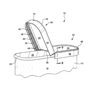
[0011] Fig. 1 shows an isometric view of a container and overcap
combination, with the
cap in a first position, closing the open mouth of the container.
[0012] Fig. 2 shows a partial isometric view of the container and overcap
combination,
with the cap in the first position and a flap portion opened, exposing a
sealed membrane
positioned across the mouth of the container.
[0013] Fig. 3 shows a partial cross-section of the container and overcap as
taken along
line 3-3 in Fig. 2.
[0014] Fig. 4 shows a partial isometric view of the container and overcap
combination,
with the cap in a second position and the flap portion opened, exposing the
open mouth of the
container.
[0015] Fig. 5 shows a partial cross-section of the container and overcap as
taken along
line 5-5 in Fig. 4.
[0016] Fig. 6 shows a partial isometric view of the container and overcap
with an
alternate upper rim design.
[0017] Fig. 7 shows a partial cross-section of the container and overcap
combination,
with the cap in the first position, as taken along line 7-7 in Fig. 1.
[0018] Fig. 8 shows a partial cross-section of the container and overcap
combination
similar to Fig. 7, with the cap in the second position.
Detailed Description of the Drawings
[0019] In the drawings, where like numerals identify like elements, there
is shown a
container and overcap combination, which is generally referred to by the
numeral 10. In Fig.
1, the container 10 includes a container body 12 with the overcap 14
positioned thereon. The
container body 12 comprises a hollow reservoir defined by a bottom wall (not
shown), an
annular upstanding side wall 16 and an open-mouth 18 (see Fig. 4). An annular,
upper rim 20
is defined at the upper end of the side wall 16. A removable membrane 22 is
attached to the
rim 20 (see Fig. 2) to seal the reservoir and contents of the container body
12. As illustrated
in Fig. 3, the upper rim 20 of the container 12 is formed by a rolled portion
of the sidewall 16
CA 02678838 2014-05-02
-4-
of the container body 12. However the rim may have a different form or may be
made by a
separately attached element, such as a crimped bead (not shown).
[0020] Referring to Fig. 2, the overcap 14 as illustrated includes a top
panel 24 divided
into two portions by a hinge 26. The hinge 26 bisects the panel 24 into a
first flap portion 28
and a second flap portion 30, with one or both of the flaps being movable
about the hinge 26.
The overcap 14 is preferably integrally molded with the hinge 26 formed as a
living hinge. In
Fig. 2, the first flap portion 28 is shown in the open position, exposing the
top of the
container body 12. As illustrated, the sealing membrane 22 is affixed to the
container rim 20
and covers the mouth 18 of the container 12.
[0021] The two flap portions 28, 30 each include a first skirt 34 extending
downward
from the outer edge of the panel 24. A break 35 (see Fig. 1) is formed in the
first skirt 34
along the line of the hinge 26 so that the relevant portions of the skirt 34
associated with each
flap 28, 30 can be separated, when one flap is pivoted about the hinge 26. A
frangible bridge
or an overlap of the edges may be provided along the break 35 to create a 360
degree surface
surrounding or encircling the rim 20 of the container 12. As best seen in the
cross section of Fig. 3, the
first skirt 34 includes an inwardly projecting first or lower rib 36 and a
second or relatively
upper rib 38, formed on the inside surface of the wall of the skirt 34. The
ribs 36, 38 define a
relatively lower groove 40 between the two ribs and an upper groove 42 between
the upper
rib 38 and the bottom surface of the top panel 24.
[0022] The lower groove 40 and upper groove 42 are sized to engage the
upper rim 20 of
the container body 12. The lower groove 40 and upper groove 42 are not
required to have
identical length or depth. For example, it may be appropriate for the membrane
22 to drape
over the upper rim 20, thereby increasing the overall width of the upper rim
20. As such, the
lower groove 40 and the upper groove 42 are likely dimensioned differently to
provide an
optimum fit for the membrane 22, when present. The upper groove 42 is
preferably
dimensioned slightly smaller than the lower groove to optimize the fit and to
ensure freshness
of the product within the container body 12, when the overcap 14 is in the
second position.
100231 A second skirt 44 is formed on the bottom surface of the top panel
24, radially
inward from the first skirt 34. The second skirt 44 extends downwardly from
the top panel 24
to a position substantially equal to the bottom of the upper groove 42. The
second skirt may
contact the membrane 22 when the rim is in the first position to help
stabilize the overcap 14.
However, in some instances, during shipment of the container with a sealed
membrane, the
CA 02678838 2009-08-20
WO 2008/103343
PCT/US2008/002166
-5-
membrane will tend to rise or form a dome, due to the difference in ambient
pressure and the
internal pressure within the container. Thus, the relative position of the
first groove and the
lower edge of the inner skirt may be adjusted such that the doming of the
membrane does not
move the overcap or in extreme situations force the overcap off the container
rim.
[0024] The second skirt 44 is inwardly spaced from the first skirt 34 such
that the upper
rim 20 of the container body 12 is preferably engaged between the two skirts
34, 44 when the
rim 20 is positioned in the upper groove 42 (see Fig. 5). A gap may be
provided in the
second skirt 44, adjacent the hinge 26, so that the two sections of the second
skirt 44a, 44b
may also pivot about the hinge 26 when one flap portion is opened.
Alternatively, as
particularly shown in Fig. 7, the seam 45 between the two sides 44a, 44b of
the inner skirt 44
may include an abutting surface or an overlapping edge, similar to break 35 in
the outer skirt
34.
[0025] As illustrated, an upper rib 46 is formed on the outside surface of
the top panel 24.
The upper rib 46 facilitates stackability of the overcaps 14 prior to assembly
with the
container body 12. The upper rib 46 may also serve to stabilize the stacking
of overcap and
container combinations 10, with the bottom wall (not shown) of the container
body 12
forming a rim that fits either inwardly or outwardly of the upper rib 46 when
two containers
are stacked on top of one another. The upper rib 46 may also stiffen the flap
portions 28, 30
and assist in the handling of the overcap 14 during opening and closing. Other
structures
may be added to the surface of the top panel 24 to stiffen the panel or for
other purposes.
[0026] Referring again to Figs. 2 and 3, the overcap 14 is shown in the
first position,
where the upper rim 20 engages the lower groove 40 on the inside surface of
the first skirt 34.
In this first position, the overcap 14 is affixed to the container 12. As
illustrated, the second
or inner skirt 44 is spaced from the removable membrane 22. However, the skirt
44 may
contact the membrane, although preferably does not pierce the surface of the
membrane.
Thus, in the first position, the container body 12 is in a sealed condition
and the overcap 14 is
retained on the rim of the container body 12, within the first or lower groove
40. Once the
container 10 is ready for use, the overcap 14 can be separated from the
container body 12 and
the membrane 22 removed from the rim 20 -- exposing the mouth 18 and contents
in the
reservoir formed by the container body 12. The overcap 14 is then placed back
onto the rim
20 of the container body 12 and engaged within the second groove 42 on the
inside surface of
the first skirt 34.
CA 02678838 2009-08-20
WO 2008/103343
PCT/US2008/002166
-6-
[0027] Referring now to Figs. 4 and 5, the overcap 14 is shown in the
second position
with the upper rim 20 engaged within the second or upper groove 42 and the
second skirt 44
positioned inside of the rim 20 and engaging the inside surface of the
sidewall 16. When the
rim 20 in positioned in the second groove 42, additional retention force is
created by the
outside or first skirt 34 and the inside or second skirt 44, thus stabilizing
the overcap 14 on
the rim 20. Also, while in the second position, the first flap portion 28 and
its associated
skirts 34, 44 can be rotated about the hinge 26 to open the container, while
the second flap
portion 30 is maintained affixed to the container rim 20. Preferably, both
flap portions 28, 30
are designed to open. Thus, the second flap portion 30 can be opened about the
hinge 26,
while the first flap potion 28 maintains the overcap 14 affixed to the
container rim 20.
[0028] In Fig. 6, there is shown an alternate form of the container 10'. In
this
embodiment, the container body 12 includes an attached rim structure 21 at the
upper end of
the side wall 16. The rim structure 21 includes a flange that is attached to
the side wall 16
and that includes a formed rim 20'. As illustrated, the rim structure 21 is
affixed to the outer
surface of the container body 12. However the depending flange may also be
affixed to the
inside surface of the sidewall 16, with the upper edge captured under the rim
portion 20'.
Affixing the rim structure 21 as shown can be accomplished by an adhesive or
any alternate
mechanical structure. The rim structure and container may also be integrally
formed.
[0029] Figs. 7 and 8 illustrate the relative position of the two portions
34a, 34b of the
outer skirt 34 and the two portions 44a, 44b of the inner skirt with respect
to the rim 20 of the
container body 12. In Fig 7, the overcap 14 is in the first or upper position,
with the
membrane 22 sealed to the upper surface of the rim 20. The two portions 44a,
44b of the
inner skirt 44 abut one another at seem 45. Directly behind the inner skirt 44
is the break line
35 of the outer skirt 34, which separates the two portions 34a, 34b of the
outer skirt 34. In
Fig 8, the membrane has been removed and the overcap 14 moved to the second
position,
with the rim 20 positioned within the second or upper groove 42, above the
second rib 38.
Preferably, the two portions 44a, 44b of the inner skirt 44 abut or overlap
one another at the
seam 45. This configuration serves to form at least a partial seal along the
inside of the
sidewall of the container body, adjacent the rim 20. Thus, when the overcap 14
is closed, the
contents of the container 10 are more readily preserved.
[0030] The above features of the storage container and overcap combination
can be made
of any suitable material including but not limited to paper, plastic, metal or
wood. Further,
CA 02678838 2015-03-02
-7-
other variations and modifications of the structure as illustrated and
discussed herein will be
apparent to those skilled in the art upon reading the present description. The
above description
and accompanying drawings are only illustrative of exemplary embodiments,
which can
achieve the features and advantages of the present invention. It is not
intended for the scope of
the claims to be limited to the exemplary or preferred embodiments set forth
in the examples,
but should be given the broadest interpretation consistent with the
description as a whole.
=
=