Note: Descriptions are shown in the official language in which they were submitted.
CA 02678893 2013-04-19
METHODS TO CONTROL CELL MOVEMENT IN HOLLOW FIBER
BIOREACTORS
Background
Human stem cells, which have been expanded in culture from a small
amount of donor cells, can be used to repair or replace damaged or defective
tissues and have broad clinical applications for treatment of a wide range of
diseases. Recent advances in the area of regenerative medicine demonstrate
that
stem cells have unique properties such as self-renewal capacity, the ability
to
maintain the unspecialized state, and the ability to differentiate into
specialized cells
under particular conditions.
As an important component of regenerative medicine, the bioreactor or cell
expansion system plays a role in providing optimized environments for cell
growth
and expansion. The bioreactor provides nutrients to the cells and removal of
metabolites, as well as furnishing a physiochemical environment conducive to
cell
growth in a closed, sterile system. Cell expansion systems can be used to grow
other types of cells as well as stem cells.
Many types of bioreactors are currently available. Two of the most common
include flat plate bioreactors and hollow fiber bioreactors. Flat plate
bioreactors
enable cells to grow on large flat surfaces, while hollow fiber bioreactors
enable
cells to grow either on the inside or outside of the hollow fibers.
If hollow fiber bioreactors are used, it is desirable to load cells into the
hollow
fibers in such a way that the cells are properly distributed throughout the
length and
width of the hollow fibers, not just at one end. It is to such aspects that
the present
invention is directed.
1
CA 02678893 2009-08-20
WO 2008/109668
PCT/US2008/055904
BRIEF DESCRIPTION OF THE FIGURES
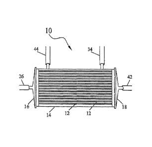
FIG. 1 is a schematic view of a bioreactor useful in this invention.
FIG. 2 is a flow diagram of a cell expansion system which may be used with the
present
invention.
- 2 -
CA 02678893 2014-08-01
SUMMARY OF THE INVENTION
This invention is directed toward a method for moving cells in a hollow fiber
bioreactor wherein the hollow fibers have an intracapillary space and an
extracapillary space.
The method includes the steps of loading cells into the intracapillary space,
and flowing a
fluid into one of the intracapillary space or extracapillary space at a flow
rate pressure to
move and distribute the cells along a length of the fibers.
This invention is also directed toward a method for moving unpurified whole
bone
marrow cells in a cell expansion system, the method comprising:
providing a hollow fiber bioreactor, the hollow fiber bioreactor comprising
hollow
fibers, wherein the hollow fibers comprise an intracapillary space and an
extracapillary
space;
providing an extracapillary media bag fluidly connected to the extracapillary
space of
the hollow fiber bioreactor, wherein the extracapillary media bag comprises
extracapillary
fluid;
providing an intracapillary media bag fluidly connected to the intracapillary
space of
the hollow fiber bioreactor, wherein the intracapillary media bag comprises
intracapillary
fluid;
pumping extracapillary fluid from the extracapillary media bag into the
extracapillary
space of the bioreactor using a first pump;
pumping intracapillary fluid from the intracapillary media bag into the
intracapillary
space of the bioreactor using a second pump;
providing an intracapillary circulation loop comprising a length of tubing
fluidly
connecting an outlet port of the intracapillary space to an inlet port of the
intracapillary space
such that the intracapillary fluid can be circulated through the
intracapillary space via the
intracapillary circulation loop;
providing a third pump to pump intracapillary fluid through the intracapillary
circulation loop;
providing an extracapillary circulation loop comprising a length of tubing
fluidly
connecting an outlet port of the extracapillary space to an inlet port of the
extracapillary
- 3 -
CA 02678893 2014-08-01
space such that the extracapillary fluid can be circulated through the
extracapillary space via
the extracapillary circulation loop;
providing a fourth pump to pump extracapillary fluid through the
extracapillary
circulation loop;
closing the outlet port of the intracapillary space;after the closing of the
outlet port of
the intracapillary space, loading the unpurified whole bone marrow cells into
the
intracapillary space, wherein the unpurified whole bone marrow cells comprise
an adherent
cell portion and a non-adherent cell portion;
after the loading of the unpurified whole bone marrow cells into the
intracapillary
space, opening the outlet port of the intracapillary space;
creating a positive fluid flow in the hollow fiber bioreactor, comprising:
selecting a first speed of the first pump and a first speed of the second pump
so that a first fluid flow pressure in the intracapillary space is greater
than a first fluid flow
pressure in the extracapillary space to move the unpurified whole bone marrow
cells to a
surface of the hollow fibers to allow the adherent cell portion of the
unpurified whole bone
marrow cells to adhere to the hollow fibers; and
creating a negative fluid flow in the hollow fiber bioreactor, comprising:
selecting a second speed of the first pump and a second speed of the second
pump so that a second fluid flow pressure in the extracapillary space is
greater than a second
fluid flow pressure in the intracapillary space to lift the non-adherent cell
portion of the
unpurified whole bone marrow cells off of the hollow fibers in the hollow
fiber bioreactor
and push the non-adherent cell portion of the unpurified whole bone marrow
cells out of the
hollow fibers, wherein a chemical release agent is not added to lift the non-
adherent cell
portion of the unpurified whole bone marrow cells off of the hollow fibers,
and wherein the
adherent cell portion of the unpurified whole bone marrow cells remains in the
hollow fiber
bioreactor to be expanded.
This invention is also directed toward a method for reseeding cells contained
in a
hollow fiber bioreactor wherein the hollow fibers have an intracapillary
space. This method
includes the steps of flowing a fluid into the intracapillary space at a flow
rate pressure to
- 3a -
CA 02678893 2014-08-01
move the cells away from the walls of the hollow fibers; moving the cells out
of the
bioreactor; and returning the removed cells to the bioreactor to be reseeded.
DETAILED DESCRIPTION
As discussed above, a number of bioreactor configurations exist for culturing
cells,
and it should be noted that this invention only requires that the bioreactor
be equipped with
an intracapillary and an extracapillary space.
However, as but one example, not meant to be limiting, is a hollow fiber
bioreactor
shown in FIG. 1. A cell expansion module or bioreactor 10 which may be used in
the present
invention, is made of a bundle of hollow fiber membranes 12 enclosed within a
housing 14.
The housing or module 14 may be cylindrical in shape and may be made of any
type of
biocompatible polymeric material. The hollow fibers are collectively referred
to as a
membrane. The space or lumen within the hollow fibers is defined as the
intracapillary space
(IC space), and the space surrounding the outside of the hollow fibers is
defined as the
extracapillary space (EC space). As described, the cells are grown and
distributed in the IC
space. Alternatively, the cells may be grown in the EC space and the same
principles can
apply.
Each end of the module 14 is closed off with end caps or headers 16, 18. The
end
caps 16, 18 may be made of any suitable material such as polycarbonate so long
as the
material is biocompatible with the cells to be grown in the bioreactor.
- 3b -
CA 02678893 2009-08-20
WO 2008/109668
PCT/US2008/055904
Approximately 9000 fibers 12 around 295 mm in length may be held in place
within
the housing 14 with polyethylene potting (not shown). The fibers 12 and
potting may be cut
through at each end to permit fluid flow into and out of the IC space. It is
understood,
however, the membrane and length of the fibers can be varied as this is only
exemplary.
There may be at least four ports into and out of the module. Two ports fluidly
connect to the extracapillary space, one port 34 for example, for
extracapillary media egress
into the space surrounding the hollow fibers and one port 44 for
extracapillary media egress
out of the module. Two ports also fluidly connect to the intracapillary space,
one port 26 for
intracapillary media egress into the lumens of the hollow fibers as well as
egress of the cells
to be expanded, and one port 42 for intracapillary media egress and for
expanded cells to be
recirculated or removed from the bioreactor. The ports shown may be called
inlet or outlet or
removal ports. It is understood that the fluids could also flow in directions
opposite to those
described.
Cells to be expanded in the bioreactor may be flowed into the intracapillary
or IC
space of the fibers in the example described. The fibers may be loaded with
cells using a
syringe or the cells may be distributed into the intracapillary spaces
directly from a container
containing the cells. The cells may be added to the fibers in the fluid used
for ultrafiltration
or media as described below. The cells may also be introduced into the growth
module or
bioreactor from a cell input bag (30, see FIG. 2), which may be sterile docked
directly to the
IC space of the bioreactor.
The space between the fibers (EC space) may be used as a medium reservoir to
supply
nutrients to the cells and remove the byproducts of cellular metabolism. If
cells are grown in
the EC space, the IC space may be used as the medium reservoir to supply
nutrients and
remove the byproducts of cellular metabolism. This media may be replaced as
needed.
Media may also be circulated through an oxygenator 4 (see FIG. 2) to exchange
gasses as
needed. Growth media may also be provided in the hollow fiber space with the
cells.
The hollow fibers may be made of a semi-permeable, biocompatible polymeric
material. One such polymeric material which can be used is a blend of
polyamide,
polyarylethersulfone and polyvinylpyrrolidone. The semi-permeable membrane
allows
transfer of nutrients, waste and gases through the pores in the membrane
between the EC and
- 4 -
CA 02678893 2009-08-20
WO 2008/109668
PCT/US2008/055904
IC spaces. The molecular transfer characteristics of the hollow fiber
membranes are chosen
to minimize loss of expensive reagents necessary for cell growth such as
growth factors,
cytokines etc. from the IC side or the cell side, while allowing metabolic
waste products to
diffuse through the membrane into the EC or acellular side to be removed.
In a bioreactor, a semi-permeable membrane such as the material described
above
may be used to move molecules between the IC and EC compartments by either
diffusion or
convection.
Diffusion is accomplished by establishing a concentration gradient across the
semi-
permeable membrane. Molecules diffuse from the high concentration side to the
low
concentration side with a rate dependent upon the concentration difference and
the membrane
permeability.
Molecular convection occurs when a fluid flow is imposed across the membrane
and
is accompanied by a corresponding pressure drop across the membrane. This
fluid flow or
ultrafiltrate (UF) flow carries across the membrane, any waste products or
media except for
those products which are unable to cross the membrane due to pore size
restrictions of the
membrane or surface charges of either the products or the membrane.
Ultrafiltration or fluid flow across the membrane may also be used to aid in
the
movement and redistribution of cells within the fibers.
Differences in pressure caused by the flow of fluid between the membrane
interior (IC
side) and the membrane exterior (EC side) is termed transmembrane pressure
(hereinafter
referred to as TMP). If the pressure inside the hollow fiber exceeds the
pressure in the area
surrounding the fibers, this pressure differential tends to force the fluid
outwardly through the
membrane wall of the fiber. The semi-permeable hollow fiber membrane walls
contain
extremely small-diameter pores. These pores may be too small for larger
components such as
cells to pass through. Thus, the cells continue flowing through the interior
of the hollow
fiber. Water and other components--those small enough to pass through the
pores in the
membrane--are pushed in varying quantities through the membrane pores. The
smaller the
components, the easier they will flow through the fiber membrane and into the
EC space, for
a given pore diameter. Similarly, a greater transmembrane pressure causes a
higher rate of
- 5 -
CA 02678893 2013-04-19
filtration, i.e., a higher rate of UF flow into the EC space. The more the
hollow fiber
interior fluid flow pressure exceeds the exterior chamber fluid flow pressure,
the
greater the force exerted to push components through the membrane and into the
EC space.
Speeding up the pump and increasing flow or the flow rate through the hollow
fibers will raise the fiber interior pressure and, hence, the transmembrane
pressure.
These principles of flow may be utilized to distribute cells throughout the
hollow fibers, or to help push cells off the surfaces of the hollow fibers in
order to
reseed or harvest the expanded cells.
For the purposes of the explanation below positive flow is described as
higher pressure on the IC side causing flow to the EC side. Negative flow is
described as higher pressure on the EC side causing flow to the IC side.
As but one example, not meant to be limiting, in a cell expansion system
which includes the hollow fiber bioreactor described above, fluid flow can be
regulated using various pumps and/or valves which may be part of the system. A
schematic of a possible cell expansion system is shown in FIG. 2. Other cell
expansion systems, which may also be used with this invention, are disclosed
in
patent application PCT/US08/55915 (W02008/109674), filed March 5, 2008. Only
the portions of FIG. 2 necessary to accomplish the purposes of this invention
will be
discussed.
An EC media bag 16 contains EC media so that such media will flow through
the EC side of the bioreactor 10 and may be connected via a portion of
flexible
6
CA 02678893 2013-04-19
tubing (the EC inlet line) 28 to the EC inlet port 20 of an oxygenator 4. The
EC inlet
line 28 brings fresh EC media to the oxygenator 4 to be oxygenated. From the
oxygenator the EC media flows to EC inlet 34 through the bioreactor to outlet
44.
An IC media bag 22, containing the IC media so that such media will flow
through the IC side of the bioreactor, may be connected via a portion of
flexible
tubing (the IC inlet line) 24 to the IC inlet port 26 of the bioreactor 10.
The IC inlet
line 24 brings fresh IC media to the IC side of the bioreactor.
6a
CA 02678893 2014-08-01
,
A cell input bag 30 contains the cells to be expanded in the bioreactor 10.
The cell
input bag 30 is connected to the IC inlet line 24 which delivers cells into
the lumen of the
hollow fibers via IC inlet port 26.
When the cells are ready to be harvested, they are flushed out of the IC
outlet port 42
of bioreactor 10 through cell harvest line 31 and into a cell harvest bag 32.
Waste from the EC side may be flushed through valve V9 and line 58 to waste
bag 60.
The cell growth system also may include a length of tubing which acts as an IC
circulation loop 36. The IC media flows out of the bioreactor 10 from the IC
outlet port 42
through tubing loop 36 and back into the bioreactor through the IC inlet port
26. This
loop 36 is used to recirculate the IC media though the hollow fibers. It may
also be used to
flush the cells out of the hollow fibers and reseed/redistribute them
throughout the hollow
fibers for further expansion as more fully described below.
Also an EC recirculation loop including lines 40 and 41 and pump P2 may be
provided to recirculate on the EC side.
First fluid circulation path 36 also includes sample coil S4. Sample coil S4
allows
samples of fluid in first circulation path 36 to be obtained and tested.
Cell expansion system (CES) 100 also includes a second fluid circulation path
41
(also referred to as the "extracapillary loop" or "EC loop" in hollow fiber
embodiments).
Second fluid circulation path 41 includes pump P2, temperature meter (TM) T3,
and
oxygenator 4. The second fluid flow path connects to oxygenator inlet port 20
and exits into
oxygenator outlet port 174. Oxygenator outlet port 174 is associated with cell
growth
chamber 10 by inlet port 34, and departs cell growth chamber 10 via cell
growth chamber
outlet port 44. Second fluid circulation path 41 is configured for fluid to
pass through
valve V9, into drip chamber D2, and back through pump P2.
- 7 -
CA 02678893 2014-08-01
,
Second fluid circulation path 41 provides gas to the cells in cell growth
chamber 10,
and also allow for removal of waste metabolites produced by the cells. Gas
flows into and
out of oxygenator 4 via filters 150 and 152. Filters 150 and 152 prevent
contamination of
the oxygenator or associated media. A plurality of gas permeable fibers
conduct media from
oxygenator inlet port 20 through the fibers in the oxygenator to the
oxygenator outlet
port 174. Oxygen enters the oxygenator at gas inlet port. The concentration of
gases in the
oxygenator can be any concentration desired. Gases diffuse across the fibers
in the
oxygenator.
CES 100 includes first fluid inlet path 24. First fluid inlet path 24 includes
drip
chamber D1 and pump P5. Fluid media and/or cells flow from EC fluid media
container 16
through valve Via, IC fluid media container 22 through valve V2a, vent bag 110
through
valve V4, or cell input bag 30 through clamp Cl. Each of EC fluid media
container 16, IC
fluid media container 22, vent bag 110, or cell input bag 30 are fluid media
containers as
discussed herein.
Drip chamber D1 helps prevent pockets of gas (e.g. air bubbles) from reaching
cell
growth chamber 10. Ultrasonic sensors can be disposed near entrance port 128
and exit
port 130 of drip chamber Dl. A sensor at exit port 130 stops pump P5 if gas
reaches the
bottom of the sensor. During operation, each ultrasonic sensor stops the flow
of media if the
sensor detects air in drip chamber D1, thereby preventing air bubbles from
reaching cell
growth chamber 10.
CES 100 further includes second fluid inlet path 28. Second fluid inlet path
28 allows
fluid to enter into second fluid circulation path 41. Second fluid inlet path
28 includes
valve Vlb and pump P3. Connector path 116 includes pump Pl. Fluid can thus be
pumped
from second fluid inlet path 28 into first fluid circulation path 36 via
connector path 116.
Alternatively, fluid can be pumped between first fluid circulation path 36 and
second fluid
circulation path 41.
Those of skill in the art will recognize that fluid in first fluid circulation
path 36 can
flow through cell growth chamber 10 in either the same direction as fluid in
second fluid
- 7a -
CA 02678893 2014-08-01
,
circulation path 41 (co-current) or in the opposite direction of second fluid
circulation
path 41 (i.e. counter-current).
First fluid circulation path 36 is associated with first fluid inlet path 24
via flush
line 62. Flush line includes valve V6, which can be opened and closed in
combination with
other valves and pumps to flow media to or from first fluid inlet path 24.
Likewise, first and second fluid flow paths are connected by fluid connector
path 139. Fluid
connector path 139 includes valve V7. By opening valve V7 and using one or
more pumps
in CES 100, fluid can move between first fluid circulation path 36 and second
fluid
circulation path 41.
Cells can be harvested via cell harvest path 31. Cell harvest path 31 is
fluidly
associated with cell harvest bag 32 and first fluid circulation path 36 at
junction B. Cell
harvest path 31 includes clamp C2. Cells from cell growth chamber 10 can be
passed by
pumping media containing the cells through cell harvest path 31 to the cell
harvest bag 32.
Those of skill in the art will recognize that clamp C2 can be replaced by or
combined with a
valve, pump, or combination thereof in various embodiments.
Fluid outlet path 58 is associated with drip chamber D2. Fluid outlet path
allows
fluid to flow out from either second fluid circulation path 41 via drip
chamber D2, or from
first fluid circulation path via fluid connector path 139 and drip chamber D2.
Media is then
directed to waste bag 60.
Figure 2 discloses an embodiment having specific pumps (Pl-P5), valves (Vla, V
lb,
V2a, V4, V6, V7, V8 and V9), clamps (Cl and C2), sample ports (Sl ¨ S3), drip
chambers
(Dl and D2), temperature gauges T1-T3, and pressure gauges PR1 and PR2.
Additional tubing line 62 can be added as needed to enable specific
applications such
as reseeding/redistributing cells in the bioreactor.
As described below, the bioreactor system can utilize multiple pumps to
increase the
flexibility of the system.
- 7b -
CA 02678893 2014-08-01
,
With the cells to be expanded on the IC side, the nutrient media circulates
through
the EC side of the bioreactor. The cells will consume certain nutrient
components from the
EC fluid and release metabolic waste products back into the EC media. It is
important that
the nutrient fluid be replaced to assure satisfactory cell culture. This is
accomplished by at
least one pump P3.
P3 pumps fresh replacement media from the replacement media bag 16 (EC media
bag) into the EC side of the bioreactor. In one embodiment, P3 pumps around
500 mL of
replacement media into the system at a speed of around 50 mL/min. The
frequency of media
- 7c -
CA 02678893 2009-08-20
WO 2008/109668
PCT/US2008/055904
replacement is dependent upon several factors such as the number of cells in
the bioreactor
and the amount of metabolic waste products produced by the cells, however the
average
media replacement may be around every two days.
P3 may be user definable, that is, the user can control the flow of
replacement media
if certain conditions are desired. For example, if it is desired to clean or
flush out the system,
a higher flow rate and higher amount of media may be chosen by the user. The
EC media
replacement or supplementation to the media already in the bioreactor may also
occur on a
slow continuous basis. For example around 0.2 mL/min of fresh media may be
continuously
released into the system. The speed of P3 may also be increased to generate a
negative flow
on the EC side of the bioreactor so that IC fluid will cross the membrane from
the EC side to
the IC side.
Pump P5 may be used to pump fresh IC media from IC media bag 22 and cells from
cell input bag 30 into the hollow fibers (IC space) of the bioreactor. This
pump may also be
used for priming the IC space of the bioreactor with IC media to flush out any
air which may
be present in the fibers before the cells to be expanded are seeded within the
fibers. This
pump may also be used if the IC media needs to be replaced, or if fresh IC
media containing a
different proportion of cytokines or growth factors is desired. The speed of
P5 may be
increased to generate a positive flow on the IC side of the bioreactor as
compared to the EC
fluid flow as described below.
In an alternative embodiment, an additional pump could be added to the basic
system
to re-circulate IC media and cells. As described below, pump P4 may be used as
an
intracapillary pump for recirculating IC media and/or through the bioreactor.
P4 also can be
used to create a shear flow rate over the cells within the IC space, which may
help to lift the
cells from the fiber surface and reseed or redistribute them within the IC
space. P4 may also
be used to remove cells from the bioreactor either to reseed them back into
the bioreactor for
further expansion or to collect them in a cell harvest bag. P4 may be
increased to create
positive flow or ultrafiltrate flow from the IC side to the EC side across the
membrane.
The operational speed of pumps P1-P4 and the diameter of the tubes are
selected so
as to produce a flow rate through the tubes of between 0-150 mL per minute
during operation
of the pumps. P5 can produce a flow rate of between 0-250 mL/min.
- 8 -
CA 02678893 2009-08-20
WO 2008/109668
PCT/US2008/055904
Example 1
Tubing lines 36 and 62 can be used to redistribute and/or recirculate both
adherent
and suspension cells on the IC side.
With both adherent and suspension cultures growing in a bioreactor
(specifically a
hollow fiber bioreactor) there are occasions when it is desirable to
redistribute the growing
cells throughout the fibers in the bioreactor. If non-adherent cells are being
grown, it may
also be desirable to continuously recirculate the cells throughout the tubing
and bioreactor. If
adherent cells are being grown they must first be released from the membrane
using common
techniques such as shear rate, negative flow (described below), change in
calcium
concentration, trypsin and/or other chemical or physical methods including
cold or heat.
In this procedure, a recirculation line (see for example tubing loop 36 in
FIG. 2) is
provided. This path allows the cells to leave the bioreactor 10 via outlet
port 42 and under
the pumping action of P4 the cells then re-enter IC inlet line 24 at a
position "A" near the
inlet port 26. There may also be a source of media 22 for back flushing the
cells. From the
point of fresh media entry, the cells may be flushed in both directions as
described below to
ensure the cells are flushed from the recirculation line 36 back into the
bioreactor.
With valves v6 and v8 closed, pump P4 can be used to circulate the cells in
the
resulting closed loop 36 through the bioreactor 10 until the desired
uniformity of cell mixing
is achieved.
After the cells are effectively mixed, valve v6 is opened and valve v8 is
closed, pump
P5 is activated and pump P4 is set to pump at a lower speed than pump P5. Pump
P5 will
pump IC media into the system. Pump P4 will effectively divert a portion of
the recirculated
flow towards the bioreactor inlet 26 with the remainder forced to the
bioreactor outlet 42 by
the flow of media through lines 62 and 36 and valve V6. Both pumps will
effectively flush
cells back into the bioreactor. Any excess fluid going into the bioreactor
will be forced
through the hollow fibers as ultrafiltrate if the IC fluid flow pressure is
greater than the EC
fluid flow pressure. The ultrafiltrate will also push the cells toward the
hollow fiber walls.
The position at which the back flush line 62 connects to the recirculation
line 36 (shown in
FIG. 2 as junction C) and the volume/number of cells on either side of this
connection will
- 9 -
CA 02678893 2009-08-20
WO 2008/109668
PCT/US2008/055904
detennine how many cells are redistributed back through the outlet 42. This
point of
connection could be placed so close to the bioreactor that effectively all the
cells would be re-
distributed by way of the bioreactor inlet port 26, possibly even eliminating
the need to flush
media in both directions.
The above shows how cells can be distributed and recirculated through the
bioreactor
using ultrafitration and back flushing. The process could be the same for
adherent cells after
such cells are released from the membrane by adding a chemical release agent
or other
methods as described above.
Alternatively, the cells could be reseeded in the bioreactor by first being
removed
from the bioreactor and tubing into cell harvest bag 32. To reseed the cells,
the harvest bag
32 may be attached to bioreactor inlet port 26, in the same manner as for the
loading of the
cells.
In another alternative, cells could be removed from the bioreactor into cell
harvest bag
32. Any cells remaining in the bioreactor could then be expanded. This process
could be
repeated in a continuous manner.
Further describing FIG. 2, an EC recirculation loop 40 allows the media on the
EC
side of the bioreactor to be recirculated. The EC recirculation loop 40 allows
EC media to
flow out of the bioreactor from the EC outlet port 44 back into the bioreactor
through the EC
inlet port 34. This loop may be used to recirculate the EC media which
surrounds the hollow
fibers, bringing nutrients from one portion of the bioreactor to another. By
keeping the EC
fluid flow less than the IC fluid flow, the IC fluid flow pressure will be
greater than the EC
fluid flow pressure, allowing the IC fluid flow to flow across the membrane,
creating a
positive fluid flow.
Alternatively if it is desirable to grow the cells on the EC side, the EC
fluid flow can
be greater than the fluid flow on the IC side, to force fluid from the EC side
to the IC side,
creating a negative fluid flow. This flow would be under the force of pumps P3
and P2. If
P3 is greater than P2, back flushing in outlet 44 can occur to help in
reseeding the EC side.
- 10 -
CA 02678893 2009-08-20
WO 2008/109668
PCT/US2008/055904
IC and EC media containing metabolic breakdown products from cell growth are
removed from the system via tubing 58 into a waste bag 60.
Example 2
Using positive ultrafiltration to assist in the attachment of substantially
purified MSCs
to the membrane.
If adherent cells such as mesenchymal stem cells (MSCs) are to be expanded in
a
hollow fiber bioreactor, the cells must first attach to the surface of the
fibers to begin their
normal growth cycle. To enhance/promote this attachment, a positive pressure
caused by
increased fluid flow on the IC side could be applied, i.e. the pressure in the
cell side
compartment (IC side) being higher than the pressure in the non-cell side (EC
side). In the
cell expansion system described above, positive flow could be achieved by
increasing the
pump speed and therefore the flow of fluid or fluid pressure on the IC side.
This is done by
increasing the speed of pump P5 which controls the flow of IC media into the
hollow fibers
of the bioreactor.
As discussed above, the increased flow of fluid will cause a flow of fluid
through the
fibers, creating a positive flow, which will assist in dragging the MSCs to
the fiber wall.
Such flow is advantageous because this flow will drag cells to all parts of
the cell fiber
surface, where if only gravity was used to distribute the cells in the
bioreactor, the cells
would predominately settle in the bioreactor header 16 (see FIG. 1) or only a
short distance
into the fibers, not along the entire length and circumference of the fibers.
A positive ultrafiltration rate or positive flow could continue to be applied
(possibly at
a reduced level) to hold the MSCs at the fiber surface until the cells attach,
possibly for a few
hours to a few days.
This method is most useful where the cells to be expanded are substantially
purified
before they are added to the bioreactor. For the purposes of this example,
substantially
purified means one cell type is predominant as compared to other cell types in
a cell
suspension.
- 11 -
CA 02678893 2009-08-20
WO 2008/109668
PCT/US2008/055904
After the attachment period, a substantially zero fluid flow or slightly
negative fluid
flow across the fibers could be used to cause any cells which did not attach
to the membrane
to be removed from the bioreactor. The negative fluid flow can be produced by
dropping the
IC flow rate pressure as compared to that of the EC side.
If non-adherent cells were grown in a hollow fiber bioreactor, positive flow
could also
be used to hold the cells against the fiber walls to prevent the cells from
being pushed out of
the bioreactor when the old IC media was replaced with fresh IC media.
Example 3
Using negative flow or reverse ultrafiltration to create cell suspend mode.
A negative fluid flow or reverse ultrafiltration could be used to assist in
keeping cells
in a suspension mode. For example, negative flow produces a flow of fluid from
the EC side
to the IC side. The flow of fluid into the fibers will push the cells away
from the wall. In the
cell expansion system described above, negative flow may be achieved by
increasing the
speed of pump P2 which controls the flow of EC fluid into the bioreactor,
closing valve v9,
and opening clamp c2. In addition to or alternatively, valve v7 could be
opened, and the
speed of pump P3 increased so that the speed of P3 is greater than or equal to
the speed of
pump P2.
Combinations of positive and negative flow could be used for loading cells
into the
bioreactor. Negative flow could be used to create a suspension mode in the
entrance of the
bioreactor followed by a region in the bioreactor of positive flow where cell
suspension was
no longer maintained (i.e. an adhesion mode). By utilizing such combinations
of positive and
negative fluid flow one could prevent the deposition of cells in a first
region of the bioreactor
and enhance the deposit of cells in a second region.
Example 4
Use of positive and negative fluid flow to distribute and remove non-adherent
cells
from a hollow fiber bioreactor.
As discussed in Example 2, cells to be expanded in a hollow fiber bioreactor
can be
purified first, before being loaded into the bioreactor. However, unpurified
cells such as
- 12-
CA 02678893 2009-08-20
WO 2008/109668
PCT/US2008/055904
whole bone marrow can also be loaded directly into a hollow fiber bioreactor.
Positive flow
can be used first to help the adherent cell portion of the whole bone marrow
adhere to the
fibers, followed by application of negative flow to help flush the non-
adherent cell portion of
the whole bone marrow such as red blood cells, white blood cells and platelets
out of the
hollow fibers.
50 mL whole bone marrow (which is the amount typically drawn directly from a
single bone marrow draw) may be flowed directly from cell input bag 30 (see
FIG. 2) through
the IC inlet port 26 into the hollow fibers. The IC outlet port 42 is clamped
during loading to
prevent cell loss as well as to create a positive fluid flow. Once loaded, the
bone marrow is
incubated for between around 1-4 days to allow the adherent cells in the bone
marrow time to
adhere to the fibers. Alternatively, positive ultrafiltration or fluid flow
can be applied to help
drag the cells to the membrane to help the cells adhere.
Negative flow, after the opening of outlet 42, can then be applied to push all
superfluous cells, which are not adhered to the membrane, out of the
bioreactor. This is done
by using P3 to increase the flow rate of EC media through the bioreactor. P2
and P3 create
negative flow in the bioreactor to lift the non-adherent cells off the fibers
and flush them out
of the fibers, leaving only those cells which have adhered to the fibers in
the bioreactor.
Example 5
Selective distribution in hollow fibers using density gradients.
The IC space and EC spaces of the bioreactor could be initially filled with
media
having a density di. The cells to be grown in the bioreactor may be suspended
in a media
having density d2 where d2> di and then loaded into the IC space of the
bioreactor. The
bioreactor could be held horizontally, and if one used a slow cell inlet flow
rate the cells (in
heavier media) would fall to the bottom of the bioreactor inlet header and
then flow into only
those fibers at the bottom of the bioreactor. The use of viscosity 2)
and flow rate could
also be helpful in positioning the cells within the fibers.
Example 6
Using fluid flow to distribute mitotic cells along a hollow fiber.
- 13 -
CA 02678893 2014-08-01
During cell division or mitosis, adherent cells tend to pull away from the
membrane on
which they are adhered, or at least become more loosely attached thereto.
In this embodiment, cells are grown in the IC side of the membrane and a flow
of media
is imposed through the hollow fibers. This flow of fluid through the hollow
fibers imparts a
shear force on the cells. This force is used to help lift cells undergoing
mitosis off of the
membrane and move the lifted cells down the hollow fiber with the media
stream.
The fluid flow through the membrane must be slow enough to allow the lifted
cells to
fall out of the media stream. Once out of the media stream, the cells will re-
attach to the
membrane at more downstream locations, thus facilitating re-distribution and
growth at more
locations along the fiber.
Selecting combinations of pumps that have varying flow outputs could also be
used to
regulate fluid flow through the fibers. Such pump combinations could be used
to create
periods of higher shear to release cells from the membrane, followed by
periods of lower
shear to allow cells to settle and re-attach to the membrane.
Such a method could also be used to initially load cells to be expanded into
the
bioreactor at the inlet to the hollow fibers and using the method of
intermittent flow to move
the cells down the fibers.
The examples given above are several of the applications which could be
utilized
following the principals of the present invention.
- 14 -