Note: Descriptions are shown in the official language in which they were submitted.
CA 02679190 2009-08-26
WO 2008/104307 PCT/EP2008/001289
1/33
Disposable Sensor Device and Monitoring System
The present invention relates to disposable sensor devices
for patient monitoring such as an arterial blood pressure
sensor device, a pulse contour cardiac output device and the
like. The present invention is further related to monitoring
systems for such disposable sensor devices.
In patient monitoring there are situations wherein multiple
monitoring devices are needed which are dealing with the same
parameter. For example, there may be some need to receive the
respective signal by a bedside monitor and by a portable
device in parallel wherein both should be able to read the
parameter of interest. So far, each monitoring device, e.g.
the bedside monitoring device and the portable measurement
device, uses a separate sensor device. The multiple sensor
devices may be closely spaced to detect the same or at least
similar results, as e.g. described in US 2006/0009699.
Mostly, the sensor device needs some kind of excitation
voltage, i.e. a supply DC or AC voltage. Then, the sensor
device delivers a detector signal which depends on the
excitation voltage and the parameter which is to be analyzed
in the monitoring system.
To provide two sensor devices of the same kind for being read
out by two different monitoring devices leads to a bulky
shape on the sensor's side. Furthermore, the increased space
volume may cause a worse frequency response in case an AC
excitation voltage is used. Even if the two sensor devices
are closely spaced they are not located at the same heart
level such that in case of pressure sensor devices different
arterial pressure values would be obtained.
CA 02679190 2016-06-15
W02008/104307 = PCT/EP2008/001289
2/33
It is therefore an object of the present invention to provide
----a*M-T.spcsa...e sensor device and a monitoring __ system which
______________
allows to monitor a measured parameter of patient by two or
more monitoring devices thereby avoiding the drawbacks of the
prior art.
Further embodiments of the present invention are indicated in
the depending subclaims.
According to one aspect a disposable sensor device for
patient monitoring is provided. The disposable sensor device
comprises a sensor for providing an electric quantity based
on a quantity to be detected, a first signal terminal for
providing a tap for the electric quantity, a first supply
terminal for supplying the sensor with an electrical supply
quantity, and a first connector for accommodating the first
signal terminal and the first supply terminal. A second
signal terminal for providing a further tap for the electric
quantity and a second connector for accommodating at least
the second signal terminal are provided.
Furthermore, the sensor may be provided as a bridge circuit
or any other analogue electric measurement circuit.
The bridge circuit could be a Wheatstone full or half bridge
e.g. with resistors.
Moreover, the second connector further may include a second
supply terminal for tapping the supply quantity provided via
the first connector.
CA 02679190 2009-08-26
WO 2008/104307 PCT/EP2008/001289
3/33
According to another aspect, a monitoring system for patient
monitoring is provided. The monitoring system comprises the
above disposable sensor device, a first monitoring device
connectable to the first connector for tapping the electric
quantity via the first signal terminal and for supplying the
electrical supply quantity via the first supply terminal.
A second monitoring device may be connectable to the second
connector for tapping the electric quantity via the second
lo signal terminal.
Furthermore, it may be provided a monitoring system
comprising the above disposable sensor device, a first
monitoring device connectable to the first connector for
tapping the electric quantity via the first signal terminal
and for supplying the electrical supply quantity via the
first supply terminal, and a second monitoring device
connectable to the second connector for tapping the electric
quantity via the second signal terminal, wherein the second
monitoring device is further adapted to tap the electrical
supply quantity supplied by the first monitoring device via
the second supply terminal, wherein the second monitoring
device includes an excitation sensing circuit adapted to
sense whether or not an electrical supply quantity is applied
on the second supply terminal and to further supply an
electrical supply quantity via the second supply terminal to
the disposable sensor device in case no electrical supply
quantity can be sensed.
According to a further aspect a disposable sensor device for
patient monitoring is provided. The sensor device comprises a
sensor for providing an electric quantity based on a quantity
to be detected, a first signal terminal for providing a tap
CA 02679190 2009-08-26
WO 2008/104307 PCT/EP2008/001289
4/33
for the electric quantity, and a first connector for
accommodating the first signal terminal. The first connector
is provided with a trimming element which simulates the
influence of a selectively attachable first monitoring device
on a measuring of the electric quantity, wherein the trimming
element is electrically effective depending on a connector
structure of a corresponding further connector to be coupled
with the first connector.
Moreover, the electric quantity may be applied between the
first and a second signal terminals of the first connector,
wherein the trimming element is applied between the first and
a third signal terminals of the first connector, wherein
depending on the connector structure of the corresponding
further connector, either the first and second signal
terminals are tapped and the third signal terminal remains
untapped or the first and a shortcut second and third signal
terminals of the first connector are tapped.
Moreover, the sensor may comprise a Wheatstone-Bridge circuit
or any other analogue electric measurement circuit.
According to an embodiment the sensor has a pressure sensor
for measuring an arterial pressure of a patient.
A first excitation terminal may be provided in the first
connector to apply an excitation voltage to the sensor. The
excitation voltage may be applied between the first and a
second excitation terminals of the first connector, wherein a
further trimming element is applied between the first and a
third excitation terminal of the first connector, wherein
depending on the connector structure of the corresponding
further connector, either the first and second excitation
terminals are connected with an excitation voltage and the
CA 02679190 2009-08-26
WO 2008/104307 PCT/EP2008/001289
5/33
third excitation terminal remains unconnected or the first
and a shortcut second and third excitation terminals are
connected with the excitation voltage.
According to a further aspect a monitoring system for patient
monitoring is provided. The monitoring system comprises a
disposable sensor device as mentioned above and a first
monitoring device for tapping the electric quantity, having a
second connector to match with the first connector, wherein
the second connector has a connector structure depending on
which the trimming element of the first connector is
electrically effective.
Furthermore, the electric quantity may be applied between the
first and a second signal terminal of the first connector,
wherein the trimming element is applied between the first and
a third signal terminals of the first connector, wherein the
second connector has a terminal contact to shortcut the
second and third signal terminals of the first connector in a
plugged condition such that the trimming element is
electrically effective.
Moreover, an excitation voltage may be applied between first
and second excitation terminals of the first connector,
wherein a further trimming element is applied between the
first and a third excitation terminal of the first connector,
wherein the second connector has an excitation terminal
contact which is adapted to provide the excitation voltage
from the first monitoring device and to shortcut the second
and third excitation terminal to both connect them with the
excitation voltage in a plugged condition.
According to a further aspect a monitoring system for patient
monitoring is provided. The monitoring system comprises a
CA 02679190 2009-08-26
WO 2008/104307 PCT/EP2008/001289
6/33
disposable sensor device as mentioned above, and a second
monitoring device for tapping the electric quantity, having a
third intermediate connector to match with the first
connector, wherein the third connector has a connector
structure such that, when the first and second connectors are
in a plugged condition, the trimming element of the first
connector is electrically ineffective.
The electric quantity may be applied between the first and a
lo second signal terminal of the first connector, wherein the
trimming element is applied between the first and a third
signal terminal of the first connector, wherein the third
connector has a terminal contact to only contact the second
signal terminal but not the third signal terminal of the
first connector in the plugged condition such that the
trimming element is electrically ineffective.
An excitation voltage may be further applicable between first
and second excitation terminals of the first connector,
wherein a further trimming element is applied between the
first and a third excitation terminal of the first connector,
wherein the third connector has an excitation terminal
contact which is adapted to provide the excitation voltage
from the second monitoring device and to only contact the
second excitation terminal but not the third excitation
terminal of the first connector in the plugged condition such
that the further trimming element is electrically
ineffective.
According to a further aspect a monitoring system for patient
monitoring is provided. The monitoring system comprises a
disposable sensor device as mentioned above, a first
monitoring device for tapping the electric quantity, having a
second connector to match with the first connector, wherein
CA 02679190 2009-08-26
WO 2008/104307 PCT/EP2008/001289
7/33
the second connector has a connector structure such that,
when the first and second connectors are in a plugged
condition, the trimming element of the first connector is
electrically effective, and a second monitoring device for
tapping the electric quantity, having a third intermediate
connector having two outlets to respectively match with the
first and the second connector, wherein the second connector
has a connector structure such that, when the first and
second connectors are in a plugged condition, the trimming
element of the first connector is electrically ineffective,
wherein the third connector has a connector structure such
that when the second and third connectors are in a plugged
condition, the second monitoring device receives the
electrical quantity passed through the third connector.
Furthermore, the electric quantity may be applied between the
first and a second signal terminal of the first connector,
wherein the trimming element is applied between the first and
a third signal terminal of the first connector, wherein the
second connector has a terminal contact which is adapted to
shortcut the second and third signal terminals of the first
connector in the plugged condition of the first and second
connectors such that the trimming element is electrically
effective, wherein the third connector has a terminal contact
which is adapted to only contact the second signal terminal
but not the third signal terminal of the first connector in
the plugged condition of the first and third connector such
that the trimming element is electrically ineffective.
An excitation voltage may be applicable between first and
second excitation terminals of the first connector, wherein a
further trimming element is applied between the first and a
third excitation terminal of the first connector, wherein the
second connector has an excitation terminal contact which is
CA 02679190 2009-08-26
WO 2008/104307 PCT/EP2008/001289
8/33
adapted to shortcut the second and third excitation terminals
to both connect them with the excitation voltage in a plugged
condition, wherein the third connector has an excitation
terminal contact which is adapted to only contact the second
excitation terminal but not the third excitation terminal of
the first connector in the plugged condition of the first and
the third connector such that the further trimming element is
electrically ineffective, wherein the third connector further
has a connector structure such that when the first, second
and third connectors are in a plugged condition, the second
monitoring device is adapted to supply the excitation voltage
to the sensor via the third connector.
An excitation supply unit may be provided in the second
monitoring unit which is adapted to detect, when the first
and third connector are in the connected condition, an
appliance of an excitation voltage on the first and second
excitation terminals of the first connector, and in case that
no excitation voltage is applied on the first and second
excitation terminals of the first connector the excitation
supply unit supplies an excitation voltage via the third
connector to the first connector otherwise the excitation
supply unit does not supply any excitation voltage.
. Moreover, the second monitoring device may be adapted to
monitor the quantity to be detected for the case the trimming
element is electrically effective.
Preferred embodiments of the present invention are described
in detail in conjunction with the accompanying drawings, in
which same reference signs indicated elements having the same
or similar functionality and in which:
Fig. 1 shows schematically a configuration of a monitoring
system according to an embodiment of the present invention;
CA 02679190 2009-08-26
WO 2008/104307 PCT/EP2008/001289
9/33
Fig. 2 shows schematically the electrical interconnections
between the bedside monitor and the disposable pressure
transducer;
Fig. 3 shows schematically a further configuration of a
monitoring system according to the embodiment of Fig. 1;
Fig. 4 shows schematically the electrical interconnections
between the bedside monitor, the portable measurement device,
and the disposable pressure transducer;
Fig. 5 schematically illustrates the terminals of the
transducer plug A;
Fig. 6 schematically illustrates the terminals of the
intermediate plug B;
Fig. 7 schematically illustrates the terminals of the BSM
plug C;
Fig. 8 shows the BSM plug C, the intermediate plug B and the
transducer plug A in a connected condition;
Fig. 9 shows the BSM plug C and the transducer plug A in a
connected condition; and
Fig. 10 shows a disposable sensor device and a monitoring
system according to a further embodiment.
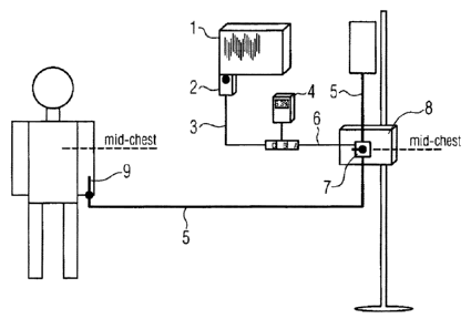
In Fig. 1 a possible configuration of a monitoring system in
a first configuration is disclosed. The monitoring system
includes as a first monitoring device a bedside monitor (BSM)
1 for receiving, storing and/or visualizing patient-related
data of a patient P. In the illustrated example, the bedside
monitor 1 is directly coupled with an arterial pressure
module 2 which receives a sensor signal from a disposable
pressure transducer (DPT) 7 as a sensor via a cable
CA 02679190 2009-08-26
WO 2008/104307 PCT/EP2008/001289
10/33
connection. The arterial pressure module 2 receives the
sensor signals and provides a communication of pressure
information obtained with the sensor signal to the bedside
monitor 1.
An arterial catheter 9 is placed inside the patient P and is
coupled with a reservoir 11 via a respective tubing 5. The
tubing 5 is configured to supply an infusion liquid from the
reservoir 11 to the patient's body. The tubing 5 is lead
through an organizer plate 8 which is preferably located at
mid-chest level of the patient. A stop cock 17 for
disconnecting the reservoir 11 from the catheter 9 is placed
on the organizer plate 8. In proximity to the stop cock 17 at
the mid-chest level a pressure transducer 7 as a sensor
device is placed at the tubing 5 to detect the pressure of
the infusion liquid within the tubing 5. The infusion liquid
in the tubing 5 transmits the blood pressure in the patient's
arterial vessels to the pressure transducer 7 at the
organizer plate 8.
The cable connection between the bedside monitor 1 and the
pressure transducer 7 includes a connection cable 3 which is
connected or connectable to the bedside monitor 1 and which
is provided with a third connector C, further referenced as
BSM plug C. The pressure transducer 7 is provided with a
pressure transducer cable 6 and provided with a first
connector A further referred to as transducer plug A.
Transducer plug A and BSM plug C can be coupled to provide
electrical connections between the bedside monitor 1 and the
pressure transducer 7.
In Fig. 2 it is schematically shown the electrical
interconnections between the bedside monitor 1 and the
disposable pressure transducer 7 as well as a structure of an
exemplary pressure transducer. In the given example, the
CA 02679190 2009-08-26
W02008/104307 PCT/EP2008/001289
11/33
disposable pressure transducer 7 has a number of four
pressure detecting elements 12 which are coupled to form a
Wheatstone bridge as it is well-known in the art, to increase
detection sensitivity. The Wheatstone bridge receives an
excitation voltage via excitation lines E+, E- which may be a
DC voltage in case of resistive detecting elements 12 and
which may be an AC voltage having a predefined oscillation
frequency and magnitude in case the detecting elements 12 are
capacitive or inductive detecting elements. From the output
nodes of the Wheatstone bridge sensor signals S+, S- are
tapped via signal lines by the bedside monitor 1. The sensor
signals S+, S- depend on the pressure to be detected
according to the states of the detecting elements 12 as well
as on the excitation voltage. Instead of pressure transducer
any kind of sensors which provide a detectable sensor signal
can be applied with each embodiment of the present invention.
In cases of a situation wherein in patient monitoring
multiple measurement devices are needed to e.g. detect the
blood pressure of the patient P the monitoring system
proposes a way to further use the pressure transducer 7 as
the sensor device for a portable measurement device 4 which
is to be further connected with the pressure transducer 7.
Fig. 3 shows schematically a second configuration of the
monitoring system wherein the portable measuring device 4 is
connected with the pressure transducer 7.
The portable measurement device 4 is provided via a
measurement cable with an intermediate connector B further
referred to as intermediate plug B. The measurement cable
includes as described above excitation lines and signal lines
to supply the pressure transducer 7 and to receive the sensor
signal from the pressure transducer 7, respectively. The
intermediate plug B is adapted to couple the portable
CA 02679190 2009-08-26
WO 2008/104307 PCT/EP2008/001289
12/33
measurement device 4 with the cable connection between the
bedside monitor 1 and the pressure transducer 7. The
intermediate plug B is coupled in between the BSM plug C and
the transducer plug A.
Fig. 4 schematically shows the electrical coupling of the
pressure transducer 7 with both the bedside monitor 1 and the
portable measurement device 4. To avoid the case that both
the bedside monitor 1 and the portable measurement device 4
provides an excitation voltage for the pressure transducer 7
preferably at least the portable measurement device 4 can
include a excitation sensing circuit 16 which detects via the
excitation lines whether an excitation voltage is already
supplied to the pressure transducer 7 and if an excitation
voltage is already supplied to the pressure transducer 7 no
excitation voltage is supplied by the portable measurement
device 4. Otherwise the portable measurement device 4
supplies an excitation voltage to the pressure transducer 7
via excitation lines.
In general, each of the monitoring devices 1, 4 connected to
the pressure transducer 7 may be configured to deliver an
excitation voltage to the pressure transducer 7 if it is not
present. In this configuration all monitoring devices to be
coupled to the detector device could be built up equally and
the monitoring device which provides the excitation to the
detector device is defined on the fly.
As mentioned above, the pressure transducer 7 has to function
with both configurations either connected to a bedside
monitor 1 only or connected simultaneously to the bedside
monitor 1 and the portable measuring device 4 in parallel.
The connection of the pressure transducer 7 to the bedside
monitor 1 may be mandatory. Then, the pressure transducer 7
CA 02679190 2009-08-26
WO 2008/104307 PCT/EP2008/001289
13/33
gets its excitation voltage from the bedside monitor 1. The
portable measurement device 4 detects the excitation voltage
and measures the sensor signal. However, the pressure reading
on the bedside monitor I may under no circumstances be
influenced by a parallel connection of the portable
measurement device 4. As the portable measurement device 4
includes an input resistance the sensor signal is influenced
by the input resistance of the sensing ports of the portable
measurement device 4 if the portable measurement device 4 is
lo connected to the cable connection. By providing the pressure
transducer 7 with a Wheatstone bridge the sensitivity with
regard to input resistances of portable measurement device 4
and/or the bedside monitor I are already substantially
decreased. Furthermore, according to the present embodiment
the connectors, i.e. the transducer plug A, the BSM plug C
and the intermediate plug B of the portable measurement
device 4 are provided with a structure which allows the
bedside monitor 1 to detect the sensor signal from the
pressure transducer 7 under the same conditions either with
the portable measurement device 4 connected or not.
In Fig. 5 the terminals of the transducer plug A are
schematically shown. The terminals for the provision of the
excitation voltages to the pressure transducer 7 are referred
to as first and second excitation terminals 20 and 21,
respectively, the signal terminals for reading the sensor
signals from the pressure transducer 7 are indicated as first
and second signal terminals 22 and 23, respectively. The
transducer plug A includes a first trimming resistance R1 and
a second trimming resistance R2. The first trimming resistant
is coupled between the first excitation terminal 20 and a
third excitation voltage terminal 24. The second trimming
resistance R2 is coupled between the first signal terminal 22
and a third signal terminal 25. The third excitation terminal
CA 02679190 2009-08-26
WO 2008/104307 PCT/EP2008/001289
14/33
24 and the third signal terminal 25 are open that means they
are not contacted in a non-contacting condition of the
transducer plug A. Furthermore, the second excitation
terminal 21 and the third excitation terminal 24 as well as
the second signal terminal 23 and the third signal terminal
25 are fully isolated from each other.
The first and the second trimming resistances R1, R2
(impedances) have respective values that simulate the
resistances (impedances) of the portable measurement device 4
if connected to the BSM plug A. Therefore, the value of the
first trimming resistance R1 is selected to correspond to the
internal resistance between the excitation terminal contacts
of the portable measurement device 4. The value of the second
trimming resistance R2 is selected to correspond to the
internal input resistance of detection signal contacts of the
portable measurement device 4 for receiving the sensor
signal.
In Fig. 6 the internal structure of the intermediate plug B
is shown. The intermediate plug B provides interconnection
wiring 33 for each of the excitation voltages E+, E- and each
of the sensor signals S+, S- which are further branched to
the portable measurement device 4 such that the portable
measurement device 4 can provide an excitation voltage,
receive an excitation voltage and may tap the sensor signal
from the pressure transducer 7 via the transducer plug A. For
coupling with the transducer plug A, the intermediate plug B
has first contacts 34 of a first outlet 31. For coupling with
the BSM plug C, the intermediate plug B has second contacts
of a second outlet 32. The first outlet 31 is structurally
30 adapted to be only connectable to the transducer plug A
wherein the second outlet 32 of the intermediate plug B is
structurally adapted to be only connectable with the BSM plug
CA 02679190 2009-08-26
WO 2008/104307 PCT/EP2008/001289
15/33
C. Thereby, faulty interconnections between the devices can
be avoided.
Fig. 7 illustrates the structure of the BSM plug C. The
respective excitation lines E+, E- and sensor signal lines
S+, S- connected with the bedside monitor 1 are coupled to
respective contacts 41.
The BSM plug C can be connected with the second outlet 32 of
the intermediate plug B such that the interconnection wiring
33 are in contact with the respective excitation lines E+, E-
l() and the signal lines S+, S- of the BSM cable. The contacts 41
of the BSM plug C can be provided as long contact pads which
are able to simultaneously contact, in a plugged condition
with plug A, the second and third excitation terminal 21, 24
as well as the second and third signal terminals 23 and 25,
respectively.
As shown in Fig. 8, the BSM plug C, the intermediate plug B
and the transducer plug A are connected with each other. An
electrical interconnection of the excitation lines and signal
lines between the transducer plug A and the BSM plug C is
provided by the interconnection wiring 33 in the intermediate
plug B. Furthermore the intermediate plug B provides the
electrical connection of the interconnection wiring 33 with
the portable measurement device 4 such that the portable
measurement device 4 receives the excitation voltage as well
as the sensor signals provided by the pressure transducer 7.
When coupling the first outlet 31 of the intermediate plug B
to the transducer plug A the first contacts 34 of the
intermediate plug B do only connect the first and second
excitation terminals 20, 21 and the first and second signal
terminals 22, 23 of the transducer plug A, respectively. The
third excitation terminal 24 and the third signal terminal 25
are not electrically contacted. One reason therefore is that
CA 02679190 2009-08-26
WO 2008/104307 PCT/EP2008/001289
16/33
between the first and second excitation terminals 20 and 21
of the transducer plug A a value of the first trimming
resistance R1 is provided as the input resistance of the
portable measurement device 4. Therefore the first trimming
resistance R1 should not be electrically effective within the
transducer plug A. The same is for the second trimming
resistor R2 which also is electrically ineffective as the
portable measurement device 4 is in electrical connection
with the first and second signal terminals 22 and 23. To
summarize, the trimming resistors (impedances) R1, R2
provided within the transducer plug A are made electrically
ineffective as they are not necessary to simulate the
internal resistances of the portable measurement device 4 as
it is already connected.
However, as shown in the configuration of Fig. 9 the BSM plug
C is configured to be also connected with the transducer plug
A. In such a configuration contacts of the BSM plug C
contacts the second excitation voltage terminal 21 and the
second signal terminal 23 in the manner described with regard
to the connection with the intermediate plug B. However, the
BSM plug C further provides an interconnection (shortcut)
between the second excitation terminal 21 and the third
excitation voltage terminal 24 as well as between the second
signal terminal 23 and the third signal terminal 25. The
shortcut make the first and second trimming resistors R1 and
R2 electrically effective such that between the first and
second excitation terminals 20, 21 as well as it been the
first and second signal terminals 22 and 23 the trimming
resistances (impedances) R1, R2 are applied which simulate
the state of a connection of the portable measurement device
4 although it is not connected to the monitoring system in
this configuration. As there is no portable measurement
CA 02679190 2009-08-26
WO 2008/104307 PCT/EP2008/001289
17/33
device 4 connected the trimming resistors R1, R2 are
electrically effective.
The plugs A, B, C can be provided with terminals and contacts
configured as simple contact pads, pins and the like which
can be contacted with corresponding terminals and contacts
which may be adapted like flexible contact beams, spring-like
contacts and the like.
In general, features for connectors A, B, and C should fulfil
following requirements:
- the transducer connector can be connected either with a
first outlet of the intermediate connector B or with an
monitoring device connector each for connecting the detector
device with a respective monitoring device;
- a second outlet of the intermediate connector is only
connectable with a monitoring device connector but not with
the transducer connector;
- in case the transducer connector is directly connected with
a monitoring device connector, trimming resistances are made
electrically effective and coupled with at least one of
excitation terminals and signal terminals of the transducer
connector;
- in case the intermediate connector is connected with the
transducer connector the trimming resistances R1, R2 are not
made electrically effective.
The embodiments of the present invention provide at least one
or more of the following advantages:
- an arterial blood pressure waveform can be measured by two
or more monitoring devices in parallel using only one sensor
CA 02679190 2009-08-26
WO 2008/104307 PCT/EP2008/001289
18/33
- known disadvantages of curve-damping by using two sensors
which would result in a larger dead space within one pressure
sensor are ruled out;
- the pressure of exactly the same heart level can be
recorded by two monitoring devices;
- the pressure transducer can be trimmed to correct impedance
conditions independently from whether it is connected to the
bedside monitor alone or to both the bedside monitor and the
portable measurement device in parallel;
- the pressure transducer is only provided with one
transducer plug which only has one outlet so safety
requirements during defibrillation are fulfilled. In other
words no open connection exists.
The principle of the present invention can be used for any
passive analogue sensor like e.g. a thermostat for
temperature measurement, a conductivity sensor or an
electrical impedance sensor as long the additional
measurement device has an adapted interface and its inner
resistance (impedance) is known as constant.
Further to the embodiment of the monitoring system of Figs. 1
and 3 the pressure transducer 7 can also be applied close to
the catheter 9. Moreover, further connectors can be provided
within the connection cables of all monitoring devices and
the sensor device.
In the above-mentioned embodiment preferably both the bedside
monitor 1 and the portable measurement device 4 are provided
with a source for an excitation voltage. Both devices may be
provided with excitation sensing circuits to decouple the
excitation voltage if an excitation voltage is already
present on the excitation lines in the cable connection
CA 02679190 2009-08-26
WO 2008/104307 PCT/EP2008/001289
19/33
between the respective measurement device and the pressure
transducer 7. However, as portable measurement devices
usually are battery powered it is preferred that the portable
measurement device is the device which decouples the
excitation voltage from the transducer in case the bedside
monitor 1 may provide the excitation voltage. In other words,
it can be provided that the provision of the excitation
voltage by the bedside monitor 1 has priority to the
provision of the excitation voltage by the portable
measurement device 4.
Another embodiment is shown in Fig. 10, wherein another
structure of a disposable sensor device in a monitoring
system is depicted. The monitoring system 50 of Fig. 10
includes a disposable sensor device 51 having a transducer 52
and a connector 55 having a first connector port to
accommodate two first signal terminals 54 and two first
supply terminals 53 as known from the embodiments described
above. Preferably, the transducer 52 and the connector 55 may
be integrally formed, however, they can also be connected
together via a suitable cable. The circuitry of the
transducer 52 (e.g. Wheatstone Bridge) may be similar or the
same as of the above embodiments. Instead of a Wheatstone
bridge a simple voltage divider comprising a series
connection of two pressure sensors or of one pressure sensor
and one or more resistors. A tap between the pressure sensors
or between the pressure sensor and the resistors provides a
single sensor signal based on the detected pressure.
The connector 55 is further provided with a second connector
port accommodating second signal terminals 56 and, as an
optional feature, second supply terminals 57, wherein each of
the first supply terminals 53 is electrically interconnected
with a respective second supply terminal 57 (if existing) and
CA 02679190 2009-08-26
WO 2008/104307 PCT/EP2008/001289
20/33
each of the first signal terminals 54 is electrically
interconnected with a respective second signal terminal 56.
To the first connector port a first plug 63 may be connected
to electrically connect a first monitoring device 60 to the
disposable sensor device 51 via the first supply lines 61 and
the first signal lines 62. Normally, the first monitoring
device 60 provides an excitation voltage via the first supply
lines to the disposable sensor device 51. The excitation
voltage can be set as already explained with respect to the
above embodiments.
The first monitoring device 60 receives a sensor signal via
the first signal lines 62 from the disposable sensor device
51 to detect the quantity to be measured, such as the blood
pressure of the patient, as already described above.
To the second connector port a second plug 73 may be
connected to connect a second monitoring device 70 to the
disposable sensor device 51 via the second supply lines 71
and the second signal lines 72. The second monitoring device
70 preferably merely receives a sensor signal via the second
signal lines 62 from the disposable sensor device 51 to
detect the quantity to be measured, but without supplying any
supply to the disposable pressure device. In that case no
supply lines need to be provided between the second plug 73
and the second monitoring device 70. Thereby, the second
monitoring device 70 can be provided without a supply source
for driving the sensor device 51 and the design effort for
the second monitoring device 70 can be reduced.
According to another embodiment, the second monitoring device
70 may be provided with an excitation sensing circuit 74
which can be connected via second supply lines with the
second supply terminals in the connector 55 of the disposable
CA 02679190 2009-08-26
WO 2008/104307 PCT/EP2008/001289
21/33
sensor device 51. The excitation sensing circuit 74 is
adapted to detect whether or not an excitation is provided
from the first monitoring device 60 via the first supply
terminals 53 and supplies an excitation voltage by its own in
case no excitation voltage can be detected via the second
supply lines 71.
In case the transducer merely includes a voltage divider or
another circuit instead of a Wheatstone bridge only one or
more than two first and second signal lines 62, 72 as well as
the respective connectors may be provided.
CA 02679190 2009-08-26
WO 2008/104307
PCT/EP2008/001289
22/33
Reference numerals
1 Bedside monitor
2 arterial pressure module
3 Cable
4 portable measurement device
Tubing
6 pressure transducer cable
7 pressure transducer
8 organizer plate
9 catheter
11 reservoir
12 pressure detecting elements
16 Excitation sensing circuit
17 Stop cock
20 First excitation terminals
21 Second excitation terminals
22 First detection signal
23 Second detection signal
24 Third excitation terminals
25 Third detection signal
31 First outlet
32 Second outlet
33 Interconnection wiring
34 First contacts
35 Second contacts
41 Contacts
51 Disposable sensor device
52 Sensor
53 First supply terminal
54 First signal terminal
55 Connector
56 Second signal terminal
CA 02679190 2009-08-26
WO 2008/104307
PCT/EP2008/001289
23/33
57 Second supply terminal
60 First monitoring device
61 First supply lines
62 First signal lines
63 First plug
70 Second monitoring device
71 First supply lines
72 First signal lines
73 Second plug
74 Excitation detection circuit