Note: Descriptions are shown in the official language in which they were submitted.
CA 02679216 2009-08-25
WO 2008/113194
PCT/CH2008/000106
- 1 -
ELECTROCONDCJCTIVE MODULAR BELT
FIELD OF THE INVENTION
[0 0 01] The present invention pertains to modular conveying
belts of the type used for conveying goods or people.
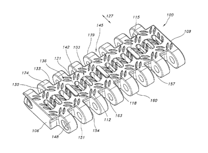
BACKGROUND OF THE INVENTION
[0002] Electroconductive belts are widely used for the
transport of goods that should not be exposed to the
discharge of static electricity. Such products may include
electronic devices and other kinds of goods that may be
damaged due to exposure to static electricity. Another
application where static electricity is undesirable is people
mover belts. With the use of conductive materials, static
electricity can be discharged through the belt to the metal
frame of the machine.
[0003] Industrial standards such as EN 61340 define the
requirements for conductive materials and applications, as
they relate to the discharge of static electricity. The
required level of conductivity may vary for different
industrial applications. A typical electrical resistance for
materials suitable for the dissipation of static electricity
is 102-105 Q(Ohm). Unfortunately, belts produced from
electroconductive materials such as electroconductive
polyacetal or electroconductive polypropylene are very
expensive. Costs of such materials may range from two to
three times the cost of standard plastic materials. The
CA 02679216 2014-07-10
20152-1312
- 2 -
plastic compounds usually contain stainless steel fibers,
carbon black fibers, or powders to make them conductive.
[0004] In order to reduce the cost, it is common to
assemble modular belts in a bricklayed module pattern by
combining standard plastic modules with electroconductive
modules. The distance between the electroconductive modules
must be small enough to always guarantee contact inside the
surface size of a standard shoe. For belt modules having a
small pitch, it is not difficult to position the modules to
meet this requirement. Various patterns for mixing the
electroconductive modules with standard plastic modules are
possible. Referring to Fig. 1, an example of a prior art
bricklayed belt 10 for a people mover application includes
standard modules 13 and electroconductive modules 16. The
footprints 19 of the user contact at least one
electroconductive module 16 to dissipate the static
electricity. This type of belt is lower in cost than a belt
constructed of all electroconductive modules, but the belt
. may still be expensive for some applications. For larger
module sizes (e.g., belts having pitches equal or larger than
two inches / 5.08 cm), mixed module patterns as described
above need a more dense arrangement of the electroconductive
modules, which increases the cost of the belt. Accordingly,
there is a need for a solution that guarantees sufficient
electroconductivity at a lower cost.
CA 02679216 2014-07-10
20152-1312
2a
SUMMARY OF THE INVENTION
[0005] According to the present invention, there is provided
belt module (100) comprising: an intermediate section (103) having a
top surface (121) and a bottom surface (170); a first plurality of
link ends (124) extending in a direction of belt travel, the first
plurality of link ends (124) having first transverse openings (142)
defined therein; a second plurality of link ends (148) extending in
a direction opposite to the first plurality of link ends (124), the
second plurality of link ends (148) having second transverse
openings (163), the second link ends (148) being offset from the
first link ends (124) such that adjacently positioned belt modules
(100) are capable of intercalating so that the first link ends (124)
of one belt module (100) fit into spaces (145) defined between the
second plurality of link ends (148) of an adjacent belt module (100)
and so that the first (142) and second (163) transverse openings are
disposed in alignment; wherein the module (100) has at least one
cavity (171) defined therein; and, an electroconductive insert (118)
disposed in the cavity (171) and extending from the top surface
(121) to the bottom surface (170) of the module (100).
[0005a] According to another aspect of the present invention,
there is provided modular belt (180) comprising: a first plurality
of belt modules (100) having an intermediate section (103) with a
top surface (121) and a bottom surface (170), the first plurality of
belt modules (100) having a first plurality of link ends (124)
extending in a direction of belt travel, the first plurality of link
ends (124) having first transverse openings (142) defined therein; a
second plurality of link ends (148) extending in a direction
opposite to the first plurality of link ends (124), the second
plurality of link ends (148) having second transverse openings
(163); wherein the module (100) has at least one cavity (171)
defined therein; an electroconductive insert (118) disposed in the
cavity (171) and extending from the top surface (121) to the bottom
surface (170) of the module (100); a second plurality of belt
CA 02679216 2014-07-10
20152-1312
2b
modules (100) having an intermediate section (103); the second
plurality of belt modules (100) having a first plurality of link
ends (124) extending in a direction of belt travel, the first
plurality of link ends (124) having first transverse openings (142)
defined therein; a second plurality of link ends (148) extending in
a direction opposite to the first plurality of link ends (124), the
second plurality of link ends (148) having second transverse
openings (163); wherein the first link ends (124) on the first
plurality of belt modules (100) are capable of intercalating with
the second link ends (148) on the second plurality of belt modules
(100) to form a belt (180) capable of articulating about a sprocket;
and, at least one pivot rod (101) capable of being installed in
aligned transverse openings (142, 163) of the first and second belt
modules (100).
[0005b] According to a further aspect of the present invention,
there is provided method of forming a modular belt (180) capable of
dissipating static electricity, the method comprising: providing a
first plurality of belt modules (100) having an intermediate section
(103) with a top surface (121) and a bottom surface (170), the first
plurality of belt modules (100) having a first plurality of link
ends (124) extending in a direction of belt travel, the first
plurality of link ends (124) having first transverse openings (142)
defined therein; a second plurality of link ends (148) extending in
a direction opposite the first plurality of link ends (124), the
second plurality of link ends (148) having second transverse
openings (163); wherein the module (100) has at least one cavity
(171) defined therein; an electroconductive insert (118) disposed in
the cavity (171) and extending from the top surface (121) to the
bottom surface (170) of the module (100); providing a second
plurality of belt modules (100) having an intermediate section
(103); the second plurality of belt modules (100) having a first
plurality of link ends (124) extending in a direction of belt
travel, the first plurality of link ends (124) having first
transverse openings (142) defined therein; a second plurality of
CA 02679216 2014-07-10
20152-1312
2c
link ends (148) extending in a direction opposite to the first
plurality of link ends (124), the second plurality of link ends
(148) having second transverse openings (163); wherein the first
link ends (124) on the first plurality of belt modules (100) are
capable of intercalating with the second link ends (148) on the
second plurality of belt modules (100) to form a belt (180) capable
of articulating about a sprocket; and, installing at least one pivot
rod (101) in the aligned transverse openings (142, 163) of the first
and second belt modules (100).
CA 02679216 2014-07-10
20152-1312
- 3 -
[0006] The essence of the invention consists in the
following:
[0007] A modular belt has plug-inserts produced from
electroconductive material. The plugs may be snapped into
respective holes that are preformed or machined in a standard
plastic belt module. The modules may be produced from low
cost materials such as polypropylene or polyacetal. The
electroconductive plugs may be attached to the belt in
numerous ways including, but not limited to, snap fit,
gluing, screwing or direct integration by molding.
BRIEF DESCRIPTION OF THE DRAWING FIGURES
[0008] The invention is illustrated in the drawings in
which like reference characters designate the same or similar
= parts throughout the figures of which:
Fig. 1 is a plan view of a prior art belt for a people
= mover application with mixed modules;
Fig. 2 is a top perspective view of an embodiment of a
belt module according to the present invention;
Fig. 3 is a bottom perspective view of the belt module
= of Fig. 2;
Fig. 4 is a cross sectional view of the module of Fig. 2
with an electroconductive plug-insert installed therein; and,
CA 02679216 2009-08-25
WO 2008/113194
PCT/CH2008/000106
- 4 -
Fig . 5 is a top plan view of an embodiment of a modular
belt according to the present invention used in a people
mover application.
DETAILED DESCRIPTION OF THE INVENTION
[0009] Referring to Figs. 2-5 generally and initially to
Fig. 2, a belt module 100 has an intermediate section 103
extending from a first side edge 106 to a second side
edge 109. The intermediate section 103 may be provided with
slots 112 defined therein. The slots 112 may function to
remove water or debris from the assembled belt. The
intermediate section 103 also includes openings 115 for
receiving plugs 118. The plugs 118 are constructed from
electroconductive materials. A typical electrical resistance
for materials suitable for the dissipation of static
electricity is 102-105 Q (Ohm). Generally, the resistance
values for conductors is in the range of about zero to 105
(Ohm), for dissipators is about 105-1012 Q (Ohm) and for
insulators is greater than about 1012 Q (Ohm). The plugs 118
extend for a short distance above the top surface 121 of the
belt module 100 such that contact with an item (not shown)
supported on the top surface 121 of the belt is possible. The
plugs 118 also extend below the bottom surface of the
module 100 as described below. The plug 118 may be
constructed of a unitary member or it could be a composite
structure with more than one part in electrical
communication. The plugs 118 may be fixed in the openings 115
by numerous methods and devices including, but not limited
to, snap fit, gluing, screwing, or direct integration of the
plugs 118 by molding.
CA 02679216 2009-08-25
WO 2008/113194
PCT/CH2008/000106
- 5 -
[0010] A first plurality of link ends 124 extend in a
direction of belt travel indicated by arrow 127. The first
plurality of link ends 124 have a first side wall 130 and a
second side wall 133. The first and second side walls 130,
133 define a transverse thickness. The link end 124 has a
proximal end 136 where it joins with the intermediate
section 103 and has a distal end 139 disposed opposite
therefrom. A transverse pivot rod opening 142 extends from
the first side wall 130 to the second side wall 133. The
first plurality of link ends 124 have spaces 145 disposed
therebetween.
[0011] A second plurality of link ends 148 extend in the
opposite direction from the first plurality of link ends 124.
The second plurality of link ends 148 are offset from the
first plurality of link ends 124 such that when adjacent
modules 100 are juxtaposed the second plurality of link
ends 148 fit into the spaces 145. The second plurality of
link ends 148 have a first sidewall 151 and a second
sidewall 154 defining a transverse thickness. The link
end 148 has a proximal end 157 that intersects with
intermediate section 103 and has a distal end 160 disposed
opposite therefrom. The second link end 148 also includes a
transverse opening 163 that extends from the first
sidewall 151 to the second sidewall 154.
[0012] The module 100 is designed such that like
modules 100 can be arranged with the first plurality of link
ends 124 on a first module 100 intercalated with the second
plurality of link ends 148 on an adjacent module 100. With
the adjacent modules 100 intercalated, a transverse pivot
rod 101 can be inserted to connect the modules 100 to form a
belt 180 (Fig. 5). The belt 180 may be formed in many
CA 02679216 2009-08-25
WO 2008/113194
PCT/CH2008/000106
- 6 -
different ways as will be evident to those of ordinary skill
in the art based on this disclosure. The belt 180 may be
formed of rows of modules with one module per row. As an
alternative, the belt 180 may be formed with multiple
modules 100 per row in a "bricklayed" configuration as will
be evident to those of ordinary skill in the art based on
this disclosure.
[0013] In Fig. 3, the bottom surface 170 of belt
module 100 is shown. The bottom surface 170 borders a
cavity 171 formed with walls 172, 174, 176 and 178. The
cavity 171 may receive the tooth of a sprocket (not shown)
for driving the module 100 as will be evident to those of
ordinary skill in the art based on this disclosure.
[0014] The electroconductive plugs 118 extend over the
full height of the module 100 and should extend slightly
below the bottom surface 170 of the module 100 in order to
guarantee contact with a support base of the belt 180. The
support base is usually constructed from a conductive
material such that the static electricity may be discharged
over the metal frame of the machine. Another possibility is
to use discharge brushes on the bottom of the plugs 118 as
will be evident to those of ordinary skill in the art based
on this disclosure.
[0015] The present invention eliminates the need for
molding entire modules from materials having
electroconductive properties. In one example of the
invention, the plugs 118 can be snapped into respective
openings 115. The openings 115 may be pre-formed or machined
into the belt modules 100. The module 100 may be produced
from standard low cost plastic resins such as polypropylene
CA 02679216 2009-08-25
WO 2008/113194
PCT/CH2008/000106
- 7 -
or polyacetal that may have low conductivity or even be
classified as insulators.
[0016] Turning to Fig. 4, one embodiment of the plug 118
is shown. The plug 118 slides into the opening 115 which may
be provided with a rib 200 that engages with a recess 203 in
the side of the plug 118 to provide a friction fit. As shown,
the plug 118 extends from above the top surface 121 of the
module to a position below the bottom surface 170 of the
module 100. The plug 118 is shown with a pair of cavities 206
and 209 formed therein. The plug 118 may be made from
numerous materials, have different degrees of flexibility and
may or may not be provided with cavities. Also, depending on
the method used to fix the plugs 118 to the module 100 there
may or may not be a rib 200 and recess 203. Other methods of
attachment are also possible as set forth above.
[0017] In Fig. 5, a belt 180 is shown with a plurality of
rows 350, 353, 356, 359, 362, 365, 368, 371 extending from a
first side edge 374 to a second side edge 377 of the
belt 180. Each row is comprised of multiple modules 100 and
standard modules 400 arranged in bricklayed fashion such that
the modules in adjacent rows are staggered so that the seams
in each row are out of alignment. As shown, the plugs 118 are
spaced such that for a people mover application, the average
footprint 380 applied to any portion of the belt 180 will
contact at least one plug 118 to dissipate the static
electricity.
[0018] The number and distribution of the plugs 118
determines the minimum size of an object that will be
contacted by at least one plug 118 when supported from any
position on the top surface of the belt 180. The level of
CA 02679216 2009-08-25
WO 2008/113194
PCT/CH2008/000106
- 8 -
electroconductivity is determined by the nature of the
conductive material used for the plug 118.
[0019] The present invention provides many advantages
including the reduction of costs by using plugs 118 instead
of modules constructed entirely from electroconductive
materials. Also, the present invention provides a flexible
solution because a specific belt type can be furnished with
any number of electroconductive plugs 118. Because the
plugs 118 are separate items that are attached to the
belt 180, it is easy to produce them with any material
particularly suitable for a specific application. This
interchangeability allows the user to optimize the
electroconductivity performance adapted to the specific
application and requirements.
[0020] While the invention has been described in
connection with certain embodiments, it is not intended to
limit the scope of the invention to the particular forms set
forth, but, on the contrary, it is intended to cover such
alternatives, modifications, and equivalents as may be
included within the scope of the invention as defined by the
appended claims.